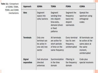
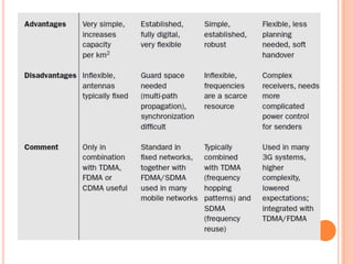
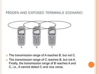
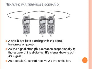
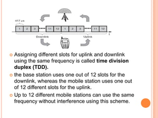
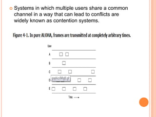
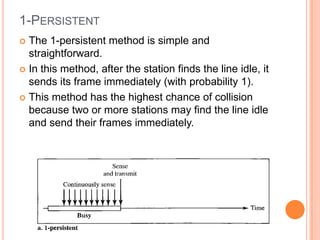
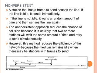
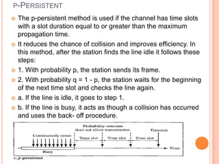
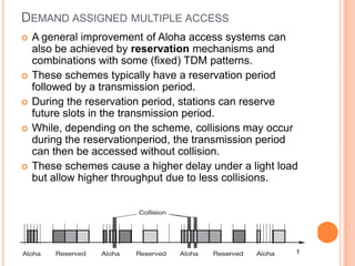
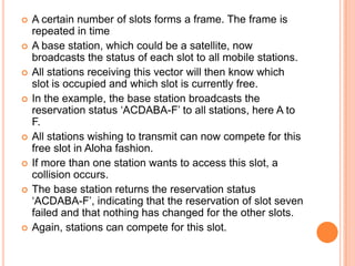
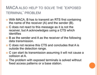
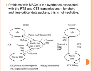
The document discusses media access control (MAC) protocols for wireless networks. It explains that standard MAC schemes from wired networks often fail in wireless scenarios due to signal attenuation over distance and the hidden terminal problem. It provides examples of the hidden terminal, exposed terminal, and near-far terminal problems that can occur in wireless networks. It then summarizes several MAC protocols used in wireless networks, including CSMA/CA, TDMA, FDMA, and ALOHA/Slotted ALOHA.

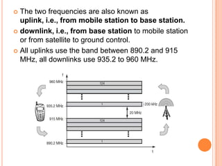
![ CDMA is based on coding theory. Each station is
assigned a code, which is a sequence of numbers called
chips.
They are called orthogonal sequences and have the
following properties:
1. Each sequence is made of N elements, where N is
the number of stations.
2. If we multiply a sequence by a number, every element
in the sequence is multiplied by that element. This is
called multiplication of a sequence by a scalar.
For example, 2. [+1 +1-1-1]=[+2+2-2-2]
3. If we multiply two equal sequences, element by
element, and add the results, we get N, where N is the
number of elements in the each sequence.](https://image.slidesharecdn.com/wierlessnetworksch31-130309152654-phpapp01/85/Wierless-networks-ch3-1-46-320.jpg)
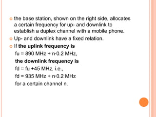
![ This is called the inner product of two equal
sequences. For example,
[+1 +1-1 -1]· [+1 +1 -1 -1] = 1 + 1 + 1 + 1 = 4
4. If we multiply two different sequences, element by
element, and add the results, we get O. This is called
inner product of two different sequences.
For example,
[+1 +1 -1 -1] • [+1 +1 +1 +1] = 1 + 1 - 1 - 1 = 0
5. Adding two sequences means adding the
corresponding elements. The result is another
sequence.
For example,
[+1+1-1-1]+[+1+1+1+1]=[+2+2 00]](https://image.slidesharecdn.com/wierlessnetworksch31-130309152654-phpapp01/85/Wierless-networks-ch3-1-47-320.jpg)
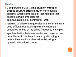
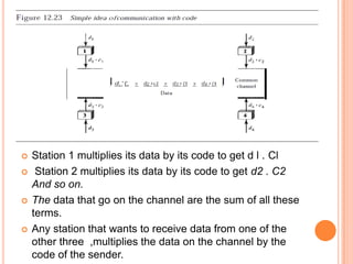
![ The sequence on the channel is the sum of all four
sequences as defined before
Now imagine station 3, which we said is silent, is
listening to station 2.
Station 3 multiplies the total data on the channel by
the code for station 2, which is [+1 -1 +1-1], to get](https://image.slidesharecdn.com/wierlessnetworksch31-130309152654-phpapp01/85/Wierless-networks-ch3-1-49-320.jpg)