Downloaded 194 times
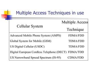


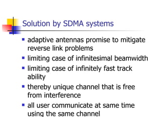
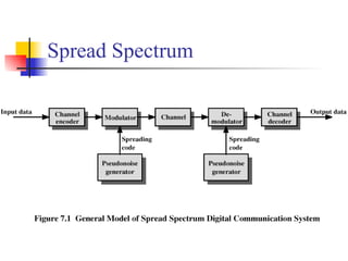
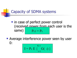
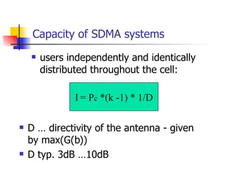
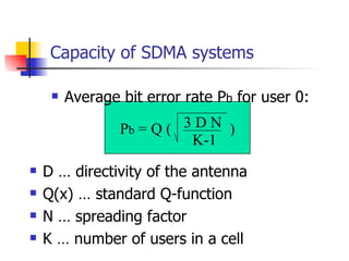
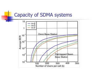

The document discusses multiple access techniques for wireless communications, focusing on methods such as FDMA, TDMA, CDMA, and SDMA, explaining their operational principles and equipment requirements. It highlights the trade-offs, efficiencies, and practical applications of each technique, including their impacts on user capacity and signal quality. Additionally, it examines the complexities of signal management, power control, and interference in mobile communication systems.


![B.I.T , MESRA [M.Tech] Assignment : MULTIPLE ACCESS TECHNIQUES FOR WIRELESS ...](https://cdn.slidesharecdn.com/ss_thumbnails/multipleaccesstechniquesassignmentfinal-170820115158-thumbnail.jpg?width=640&height=640&fit=bounds)


