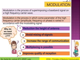
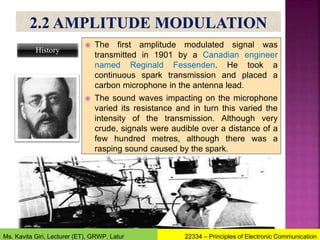
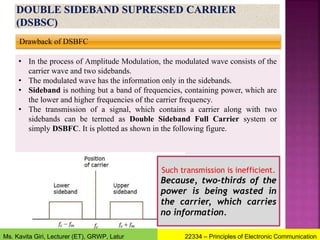
The document focuses on the principles of electronic communication, specifically modulation techniques including amplitude (AM), frequency (FM), and phase modulation (PM). It discusses the necessity for modulation in improving communication distance, avoiding signal mixing, enabling multiplexing, and enhancing reception quality. Additionally, it covers mathematical representations, modulation index, bandwidth requirements, advantages, and disadvantages of AM signals.

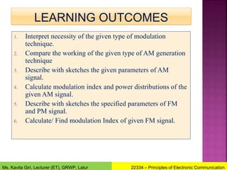


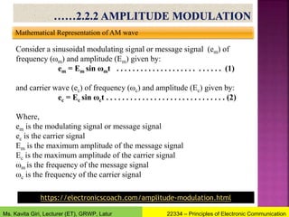
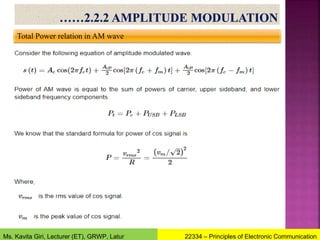
![Mathematical Representation of AM wave
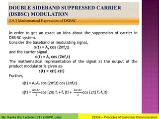
The AM wave is expressed by the following expression,
eAM = A sin (2πfct) …………………………………………. (3)
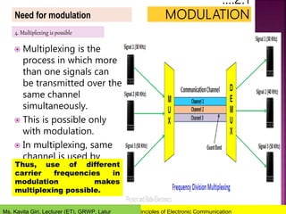
Where, A represents the instantaneous value of the envelope.
The modulating signal either adds or gets subtracted from the
peak carrier amplitude Ec.
Hence we can represent the instantaneous value of envelope
as, A = Ec + em
= Ec + Em sin ωmt ………………………………………….(4)
Hence the AM wave is given by,
eAM = A sin (2πfct)
eAM = [Ec + Em sin (2πfm t)] sin (2πfct)
eAM = Ec [1 + (Em/Ec)sin (2πfm t)] sin(2πfct)
Let m= Em/Ec be the modulation index.
eAM= Ec [1 + m sin (2πfm t)] sin (2πfct)……………(5)
22334 – Principles of Electronic Communication
Ms. Kavita Giri, Lecturer (ET), GRWP, Latur](https://image.slidesharecdn.com/chapter2amandfm-220301093342/85/Amplitude-Modulation-and-Frequency-Modulation-21-320.jpg)
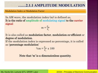
![Frequency Spectrum of AM wave
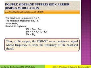
Consider the equation for AM wave,
eAM = [Ec + Em cos (ωm t)] cos (ωct)
eAM = Ec [1 + (Em/Ec)cos (ωm t)] cos (ωct)
As per the definition of modulation index, m= Em/Ec
eAM= Ec [1 + mcos (ωm t)] cos (ωct)……………(5)
Simplifying we get,
eAM= Ec cos (ωct) + m Ec cos (ωm t). cos (ωct)………………(6)
For the second term we can use the following identity:
2 cos A cos B = cos (A+B) + cos (A-B)
Therefore, equation (6) gets simplified as follows:
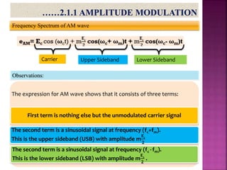
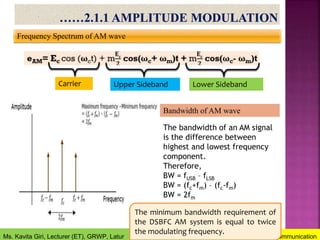
eAM= Ec cos (ωct) + m
𝐄𝐜
𝟐
cos(ωc+ ωm)t + m
𝐄𝐜
𝟐
cos(ωc- ωm)t
Carrier Upper Sideband Lower Sideband
22334 – Principles of Electronic Communication
Ms. Kavita Giri, Lecturer (ET), GRWP, Latur](https://image.slidesharecdn.com/chapter2amandfm-220301093342/85/Amplitude-Modulation-and-Frequency-Modulation-27-320.jpg)
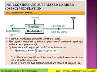
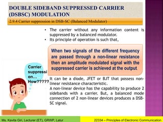
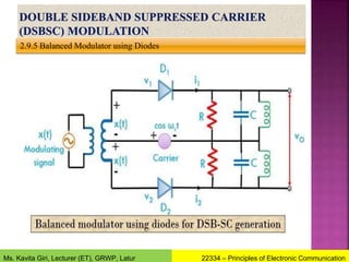
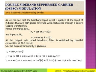
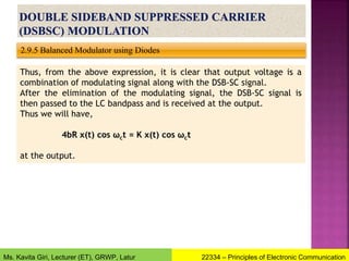
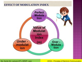
![2.9.5 Balanced Modulator using Diodes
Similarly,
the output voltage is given by
vo = i1 R – i2 R
On substituting the above-given value of i1 and i2 in the output
equation, we will have,
vo = R [2 a x(t)] (+ 4b x (t) cos ωct)]
Therefore, the output is,
vo = 2aR x(t) + 4bRx (t) cos ωct
modulating signal DSB-SC signal
22334 – Principles of Electronic Communication
Ms. Kavita Giri, Lecturer (ET), GRWP, Latur](https://image.slidesharecdn.com/chapter2amandfm-220301093342/85/Amplitude-Modulation-and-Frequency-Modulation-48-320.jpg)