Ch 9 shaper, planner, slotter
•Download as PPTX, PDF•
15 likes•11,151 views

The document discusses various aspects of shapers, planers, and slotters. It describes: 1) Shapers and planers use a single-point cutting tool in a straight-line motion to generate flat surfaces on workpieces, with intermittent feed between strokes on shapers. 2) Shapers use a quick return mechanism to rapidly return the cutting tool, with cutting speed varying over the stroke. 3) Slotters are essentially vertical shapers used to machine keyways and other non-flat surfaces. 4) Hydraulic shapers provide more constant cutting speed over the stroke compared to mechanical shapers.

Recommended
More Related Content
What's hot
What's hot (20)
Similar to Ch 9 shaper, planner, slotter
Similar to Ch 9 shaper, planner, slotter (20)
More from Nandan Choudhary
More from Nandan Choudhary (20)
Recently uploaded
Recently uploaded (20)
Ch 9 shaper, planner, slotter
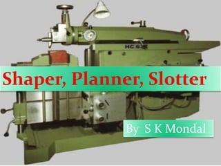
- 1. Shaper, Planner, Slotter By S K Mondal
- 3. Shaper The relative motions between the tool and the workpiece, shaping and planing use a straight-line cutting motion with a single-point cutting tool to generate a flat surface. In shaping, the workpiece is fed at right angles to the cutting motion between successive strokes of the tool. For either shaping or planing, the tool is held in a clapper box which prevents the cutting edge from being damaged on the return stroke of the tool. Relatively skilled workers are required to operate shapers and planers, and most of the shapes that can be produced on them also can be made by much more productive processes, such as milling, broaching, or grinding.
- 4. Shaper
- 5. Quick return motion Mechanism
- 6. Quick return motion Mechanism In shaping, the cutting tool is held in the tool post located in the ram, which reciprocates over the work with a forward stroke, cutting at velocity V and a quick return stroke at velocity VR. The rpm rate of the drive crank (Ns) drives the ram and determines the velocity of the operation. The stroke ratio, 0 360 s cutting stroke angle R
- 7. Ram Drive The mechanical ram drive is a slotted arm quick return motion mechanism,
- 8. Feed Mechanism Table feed is intermittent and is accomplished on the return (non cutting) stroke when the tool has cleared the workpiece. The cross feed is given to the table with the help of a cross feed screw which is actuated by a pawl which engages a notched wheel (ratchet) keyed to the screw.
- 9. Classification of Shaper Machine Shapers, as machine tools usually are classified according to their general design features as follows, 1. Horizontal a. Push-cut b. Pull-cut or draw cut shaper 2. Vertical a. Regular or slotters b. Keyseaters 3. Special purpose
- 10. Formula Cutting speed, Number of strokes, Time of one stroke, Total time, (1 ) 1000 NL m V s w N f (1 ) min 1000 L m t V (1 ) (1 ) min 1000 1000 s L m Lw m T N v vf
- 11. Hydraulic Shaper
- 12. Advantages of hydraulic shaping 1. Cutting speed remains constant throughout most of the cutting stroke, unlike the crank shaper where the speed changes continuously. 2. Since the power available remains constant throughout, it is possible to utilise the full capacity of the cutting tool during the cutting stroke. 3. The ram reverses quickly without any shock due the hydraulic cylinder utilised. The inertia of the moving parts is relatively small. 4. The range and number of cutting strokes possible are relatively large in hydraulic shaper. 5. More strokes per minute can be achieved by consuming less time for reversal and return strokes.
- 13. Planer Planing can be used to produce horizontal, vertical, or inclined flat surfaces on workpieces that are too large to be accommodated on shapers. Planing is much less efficient than other basic machining processes, such as milling, that will produce such surfaces. Planing and planers have largely been replaced by planer milling machines or machines that can do both milling and planing.
- 14. Slotter Slotting machine is basically a vertical axis shaper. Thus the workpieces, which cannot be conveniently held in shaper, can be machined in a slotter. Generally, keyways, splines, serrations, rectangular grooves and similar shapes are machined in a slotting machine. The stroke of the ram is smaller in slotting machines than in shapers to account for the type of the work that is handled in them.
- 16. Slotter
- 17. Slotter The types of tools used in a slotter are very similar to those in a shaper, except that the cutting actually takes place in the direction of cutting. However, in view of the type of surfaces that are possible in the case of slotter, a large variety of boring bars or single-point tools with long shanks are used.
- 18. IAS - 1994 Stroke of a shaping machine is 250 mm. It makes 30 double strokes per minute. Overall average speed of operation is (a) 3.75 m/min (b) 5.0 m/min (c) 7.5 m/min (d) 15 m/min
- 19. GATE-2012 (PI) In a shaping process, the number of double strokes per minute is 30 and the quick return ratio is 0.6. If the length of the stroke is 250 mm, the average cutting velocity in m/min is (a) 3.0 (b) 4.5 (c) 7.5 (d) 12.0
- 20. GATE - 2005 A 600 mm x 30 mm flat surface of a plate is to be finish machined on a shaper. The plate has been fixed with the 600 mm side along the tool travel direction. If the tool over-travel at each end of the plate is 20 mm, average cutting speed is 8 m/min, feed rate is 0.3 mm/stroke and the ratio of return time to cutting time of the tool is 1:2, the time required for machining will be (a) 8 minutes (b) 12 minutes (c) 16 minutes (d) 20 minutes
- 21. IES – 1994, ISRO-2008 Given that, average cutting speed = 9 m/min, the return time to cutting time ratio is = 1 : 2, the feed rate = 0.3 mm/stroke, the clearance at each end of cut = 25 mm and that the plate is fixed with 700 mm side along the direction of tool travel, the time required for finishing one flat surface of a plate of size 700 x 30 mm in a shaper, will be (a) 10 min (b) 12.5 min (c) 15 min (d) 20 min
- 22. GATE-2014 A cast iron block of 200 mm length is being shaped in a shaping machine with a depth of cut of 4 mm, feed of 0.25 mm/stroke and the tool principal cutting edge angle of 30o. Number of cutting strokes per minute is 60. Using specific energy for cutting as 1.49 J/mm3 the average power consumption (in watt) is ………….
- 23. IES - 2004 Consider the following alignment tests on machine tools 1. Straightness 2. Flatness 3. Run out 4. Parallelism Which of the above alignment tests on machine tools are common to both lathe and shaper? (a) 1 and 2 (b) 2 and 3 (c) 3 and 4 (d) 1 and 4
- 24. IES - 2001 In a shaper machine, the mechanism for tool feed is (a) Geneva mechanism (b) Whitworth mechanism (c) Ratchet and Pawl mechanism (d) Ward- Leonard system
- 25. IES 2010 Assertion (A): Longitudinal cutting motion of the tool and cross-wise feed motion of the job generates flat surfaces in planning process. Reason (R): Jobs used in planning machines are generally long and heavy compared to shaping. (a) Both A and R are individually true and R is the correct explanation of A (b) Both A and R are individually true but R is NOT the correct explanation of A (c) A is true but R is false (d) A is false but R is true
- 26. IES - 1997 Which of the following are the advantages of a hydraulic shaper over a mechanically driven shaper? 1. More strokes per minute can be obtained at a given cutting speed. 2. The cutting stroke has a definite stopping point. 3. It is simpler in construction. 4. Cutting speed is constant throughout most of the cutting stroke. Select the correct answer using the codes given below: (a) 1 and 2 (b) 1 and 4 (c) 2 and 4 (d) 1, 3 and 4
- 27. IES - 1995 In a mechanical shaper, the length of stroke is increased by (a) Increasing the centre distance of bull gear and crank pin (b) Decreasing the centre distance of bull gear and crank pin (c) Increasing the length of the ram (d) Decreasing the length of the slot in the slotted lever
- 28. IAS - 1995 Size of a shaper is given by (a) Stroke length (b) Motor power (c) Weight of the machine (d) Table size.
- 29. ISRO-2010 The cutting speed of the tool in a mechanical shaper is (a) Maximum at the beginning of the cutting stroke (b) Maximum at the end of the cutting stroke (c) Maximum at the middle of the cutting stroke (d) Minimum at the middle of the cutting stroke
- 30. GATE-2014 (PI) Match the following (a) P1-Q2-R4-S3 (b) P2-Q1-R4-S3 (c) P4-Q1-R2-S3 (d) P2-Q3-R1-S4 Group I (Mechanism) Group II (Machines) P Quick return 1 Lathe Q Apron 2 Shaping R Intermittent indexing 3 Gear hobbing S Differential mechanism 4 Milling
Editor's Notes
- The process of shaping and planing are among the oldest single-point machining processes. They have largely been replaced by milling and broaching, as production processes.
- The motor drives the bull gear, which carries a pin, in a circular motion. The rpm of the bull gear is controlled by the motor. This pin fits into the slot of the rocker and is free to slide in a straight line path. As the bull gear rotates, the rocker arm oscillates about its pivot point, The end of the rocker arm is connected to the ram of the shaper through a link arm. The length of the stroke is changed by changing the radius of the circle in which the pin on the bull gear rotates. The length of travel should be a little longer than the actual length of the workpiece. This allows sufficient the for the tool block of the clapper box to swing back to its position for cutting.
- The mechanical shaper has the problem of iertia of the main drive components, which require some time for reversal for every stroke and as a result, a large proportion of time is spent with the tool cutting air. An alternative drive system can be provided by means of a simple hydraulic circuit to provide the reciprocating Motion.
- Ans. (d) Average speed of operation m/min.
- Ans. (d)
- Ans. (b)
- Ans. 295 to 305
- Ans. (d)
- Ans. (c)
- Ans. (d)
- Ans. (b) Advantages of hydraulic shaping are as follows. 1. Cutting speed remains constant throughout most of the cutting stroke, unlike the crank shaper where the speed changes continuously. 2. Since the power available remains constant throughout, it is possible to utilise the full capacity of the cutting tool during the cutting stroke. 3. The ram reverses quickly without any shock due the hydraulic cylinder utilised. The inertia of the moving parts is relatively small. 4. The range and number of cutting speeds possible are relatively large in hydraulic shaper. 5. More strokes per minute can be achieved by consuming less time for reversal and return strokes.
- Ans. (a)
- Ans. (a)
- Ans. (c)
- Ans. (b)