Downloaded 258 times
![IES-2015 Conventional
Explain the principle of Electro Chemical machining
process with the help of a diagram.
[10 Marks]](https://image.slidesharecdn.com/ch-12unconventionalmachining-170423125731/85/Ch-12-unconventional-machining-30-320.jpg)
![IAS-2011 Main
What is the principle of electro-chemical
machining (ECM)?
What are the advantages and disadvantages of
ECM over conventional drilling?
Comment on the surface finish and the accuracy of
the ECM.
[20-Marks]](https://image.slidesharecdn.com/ch-12unconventionalmachining-170423125731/85/Ch-12-unconventional-machining-37-320.jpg)


![IES 2011 Conventional
Discuss the effects of insufficient dielectric and
electrolyte circulation in the inter-electrode gap on the
Electric Discharge machining and Electro Chemical
Machining process respectively. [5 Marks]](https://image.slidesharecdn.com/ch-12unconventionalmachining-170423125731/85/Ch-12-unconventional-machining-87-320.jpg)
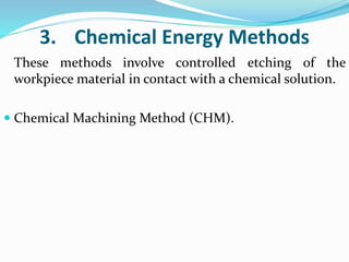
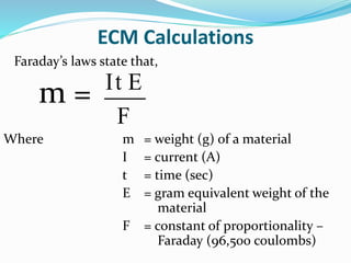
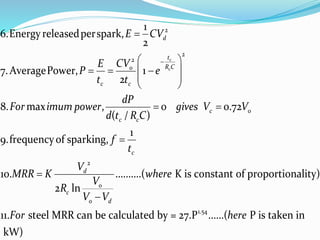
![Formulae
o
1. Thevoltageacrossthegapatany time , (1 )
[WhereV =Voltageof powersupply,
R Resistanceof charging circuit
C= Capacitanceof charging circuit]
2.Timeconstant,
3.Charging time(Timerequiredtogapvoltag
c
t
R C
o
c
c
t V V e
R C
etoreach V )
ln
4.Dischargevoltage, (1 )
5.Charging current,
c
c
c
d
o
c c
o d
t
R C
d o
t
R Co
c
c
V
t R C
V V
V V e
V
i e
R
](https://image.slidesharecdn.com/ch-12unconventionalmachining-170423125731/85/Ch-12-unconventional-machining-89-320.jpg)
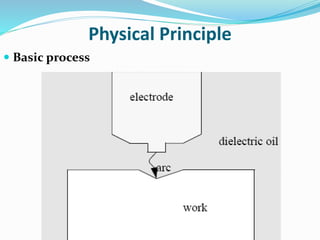
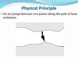
![IES 2009 Conventional
i. What is the principle of metal removal in EDM
process?
ii. Describe the process with the help of sketch.
iii. List advantages and limitations of the system.
[ 15 marks]](https://image.slidesharecdn.com/ch-12unconventionalmachining-170423125731/85/Ch-12-unconventional-machining-99-320.jpg)

![IFS-2011
Write the advantages, limitations and applications of
electron beam machining. What is the safety problem
connected with EBM?
[5-Marks]](https://image.slidesharecdn.com/ch-12unconventionalmachining-170423125731/85/Ch-12-unconventional-machining-156-320.jpg)
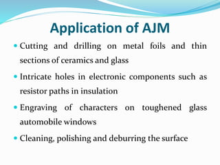
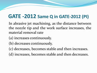
![IAS-2011 Main
State the mechanism of cutting by abrasive jet.
What are the advantages and disadvantages of
AJM ? Mention two applications.
[10-Marks]](https://image.slidesharecdn.com/ch-12unconventionalmachining-170423125731/85/Ch-12-unconventional-machining-171-320.jpg)
![IFS-2011
What are the disadvantages of abrasive jet machining?
Write some of its applications.
[5-Marks]](https://image.slidesharecdn.com/ch-12unconventionalmachining-170423125731/85/Ch-12-unconventional-machining-172-320.jpg)
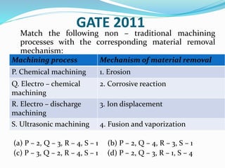

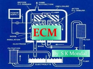
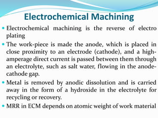
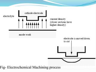
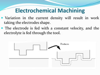
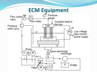
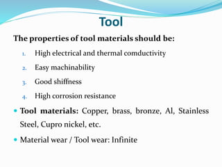
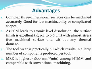
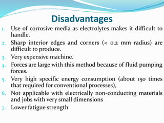
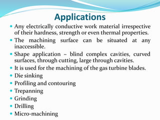
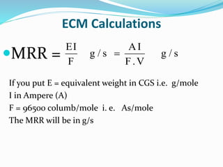
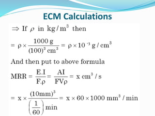
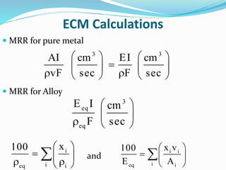
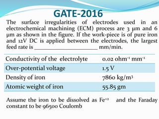
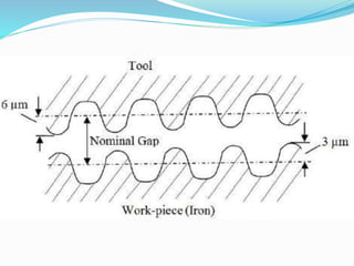
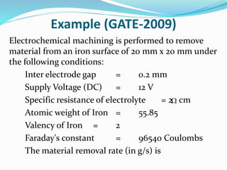
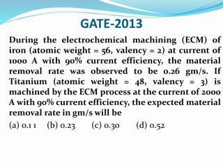
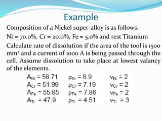
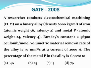
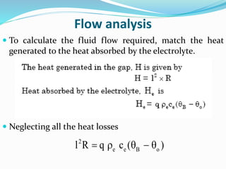
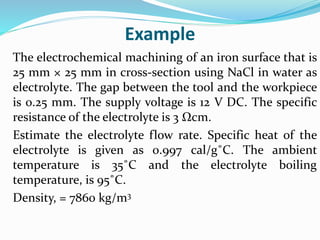
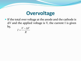
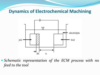
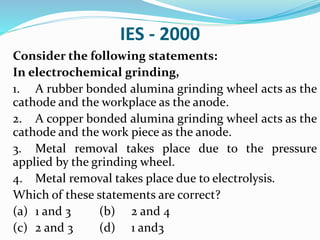
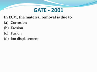
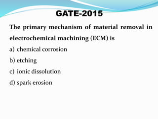
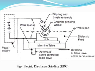
The document discusses electrochemical machining (ECM). ECM is an unconventional machining process where material is removed from a workpiece made of an electrically conductive material via an electrochemical reaction. In ECM, the workpiece acts as an anode in an electrolyte solution, and a tool acts as a cathode. A direct current is passed between them, causing metal ions from the workpiece to dissolve into the electrolyte solution. ECM can machine complex shapes with high accuracy and no tool wear. It has the highest material removal rate of any unconventional machining process but requires expensive equipment and a conductive workpiece material.


