Downloaded 10 times
![R. Giridharan, Pankaj Kumar, P. Vijayakumar and R. Tamilselvan
http://www.iaeme.com/IJMET/index.asp 115 editor@iaeme.com
• I = number of treatments
• N
t = total number of cases
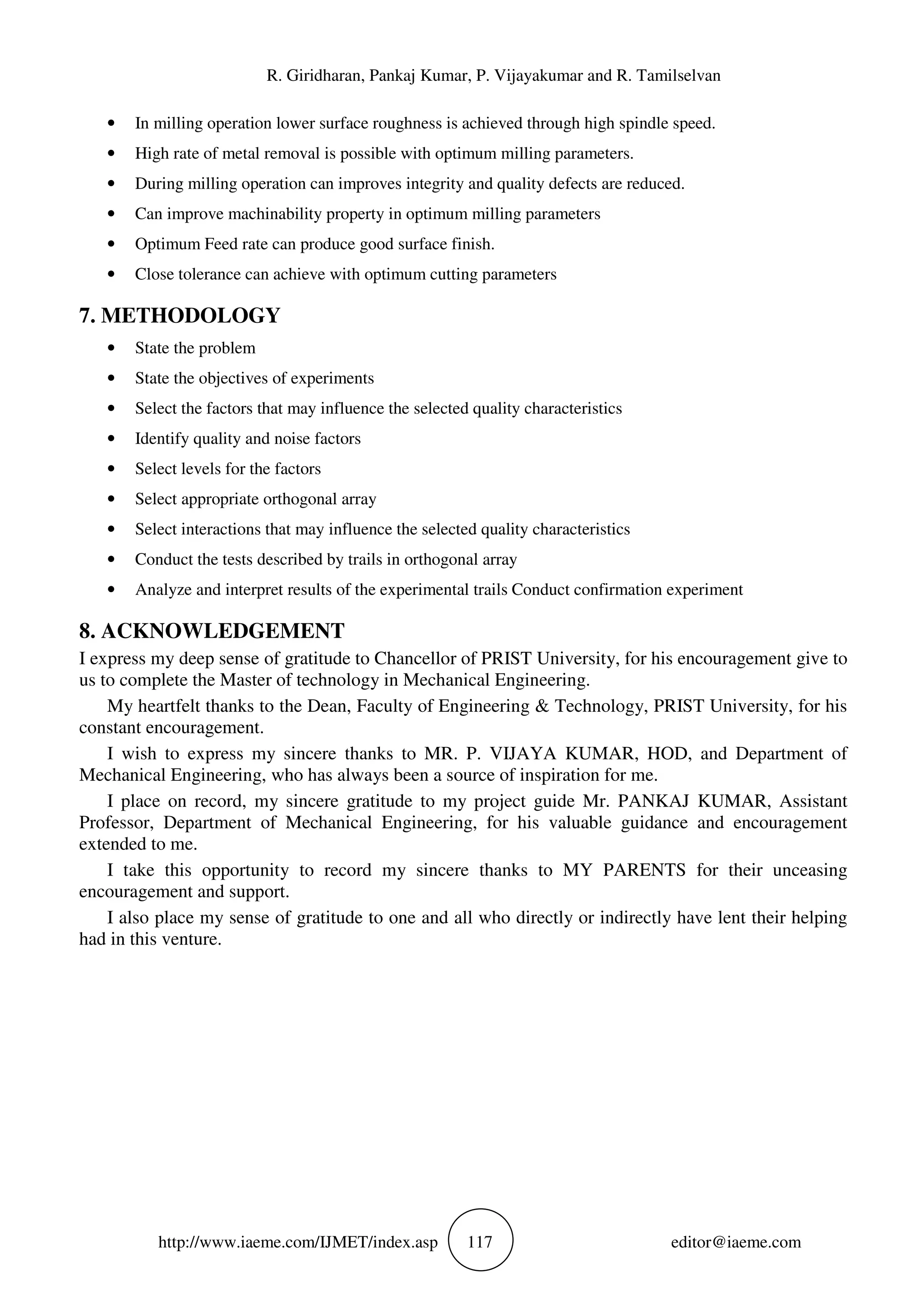
3. UNITS
• mm/s = millimeter/Second
• rpm =Revolution per meter
• mm = millimeter
• mm/rev = millimeter/revolution
• mm3
/s = millimeter Cubic/Second
4. EQUATIONS
L9 = [(l-1) x p] +1
= [(3-1) x 3] +1 = 7 ≈ l9
Vc = Dcap x π x n
1000
fz = vf
n x Zc
SSTotal = SSError + SSTreatments
F= Variance between treatments
Variance within treatments
F= MSTreatments = SSTreatments/ (I-1)
MSError SSError/ (nT-I)
5. THE MILLING PROCESS PARAMETERS
Although there are many different types of milling cutter, understanding chip formation is
fundamental to the use of any of them. As the milling cutter rotates, the material to be cut is fed into it,
and each tooth of the cutter cuts away a small chip of material. Achieving the correct size of chip is of
critical importance. The size of this chip depends on several variables.
• Surface cutting speed (Vc): This is the speed at which each tooth cuts through the material as the tool
spins. This is measured either in meters per minute in metric countries, or surface feet per minute
(SFM) in America. Typical values for cutting speed are 166.666667mm/sec to 1000mm/sec for some
steels, and 100m/min and 10000mm/sec for aluminum. This should not be confused with the feed rate.
This value is also known as "tangential velocity."
• Spindle speed (S): This is the rotation speed of the tool, and is measured in revolutions per minute
(rpm). Typical values are from hundreds of rpm, up to tens of thousands of rpm.
• Feed per tooth (Fz): This is the distance the material is fed into the cutter as each tooth rotates. This
value is the size of the deepest cut the tooth will make.
• Feed rate (F): This is the speed at which the material is fed into the cutter. Typical values are from
20mm/min to 5000mm/min.](https://image.slidesharecdn.com/ijmet0802014-170314053747/75/EXPERIMENTAL-INVESTIGATION-AND-DESIGN-OPTIMIZATION-OF-END-MILLING-PROCESS-PARAMETERS-ON-MONEL-400-BY-TAGUCHI-METHOD-3-2048.jpg)
![R. Giridharan, Pankaj Kumar, P. Vijayakumar and R. Tamilselvan
http://www.iaeme.com/IJMET/index.asp 121 editor@iaeme.com
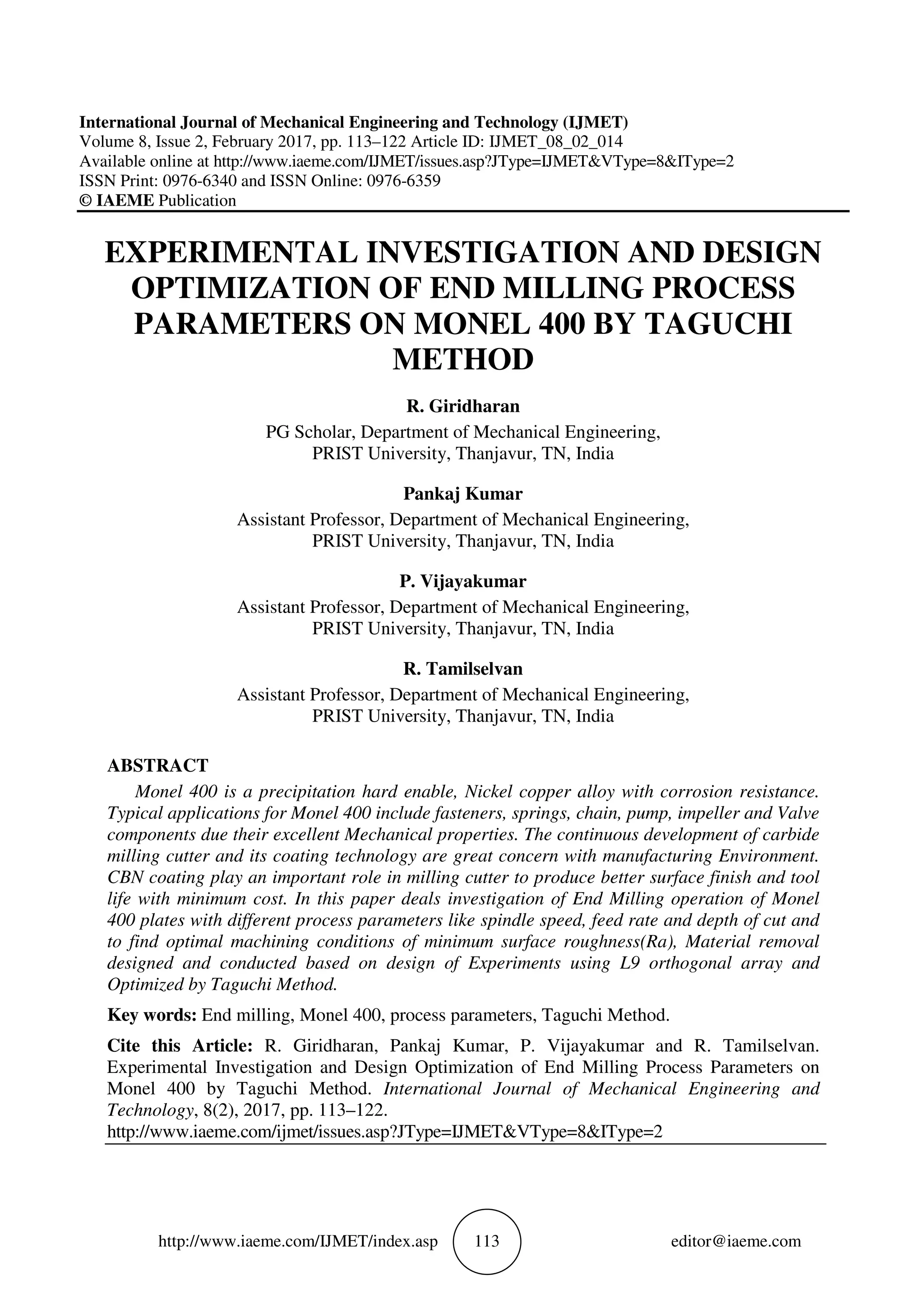
Table 8 S/N ratio for Metal removal rate
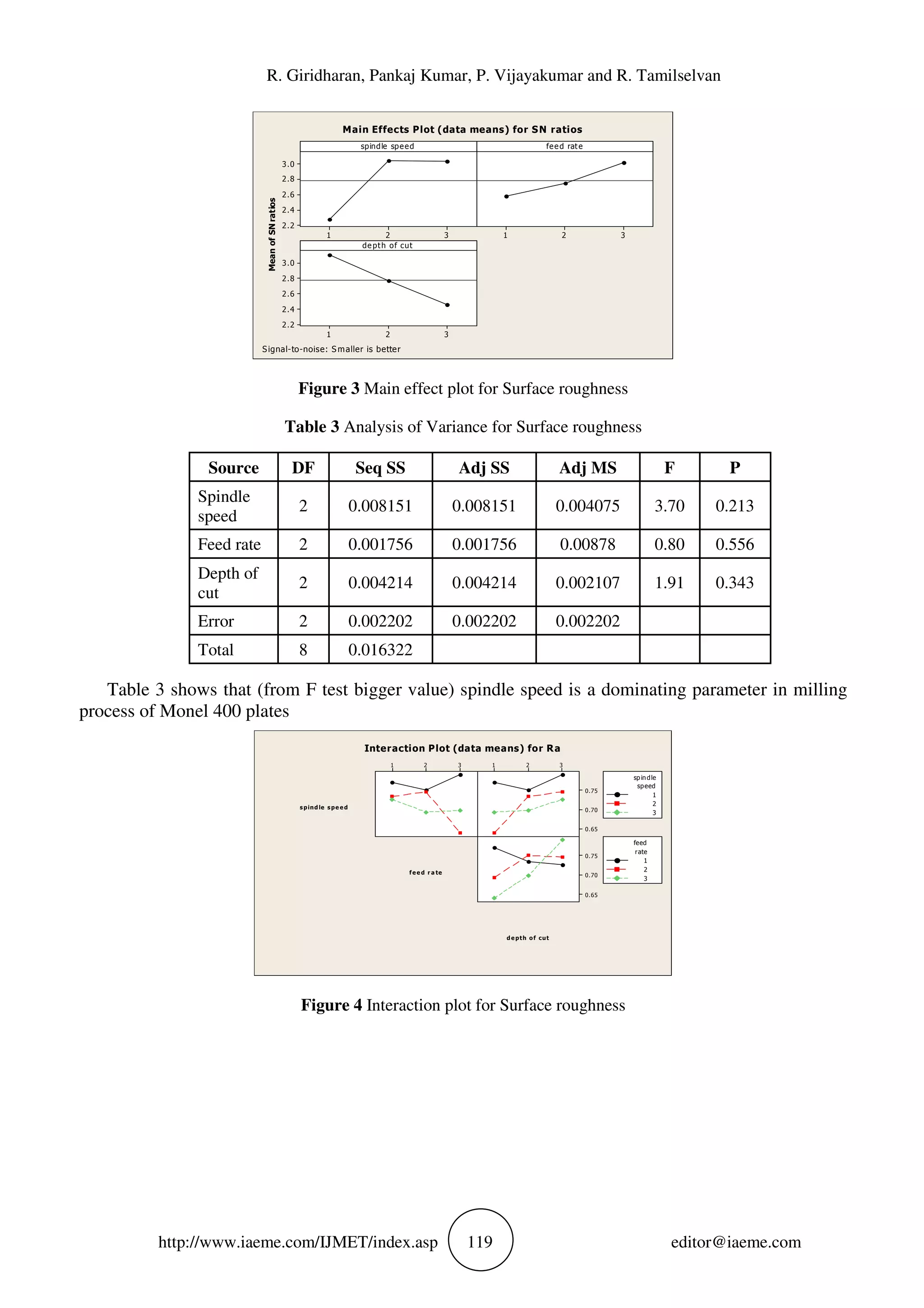
Table 8 shows that feed rate is a dominating parameter of metal removal rate of milling process on
Monel 400
depth of cut
feedrate
3.02.52.01.51.0
3.0
2.5
2.0
1.5
1.0
MRR
10 - 15
15 - 20
20 - 25
25 - 30
30 - 35
<
> 35
5
5 - 10
Contour Plot of MRR vs feed rate, depth of cut
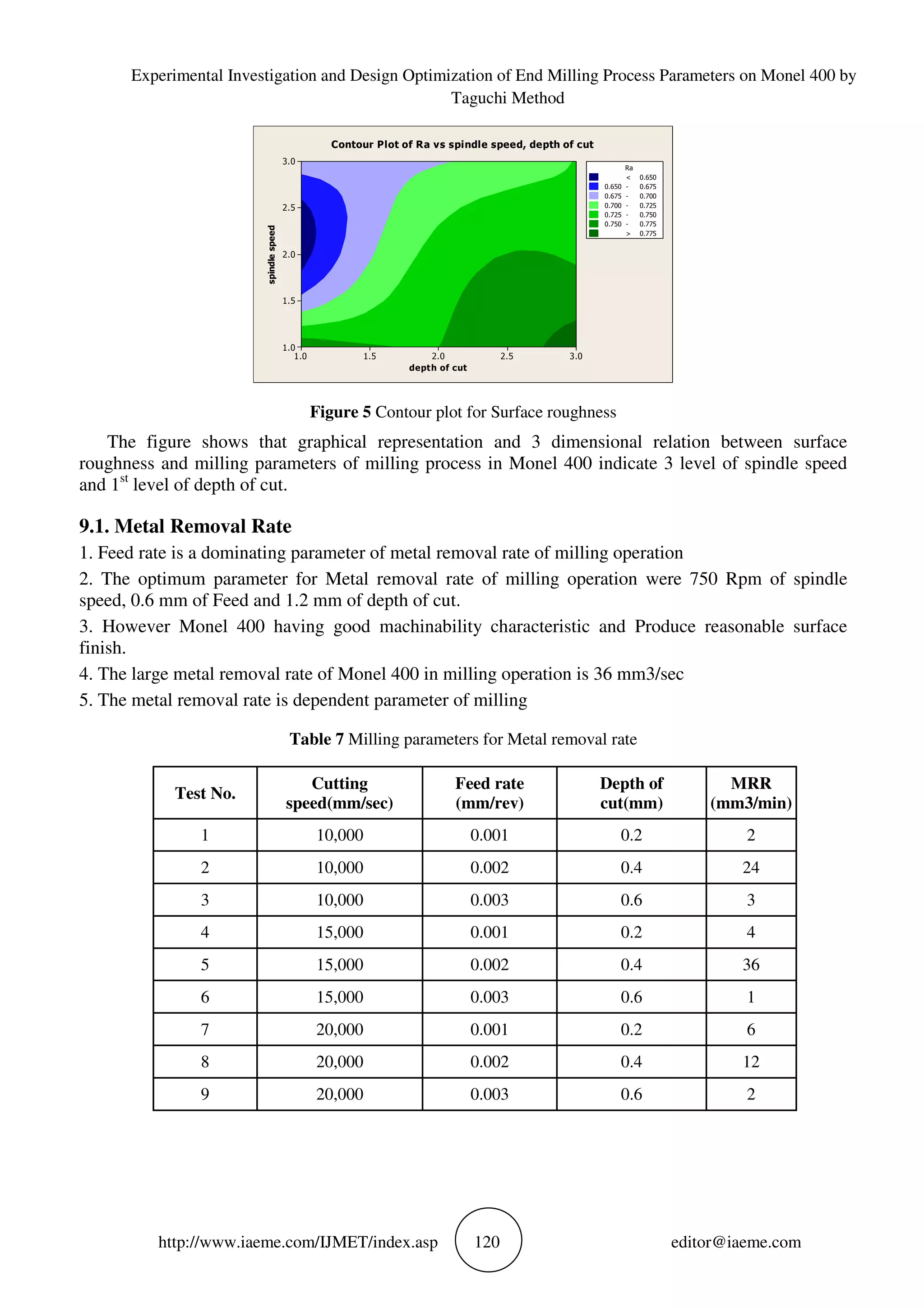
Figure 6 Contour plot for MRR
The figure shows that graphical and 3 dimensional representation of metal removal rate of milling
process in 3 rd level of depth of cut and 2 nd level of feed rate .this is optimum parameter of metal
removal rate.
10. CONCLUSION
Optimization of process is done for Monel 400 (by response surface methodology and taguchi method
to get better surface roughness).The regression provides very good fit and can be used to predict
roughness throughout the reason of Experimentation’s. The Coefficient of determination of so
obtained is high (0.965 or 0.952) which is very good.
REFERENCES
[1] G.Akhyar and C.H.Che Haron, 2008,”Application of Taguchi method in the Optimization of
Turning Parameters for surface roughness”, International journal of science engineering and
technology Vol.1, No.3. 1.
[2] Taguchi methods in the optimization of cutting parameters for surface finish and whole diameter
accuracy in dry drilling process”, international journal of advanced manufacturing technology.
International journal of Advanced manufacturing Technology, Vol.29, pp.867-878.
[3] Ching-kao Chang and Lu.H.S, 2006,”study on the prediction model of surface roughness for side
milling operations”, International journal of Advanced manufacturing Technology, Vol.29, pp.867-
878.
Level Spindle speed Feed rate Depth of cut
1 14.389 11.208 9.201
2 14.389 26,771 15.222
3 14.389 5.188 18.744
Delta 0.000 21.584 9.542
Rank 3 1 2](https://image.slidesharecdn.com/ijmet0802014-170314053747/75/EXPERIMENTAL-INVESTIGATION-AND-DESIGN-OPTIMIZATION-OF-END-MILLING-PROCESS-PARAMETERS-ON-MONEL-400-BY-TAGUCHI-METHOD-9-2048.jpg)
![Experimental Investigation and Design Optimization of End Milling Process Parameters on Monel 400 by
Taguchi Method
http://www.iaeme.com/IJMET/index.asp 122 editor@iaeme.com
[4] Alam.S, Nurul Amin.A.K.M and Patwari.A.U, 2008, “Surface roughness prediction model in high
speed end-milling of Ti-6Al-4V”, Competitive Manufacturing, Proc of the 2ndIntl & 23rd
AIMTDR conf.
[5] Pravin Kumar.S, Venkatakrishnan.R And Vignesh Babu.S, Process Failure Mode and Effect
Analysis on End Milling Process- A Critical Study, International Journal of Mechanical
Engineering and Technology, 4(5), 2013, pp. 191–199.
[6] Cemal Cakir.M, Cihat Ensarioglu and llker demirayak, 2009,”Mathematical modeling of surface
roughness for evaluating the effects of cutting parameters and coating material”, Journal of
materials processing technology, Vol.209, pp.102-109.
[7] Suresh.P.V.S, Venkateswara Rao.P and Deshmukh.S.G, 2002,”A genetic algorithm approach for
optimization of surface roughness prediction model”, International journal of machine tools and
manufacture, Vol.42, pp.675-680.
[8] Yung-Kuang Yang,Ming-Tsam Chuang and Show-Shyan Lin,2009,”Optimization of dry machining
parameters for high-purity graphite in end milling process via design of experiments methods”,
Journal of Materials Processing Technology,Vol 209,PP.4395-4400.
[9] Kareem Idan Fadheel and Dr. Mohammad Tariq, Optimization of End Milling Parameters of AISI
1055 by Taguchi Method, International Journal of Advanced Research in Engineering and
Technology (IJARET), 5(3), 2014, pp. 09–20
[10] Babur Ozcelik and Mahmut Bayramogulu, 2006,”The statistical modeling of surface roughness for
side milling operations”, International Journal of Advanced manufacturing Technology, Vol.29,
pp.867-878.
[11] Zhang JZ,Chen JC,Kirby ED (2007),Surface Roughness Optimization in an End-Milling Operation
Using the Taguchi Design Method,J.Mat.Processing Technol.,187(4):233-239.
[12] El-Sonbaty.I.A, Khashaba.U.A, Selmy.A.l and Ali.I.A, 2008,”Prediction of surface roughness
profiles for milled surfaces using an artificial neural network and fractal geometry approach”,
Journal of Materials Processing Technology, Vol.200, pp.271-278.](https://image.slidesharecdn.com/ijmet0802014-170314053747/75/EXPERIMENTAL-INVESTIGATION-AND-DESIGN-OPTIMIZATION-OF-END-MILLING-PROCESS-PARAMETERS-ON-MONEL-400-BY-TAGUCHI-METHOD-10-2048.jpg)

The document presents an experimental investigation and design optimization of end milling process parameters for Monel 400, a nickel-copper alloy, using the Taguchi method. Key focus areas include the effects of spindle speed, feed rate, and depth of cut on surface roughness and material removal rate. The study concludes that spindle speed is a dominant factor affecting surface quality and that optimal parameters lead to improved machinability and reduced wear during milling.


![[IJET V2I4P3] Authors: N.Keerthi, N.Deepthi,N.Jaya Krishna](https://cdn.slidesharecdn.com/ss_thumbnails/ijet-v2i4p3-160810100959-thumbnail.jpg?width=640&height=640&fit=bounds)