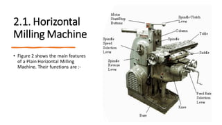
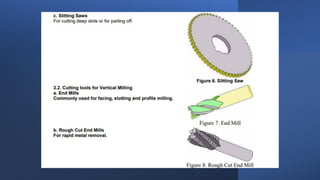
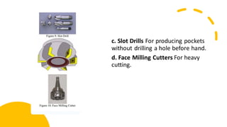
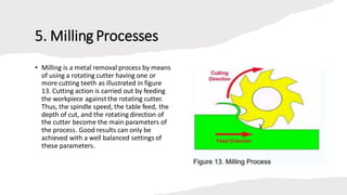
1. Milling Introduction
2. Types of Milling Machine
2.1 Horizontal Milling Machine
2.2 Vertical Milling Machine
3. Cutting Tools
3.1 Cutting Tools for HorizontalMilling Machine
3.2 Cutting Tools for Vertical Milling Machine
4. Industrial Applications
5. Milling Processes
5.1 Spindle Speed
5.2 Feed Rate
5.3 Depth of Cut
5.4 Directionof Cutter Rotation
6. Typical Milling Operations
6.1 Plain Milling
6.2 End Milling
6.3 Gang Milling
6.4 Straddle Milling
7. Milling SetUp
7.1 Vice Alignment
7.2 Work Holding Method
8. Safety
9. References
1. Milling Introduction
• Milling machine is one of the most versatile conventional machine
tools with a wide range of metal cutting capability. Many complicated
operations such as indexing, gang milling, and straddle milling etc. can
be carried out on a milling machine.
• This training module is intended to give you a good appreciation on
the type of milling machines and the various types of milling
processes. Emphasis is placed on its industrial applications,
operations, and the selection of appropriate cutting tools.
2. Types of Milling Machine
• Most of the milling machine are constructed of ¡¥column and
knee¡¦ structure and they are classified into two main types
namely Horizontal Milling Machine and Vertical Milling Machine. The
name Horizontal or Vertical is given to the machine by virtue of its
spindle axis. Horizontal machines can be further classified into
Plain Horizontal and Universal Milling Machine. The main
difference between the two is that the table of an Universal Milling
Machine can be set at an angle for helical milling while the table of a
Plain Horizontal Milling Machine is not.
2.1. Horizontal
Milling Machine
• Figure 2 shows the main features
of a Plain Horizontal Milling
Machine. Their functions are :-
a. Column The column houses the spindle, the bearings, the gear box,
the clutches, the shafts, the pumps, and the shifting mechanisms for
transmitting power from the electric motor to the spindle at a selected
speed.
b. Knee The knee mounted in front of the column is for supporting the
table and to provide an up or down motion along the Z axis.
c. Saddle The saddle consists of two slideways, one on the top and one
at the bottom located at 90º to each other, for providing motions in the
X or Y axes by means of lead screws.
d. Table The table is mounted on top of the saddle and can be moved
along the X axis. On top of the table are some T-slots for the mounting
of workpiece or clamping fixtures.
e. Arbor The arbor is an extension of the spindle for mounting cutters.
Usually, the thread end of an arbor is of left hand helix.
f. Base The base of the milling machine, along with the column, are the
major structural components. They hold, align, and support the rest of the
machine.
g. SpindleThe spindle holds the tool and provides the actual tool rotation.
h. SpindleReverse Lever The position of this lever determines the spindle
direction. The three positions of the handle are; In, Middle, and Out. The
middle position is the neutral position. Never move the spindle reverse lever
when the spindle is turning.
ı. SpindleSpeed SelectionLever The spindle speed selection lever is used to
change the spindle R.P.M. setting. This type of machine has a geared head so
the spindle speed can only be changed when the spindle is stopped.
j. Spindle Clutch Lever The spindle clutch lever engages the spindle
clutch to the motor. By manipulating the spindle clutch lever the
operator can start and stop the spindle.
k. Feed Rate Selection Lever The feed rate selection lever is used to
change the feed rate setting. The feed rate settings are expressed in
inches per minute.
l. Motor Start and Stop Buttons The motor start and stop buttons
control the power to the main motor for the machine
2.2. Vertical Milling Machine
• Figure 3 shows a vertical milling machine which is of similar
construction to a horizontal milling machine except that the spindle is
mounted in the vertical position. Its additional features are :-
a.Milling
head The milling head consisting the spindle, the motor, and the
feed control unit is mounted on a swivel base such that it can be set at
any angle to the table.
b. Ram
The ram on which the milling head is attached can be positioned
forward and backward along the slideway on the top of the column.
3. Cutting Tools
• 3.1. Cutting Tools for Horizontal
• a. Slab Mills For heavy cutting of large and flat
surfaces.
b. Side and Face Cutters This type of cutters has
cutting edges on the periphery and sides of the
teeth for cutting shoulders and slots.
c. Slot Drills For producing pockets
without drilling a hole before hand.
d. Face Milling Cutters For heavy
cutting.
4. Industrial Applications
Milling machines are widely used in the tool and die making industry
and are commonly used in the manufacturing industry for the
production of a wide range of components as shown in figure 11.
Typical examples are the milling of flat surface, indexing, gear cutting,
as well as the cutting of slots and key-ways
5. Milling Processes
• Milling is a metal removal process by means
of using a rotating cutter having one or
more cutting teeth as illustrated in figure
13. Cutting action is carried out by feeding
the workpiece againstthe rotating cutter.
Thus, the spindle speed, the table feed, the
depth of cut, and the rotating direction of
the cutter become the main parameters of
the process. Good results can only be
achieved with a well balanced settings of
these parameters.
5.1. Spindle Speed
• Spindle speed in revolution per minute
(R.P.M.)for the cutter can be calculated
from the equation :-
• where -- N = R.P.M. of the cutter
• CS = Linear Cutting Speed of the
material in m/min. ( see table 1 )
• d = Diameter of cutter in mm
• 5.2. Feed Rate Feed rate : (F) is defined as the rate of
travel of the workpiece in mm/min. But most tool
suppliers recommend it as the movement per tooth of
the cutter (f).
• Thus, F = f . u . N
• where -- F = table feed in mm/min
• f = movement per tooth of cutter in mm ( see table 1 )
• u = number of teeth of cutter
• N = R.P.M. of the cutter where C.S. and feed rate for
some common material :
5.3. Depth of Cut: Depth of cut is directly related to the
efficiency of the cutting process. The deeper the cut the faster
will be the production rate. Yet, it still depends on the strength
of the cutter and the material to be cut. For a certain type of
cutter, a typical range of cut will be recommended by the
supplier. Nevertheless, it should be noted that a finer cut is
usually associated with a better surface finish as well as a long
tool life.
5.4. Directionof Cutter Rotation: a. Up Cut Milling In up cut
milling, the cutter rotates in a direction opposite to the table
feed as illustrated in figure 14. It is conventionally used in most
milling operations because the backlash between the
leadscrew and the nut of the machine table can be eliminated.
b. Down Cut Milling
In down cut milling, the cutter rotates in
the same direction as the table feed as
illustrated in figure 15. This method is
also known as Climb Milling and can only
be used on machines equipped with a
backlash eliminator or on a CNC milling
machine. This method, when properly
treated, will require less power in
feeding the table and give a better
surface finish on the workpiece
6. Typical Milling
Operations
6.1. Plain Milling
Plain milling is the milling of
a flat surface with the axis
of the cutter parallel to the
machining surface. It can be
carried out either on a
horizontal machine or a
vertical machine as shown
in figure 16.
6.2. End Milling 12 End Milling is the milling of a flat
surface with the axis of the cutter perpendicular to
the machining surface as shown in figure 17.
6.3. Gang Milling Gang milling is a horizontal milling
operation that utilises three or more milling cutters
grouped together for the milling of a complex surface
in one pass. As illustrated in figure 18, different type
and size of cutters should be selected for achieving
the desire profile on the workpiece.
6.4. Straddle Milling In straddle milling, a group of spacers is mounted
in between two side and face milling cutters on the spindle arbor as
shown in figure 19. for the milling of two surfaces parallel to each other
at a given distance.
7. Milling machinevices
• The milling machine vise is the most common type of work holding
devise used on the milling machine (Figure 1).
• The plain milling machine vise is used for holding work which has
parallel sides. The vise is bolted directly to the table using the T-slots
in the machine table. The plain vise can be accompanied by a swivel
base (Figure 2).
• The swivel base is graduated in degrees and allows the vise
to swivel in the horizontal plane. The swivel base gives the
vise a greater degree of versatility,but should be avoided
when doing heavy rough cutting operations because it
reduces the rigidity of the setup. For machining operations
involving compound angles, a universal vise is commonly
used (Figure 4).
• The universal vise allows the operator to tilt the workpiece
90 degrees in the vertical plane as well as swivel it 360
degrees in the horizontal plane.
• In high production situations an air or hydraulically
actuated vise may be used. These types of vises are quick
acting. They also maintain consistentclamping pressures
from one part to the next. However, on most manual type
milling machines the vise is opened or closed using a
handle. When tightening a plain type milling machine vise
it is not necessary to strike the handle of the vise (Figure
5).
• Striking the vise handle with a hammer can either cause the vise to
become overtightened or cause the vise handle to break. If it
becomes apparent that the vise is not holding properly, check with
your instructor for other possible causes to the problem.
• V - Blocks V-Blocks hold and support round work for milling or drilling
(Figure 7). V-Blocks come in many different sizes. On milling
machines, V-Blocks are typically clamped directly to the table (Figure
8).
• Angel plates An angle plate is an L shaped piece of Cast Iron or Steel
that has tapped holes or slots to facilitate the clamping of the
workpiece(Figure 9).Angle plates are used when parts need to have
machining operations performed at a 90 degree angle to the axis of
the table(Figure 10 ).
• In Figure 15 please study the correct and incorrect direct clamping
practices
7.1. Vice AlignmentIn the setting up of the vice onto the machine table, the
fix jaw of the vice must be set parallel to the machine table using a Parallel
Bar and a Dial Indicator.Adjustments can only be made by using a hide face
hammer to correct its position such that a near zero indicator movement is
achieved at all positions along the parallel bar.
7.2. Work Holding Method In the machining of a complex component, it is
usually started off with the milling of a rectangular block. To ensure that
each surface of the rectangular block is perpendicular to its neighbouring
surfaces, the following points should be noted:-
• The vice jaws and the workpiece must be free from burrs, chips, and
cutting fluid.
• Smaller workpiece should be supported by parallel bars to provide
the supporting datum.
• Round bar must be placed between the workpiece and the movable
jaw to ensure that the workpiece is in perfect contactwith the fix jaw.
• The vice handle should be tightened by hand to avoid over
clamping of the workpiece as well as the vice. Hide face hammer
should be used to assure that the workpiece is in perfect contact with
the supporting base.
• On completion of the milling of the first face, the workpiece
should be unloaded, deburred, and cleaned before the next operation.
• To machine the second and the third faces, the workpiece should
be clamped with its preceding machined surface facing against the fix
jaw of the vice.
• Similar clamping method can be applied in the machining of the
fourth face.
• Yet it can also be clamped on the vice without the round bar.
• Both ends of the workpiece can be machined with the periphery
flutes of the cutter using up cut milling as shown in figure below.
8. Safety
• Safety practices of a machine shop should be followed. A complete
understanding of the Safety Rules would enable the students to
identify potential hazards that may occur under different working
conditions such that appropriate preventive actions can be taken to
avoid the happening of accidents.
MILLING PRESENTATION.pdf

MILLING PRESENTATION.pdf

  • 2.
    1. Milling Introduction 2.Types of Milling Machine 2.1 Horizontal Milling Machine 2.2 Vertical Milling Machine 3. Cutting Tools 3.1 Cutting Tools for HorizontalMilling Machine 3.2 Cutting Tools for Vertical Milling Machine 4. Industrial Applications 5. Milling Processes 5.1 Spindle Speed 5.2 Feed Rate 5.3 Depth of Cut 5.4 Directionof Cutter Rotation
  • 3.
    6. Typical MillingOperations 6.1 Plain Milling 6.2 End Milling 6.3 Gang Milling 6.4 Straddle Milling 7. Milling SetUp 7.1 Vice Alignment 7.2 Work Holding Method 8. Safety 9. References
  • 4.
    1. Milling Introduction •Milling machine is one of the most versatile conventional machine tools with a wide range of metal cutting capability. Many complicated operations such as indexing, gang milling, and straddle milling etc. can be carried out on a milling machine. • This training module is intended to give you a good appreciation on the type of milling machines and the various types of milling processes. Emphasis is placed on its industrial applications, operations, and the selection of appropriate cutting tools.
  • 5.
    2. Types ofMilling Machine • Most of the milling machine are constructed of ¡¥column and knee¡¦ structure and they are classified into two main types namely Horizontal Milling Machine and Vertical Milling Machine. The name Horizontal or Vertical is given to the machine by virtue of its spindle axis. Horizontal machines can be further classified into Plain Horizontal and Universal Milling Machine. The main difference between the two is that the table of an Universal Milling Machine can be set at an angle for helical milling while the table of a Plain Horizontal Milling Machine is not.
  • 6.
    2.1. Horizontal Milling Machine •Figure 2 shows the main features of a Plain Horizontal Milling Machine. Their functions are :-
  • 7.
    a. Column Thecolumn houses the spindle, the bearings, the gear box, the clutches, the shafts, the pumps, and the shifting mechanisms for transmitting power from the electric motor to the spindle at a selected speed. b. Knee The knee mounted in front of the column is for supporting the table and to provide an up or down motion along the Z axis. c. Saddle The saddle consists of two slideways, one on the top and one at the bottom located at 90º to each other, for providing motions in the X or Y axes by means of lead screws. d. Table The table is mounted on top of the saddle and can be moved along the X axis. On top of the table are some T-slots for the mounting of workpiece or clamping fixtures.
  • 8.
    e. Arbor Thearbor is an extension of the spindle for mounting cutters. Usually, the thread end of an arbor is of left hand helix. f. Base The base of the milling machine, along with the column, are the major structural components. They hold, align, and support the rest of the machine. g. SpindleThe spindle holds the tool and provides the actual tool rotation. h. SpindleReverse Lever The position of this lever determines the spindle direction. The three positions of the handle are; In, Middle, and Out. The middle position is the neutral position. Never move the spindle reverse lever when the spindle is turning. ı. SpindleSpeed SelectionLever The spindle speed selection lever is used to change the spindle R.P.M. setting. This type of machine has a geared head so the spindle speed can only be changed when the spindle is stopped.
  • 9.
    j. Spindle ClutchLever The spindle clutch lever engages the spindle clutch to the motor. By manipulating the spindle clutch lever the operator can start and stop the spindle. k. Feed Rate Selection Lever The feed rate selection lever is used to change the feed rate setting. The feed rate settings are expressed in inches per minute. l. Motor Start and Stop Buttons The motor start and stop buttons control the power to the main motor for the machine
  • 10.
    2.2. Vertical MillingMachine • Figure 3 shows a vertical milling machine which is of similar construction to a horizontal milling machine except that the spindle is mounted in the vertical position. Its additional features are :- a.Milling head The milling head consisting the spindle, the motor, and the feed control unit is mounted on a swivel base such that it can be set at any angle to the table. b. Ram The ram on which the milling head is attached can be positioned forward and backward along the slideway on the top of the column.
  • 12.
    3. Cutting Tools •3.1. Cutting Tools for Horizontal • a. Slab Mills For heavy cutting of large and flat surfaces.
  • 13.
    b. Side andFace Cutters This type of cutters has cutting edges on the periphery and sides of the teeth for cutting shoulders and slots.
  • 15.
    c. Slot DrillsFor producing pockets without drilling a hole before hand. d. Face Milling Cutters For heavy cutting.
  • 16.
    4. Industrial Applications Millingmachines are widely used in the tool and die making industry and are commonly used in the manufacturing industry for the production of a wide range of components as shown in figure 11. Typical examples are the milling of flat surface, indexing, gear cutting, as well as the cutting of slots and key-ways
  • 17.
    5. Milling Processes •Milling is a metal removal process by means of using a rotating cutter having one or more cutting teeth as illustrated in figure 13. Cutting action is carried out by feeding the workpiece againstthe rotating cutter. Thus, the spindle speed, the table feed, the depth of cut, and the rotating direction of the cutter become the main parameters of the process. Good results can only be achieved with a well balanced settings of these parameters.
  • 18.
    5.1. Spindle Speed •Spindle speed in revolution per minute (R.P.M.)for the cutter can be calculated from the equation :- • where -- N = R.P.M. of the cutter • CS = Linear Cutting Speed of the material in m/min. ( see table 1 ) • d = Diameter of cutter in mm
  • 19.
    • 5.2. FeedRate Feed rate : (F) is defined as the rate of travel of the workpiece in mm/min. But most tool suppliers recommend it as the movement per tooth of the cutter (f). • Thus, F = f . u . N • where -- F = table feed in mm/min • f = movement per tooth of cutter in mm ( see table 1 ) • u = number of teeth of cutter • N = R.P.M. of the cutter where C.S. and feed rate for some common material :
  • 20.
    5.3. Depth ofCut: Depth of cut is directly related to the efficiency of the cutting process. The deeper the cut the faster will be the production rate. Yet, it still depends on the strength of the cutter and the material to be cut. For a certain type of cutter, a typical range of cut will be recommended by the supplier. Nevertheless, it should be noted that a finer cut is usually associated with a better surface finish as well as a long tool life. 5.4. Directionof Cutter Rotation: a. Up Cut Milling In up cut milling, the cutter rotates in a direction opposite to the table feed as illustrated in figure 14. It is conventionally used in most milling operations because the backlash between the leadscrew and the nut of the machine table can be eliminated.
  • 21.
    b. Down CutMilling In down cut milling, the cutter rotates in the same direction as the table feed as illustrated in figure 15. This method is also known as Climb Milling and can only be used on machines equipped with a backlash eliminator or on a CNC milling machine. This method, when properly treated, will require less power in feeding the table and give a better surface finish on the workpiece
  • 22.
    6. Typical Milling Operations 6.1.Plain Milling Plain milling is the milling of a flat surface with the axis of the cutter parallel to the machining surface. It can be carried out either on a horizontal machine or a vertical machine as shown in figure 16.
  • 23.
    6.2. End Milling12 End Milling is the milling of a flat surface with the axis of the cutter perpendicular to the machining surface as shown in figure 17. 6.3. Gang Milling Gang milling is a horizontal milling operation that utilises three or more milling cutters grouped together for the milling of a complex surface in one pass. As illustrated in figure 18, different type and size of cutters should be selected for achieving the desire profile on the workpiece.
  • 24.
    6.4. Straddle MillingIn straddle milling, a group of spacers is mounted in between two side and face milling cutters on the spindle arbor as shown in figure 19. for the milling of two surfaces parallel to each other at a given distance.
  • 25.
    7. Milling machinevices •The milling machine vise is the most common type of work holding devise used on the milling machine (Figure 1). • The plain milling machine vise is used for holding work which has parallel sides. The vise is bolted directly to the table using the T-slots in the machine table. The plain vise can be accompanied by a swivel base (Figure 2).
  • 26.
    • The swivelbase is graduated in degrees and allows the vise to swivel in the horizontal plane. The swivel base gives the vise a greater degree of versatility,but should be avoided when doing heavy rough cutting operations because it reduces the rigidity of the setup. For machining operations involving compound angles, a universal vise is commonly used (Figure 4). • The universal vise allows the operator to tilt the workpiece 90 degrees in the vertical plane as well as swivel it 360 degrees in the horizontal plane. • In high production situations an air or hydraulically actuated vise may be used. These types of vises are quick acting. They also maintain consistentclamping pressures from one part to the next. However, on most manual type milling machines the vise is opened or closed using a handle. When tightening a plain type milling machine vise it is not necessary to strike the handle of the vise (Figure 5).
  • 27.
    • Striking thevise handle with a hammer can either cause the vise to become overtightened or cause the vise handle to break. If it becomes apparent that the vise is not holding properly, check with your instructor for other possible causes to the problem.
  • 29.
    • V -Blocks V-Blocks hold and support round work for milling or drilling (Figure 7). V-Blocks come in many different sizes. On milling machines, V-Blocks are typically clamped directly to the table (Figure 8). • Angel plates An angle plate is an L shaped piece of Cast Iron or Steel that has tapped holes or slots to facilitate the clamping of the workpiece(Figure 9).Angle plates are used when parts need to have machining operations performed at a 90 degree angle to the axis of the table(Figure 10 ).
  • 30.
    • In Figure15 please study the correct and incorrect direct clamping practices
  • 31.
    7.1. Vice AlignmentInthe setting up of the vice onto the machine table, the fix jaw of the vice must be set parallel to the machine table using a Parallel Bar and a Dial Indicator.Adjustments can only be made by using a hide face hammer to correct its position such that a near zero indicator movement is achieved at all positions along the parallel bar. 7.2. Work Holding Method In the machining of a complex component, it is usually started off with the milling of a rectangular block. To ensure that each surface of the rectangular block is perpendicular to its neighbouring surfaces, the following points should be noted:- • The vice jaws and the workpiece must be free from burrs, chips, and cutting fluid. • Smaller workpiece should be supported by parallel bars to provide the supporting datum. • Round bar must be placed between the workpiece and the movable jaw to ensure that the workpiece is in perfect contactwith the fix jaw.
  • 32.
    • The vicehandle should be tightened by hand to avoid over clamping of the workpiece as well as the vice. Hide face hammer should be used to assure that the workpiece is in perfect contact with the supporting base. • On completion of the milling of the first face, the workpiece should be unloaded, deburred, and cleaned before the next operation. • To machine the second and the third faces, the workpiece should be clamped with its preceding machined surface facing against the fix jaw of the vice. • Similar clamping method can be applied in the machining of the fourth face. • Yet it can also be clamped on the vice without the round bar. • Both ends of the workpiece can be machined with the periphery flutes of the cutter using up cut milling as shown in figure below.
  • 34.
    8. Safety • Safetypractices of a machine shop should be followed. A complete understanding of the Safety Rules would enable the students to identify potential hazards that may occur under different working conditions such that appropriate preventive actions can be taken to avoid the happening of accidents.