Downloaded 85 times
![8
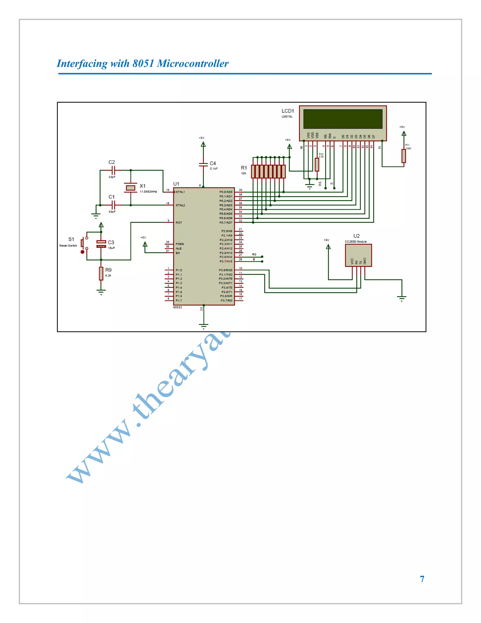
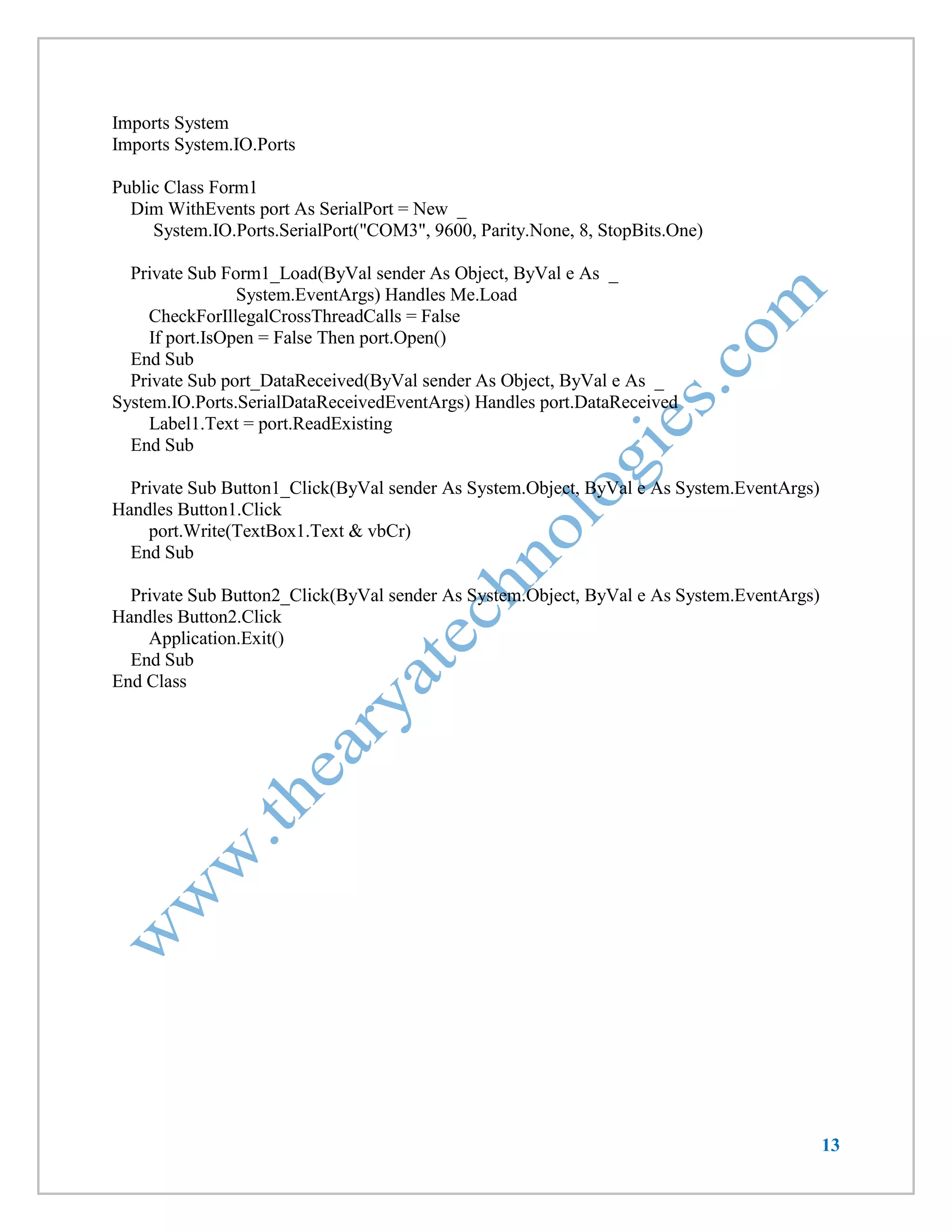
Code
LCD will display data received & send string “received” as an acknowledgement. Here baud rate setting is 9600.
#include<reg52.h>
#include <string.h>
#define cmdport P2
#define dataport P0
unsigned char ntc[32];
unsigned char current_byte = 0;
unsigned char icnt = 0;
sbit rs = cmdport^6; //register select pin
//sbit rw = cmdport^1; // read write pin
sbit e = cmdport^7; //enable pin
void ser_init(void);
void Delay250us (void);
void MsDelay (int n);
void read_ntc(void);
void lcdcmd(unsigned char item);
void lcddata(unsigned char item);
void lcdstr(unsigned char *s);
void lcdinit(void);
void Delay250us (void)
{
int j ;
for(j = 0 ; j < 100 ; j ++)
{
}
}
void MsDelay (int n)
{
int j ;
for(j = 0 ; j < n ; j ++)
{
Delay250us() ;
Delay250us() ;
Delay250us() ;
Delay250us() ;
}
}
void ser_init(void)
{
TMOD=0x20; //Timer 1 Mode 2](https://image.slidesharecdn.com/atk2-140918051600-phpapp01/75/CC2500-Wireless-Trans-receiver-Module-8-2048.jpg)
![9
TH1=-3; // Bouad Rate-9600
SCON=0x050; // 8 bit,1 stop bit
TR1=1; // start timer
ES = 1; // enable serial interrupts
}
void recieve() interrupt 4 using 1 // Function to recieve data serialy from RS232
{
if (RI)
{
ntc[ current_byte]=SBUF;
RI=0;
current_byte++;
}
}
void Ser_Write_Text(unsigned char *str)
{
unsigned char l,i;
l = strlen(str)+1; // get the length of string
for(i=1;i<l;i++)
{
SBUF=*str; // send every char one by one
while(TI==0);
TI=0;
str++;
}
}
void ser_write_no(unsigned int no)
{
SBUF=no;
while(TI==0);
TI=0;
}
void read_ntc(void) // Function to display the received string
{
unsigned char count;
lcdcmd(0x01);
MsDelay(10);
lcdcmd(0x80);
MsDelay(10);
for(count=0;count<current_byte;count++)
{
lcddata(ntc[count]);](https://image.slidesharecdn.com/atk2-140918051600-phpapp01/75/CC2500-Wireless-Trans-receiver-Module-9-2048.jpg)

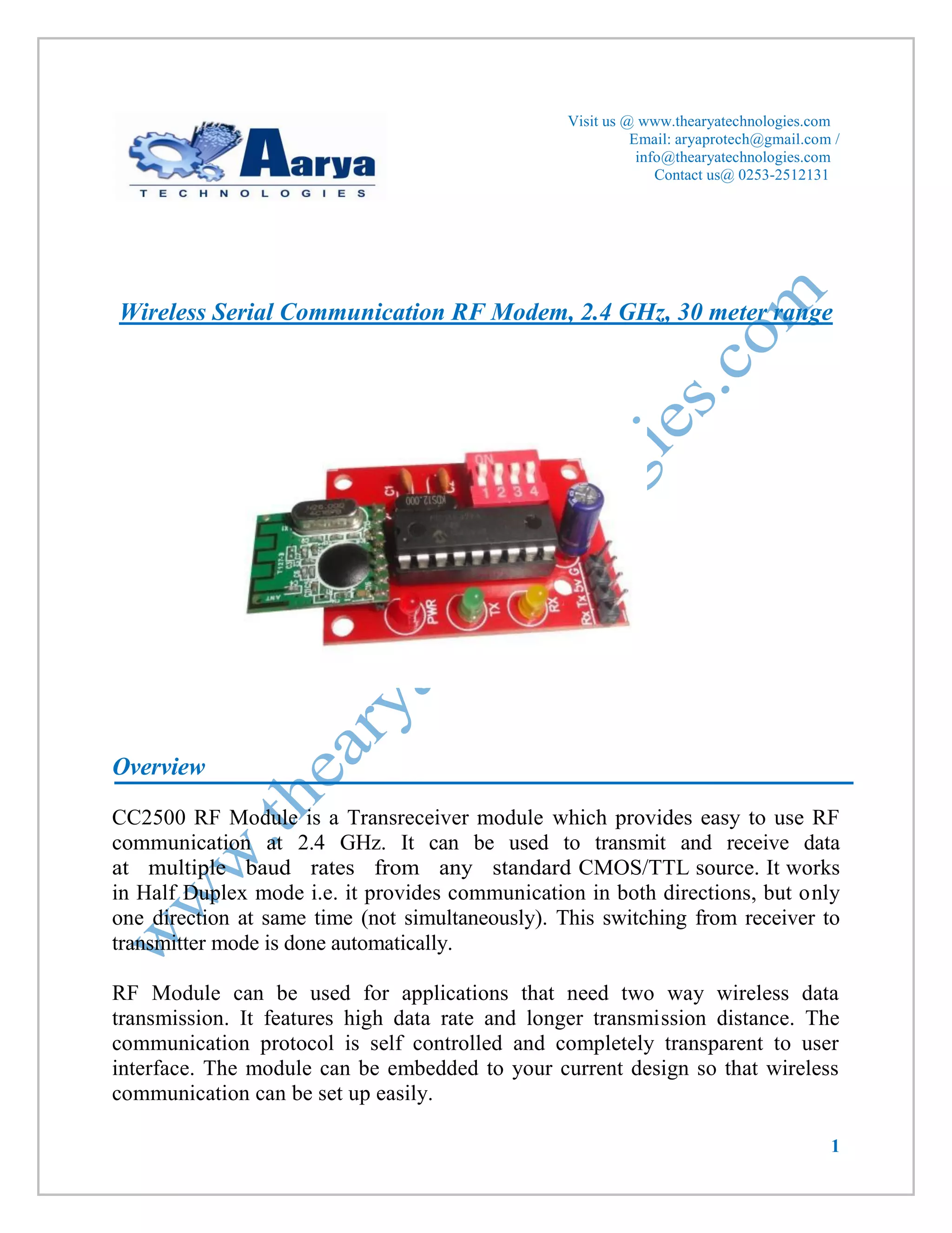
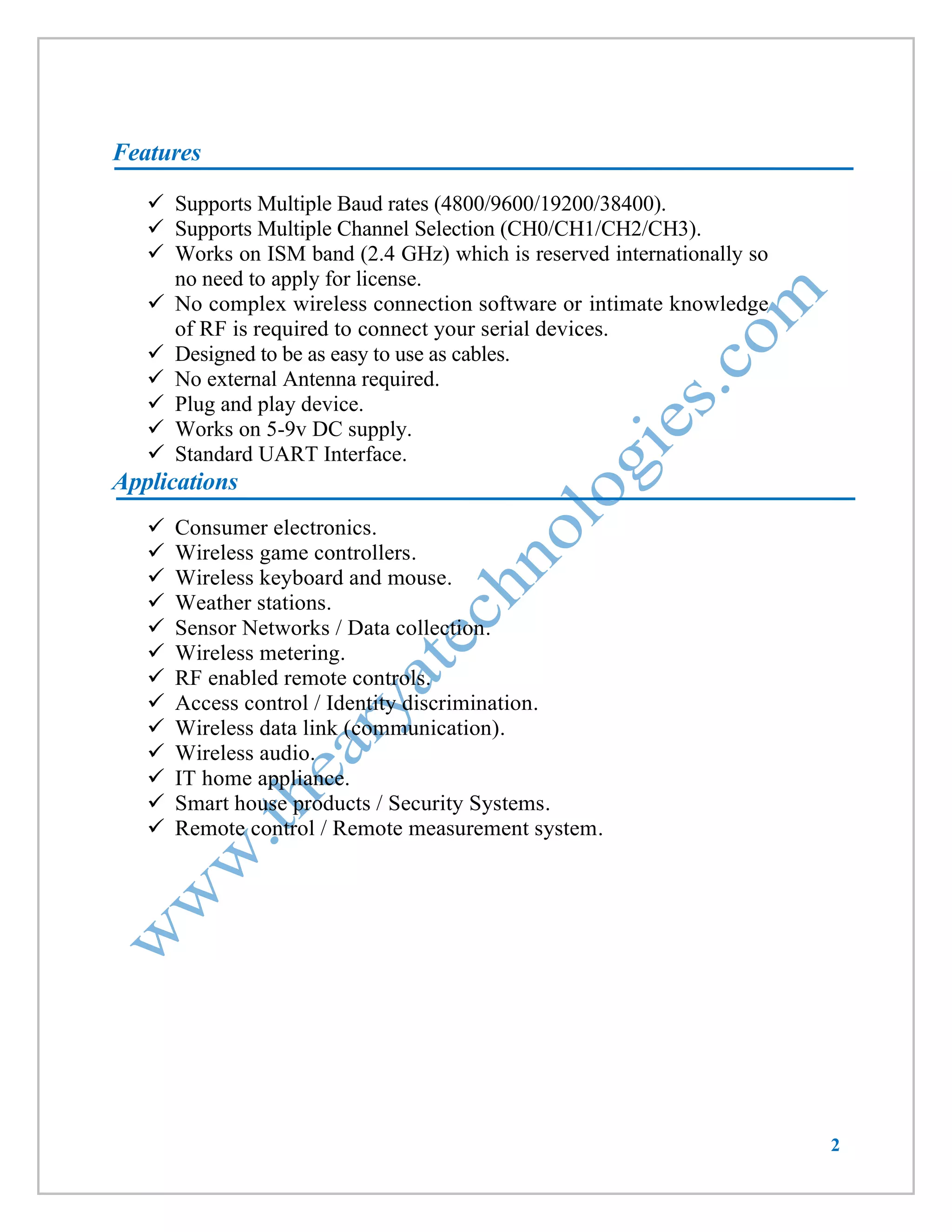
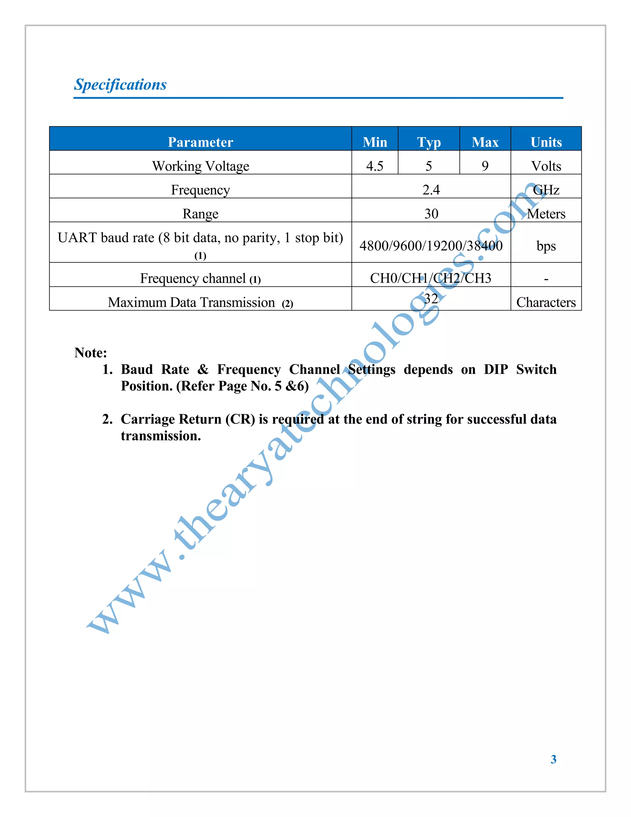
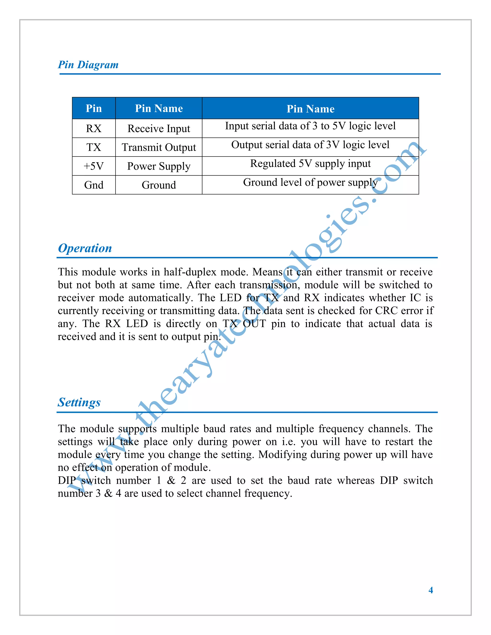
This document provides information about a wireless serial communication RF modem module that operates at 2.4 GHz with a range of 30 meters. It can transmit and receive data at multiple baud rates and supports half-duplex communication. The module has features such as multiple channel selection, compatibility with the unlicensed 2.4 GHz ISM band, and plug-and-play operation. Specifications, pinouts, operating instructions, and code examples for interfacing the module with an 8051 microcontroller and PC are also included.