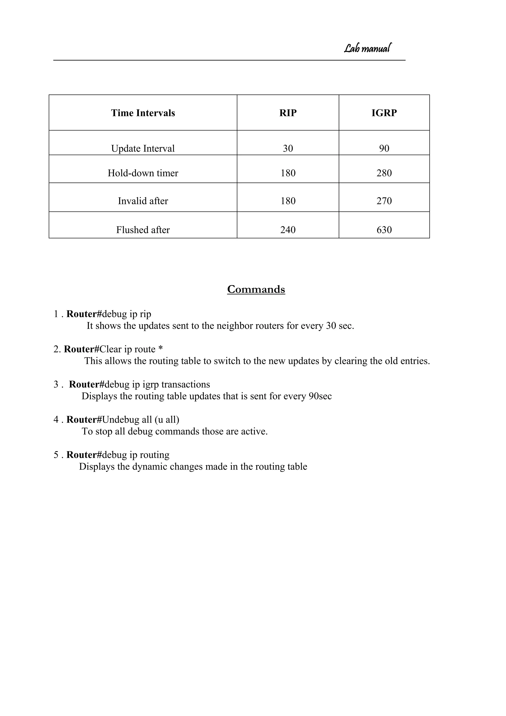
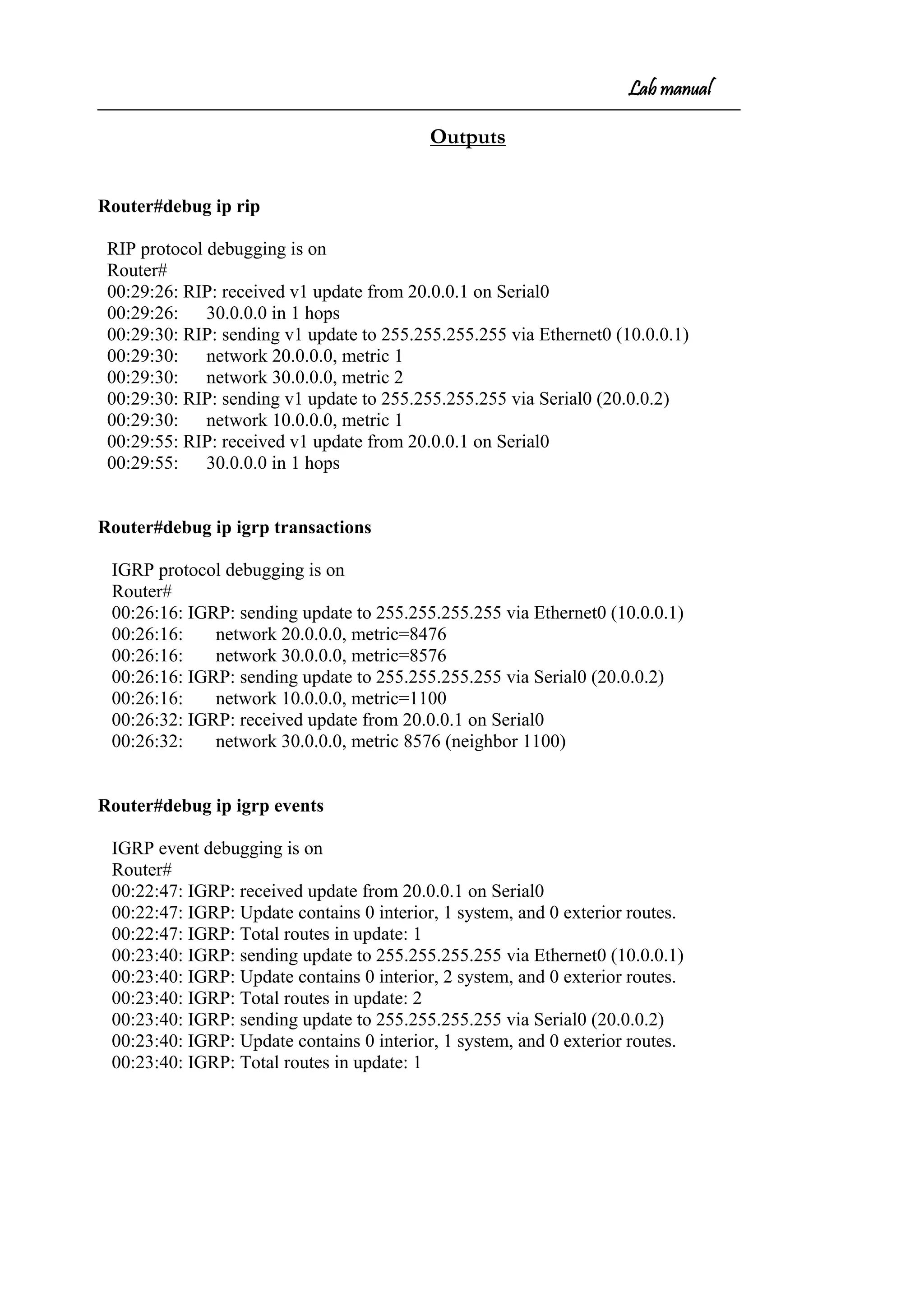
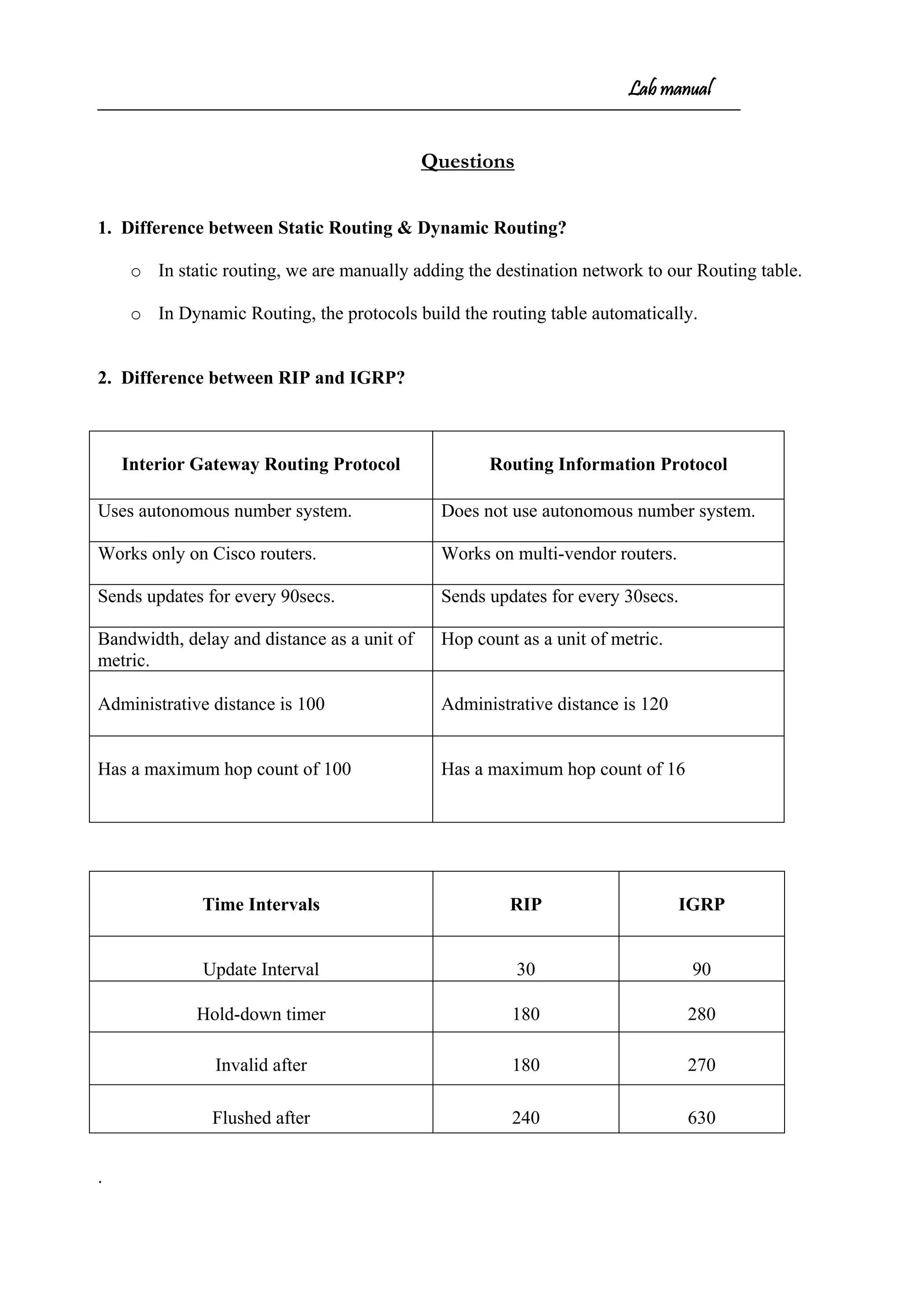
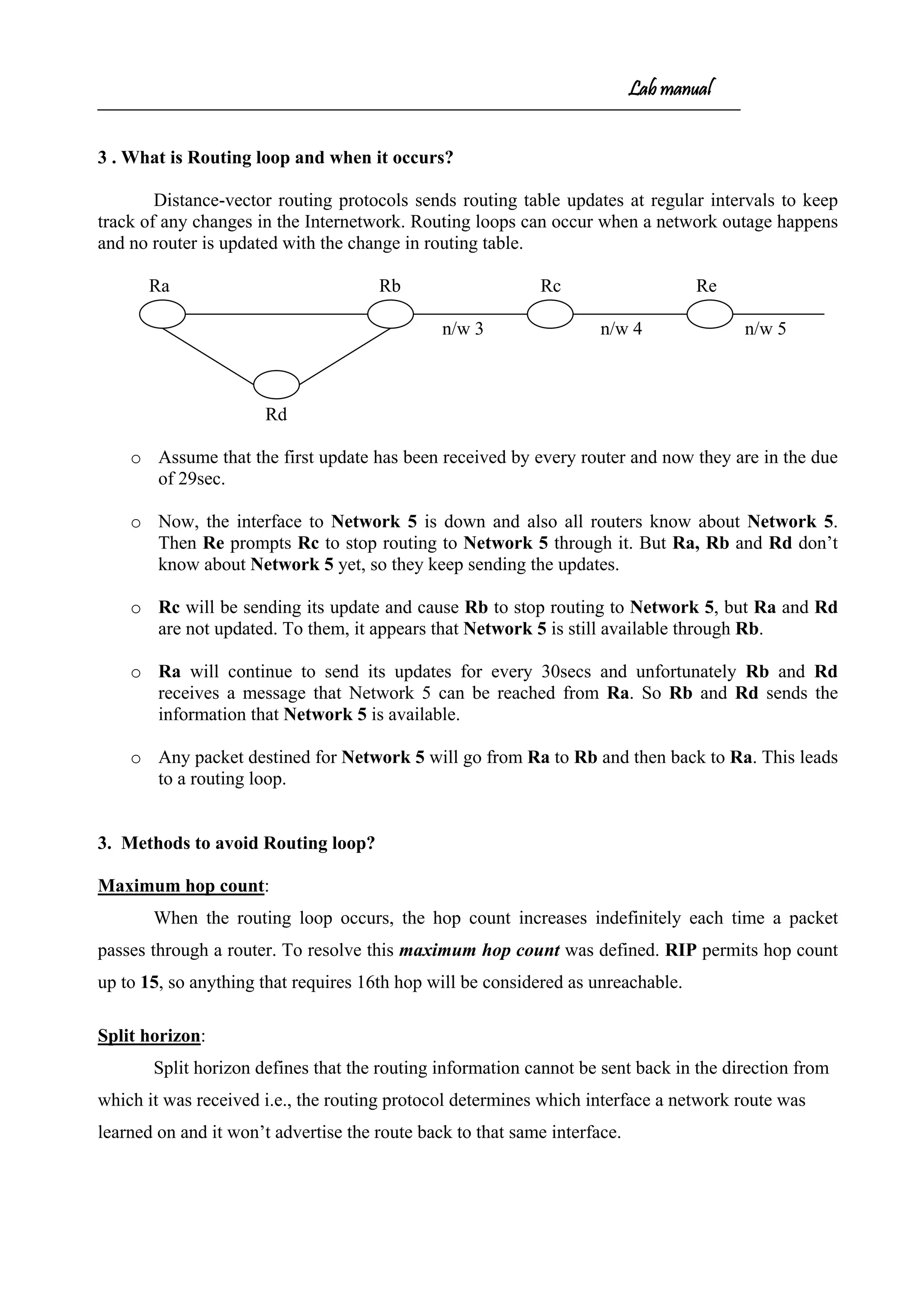
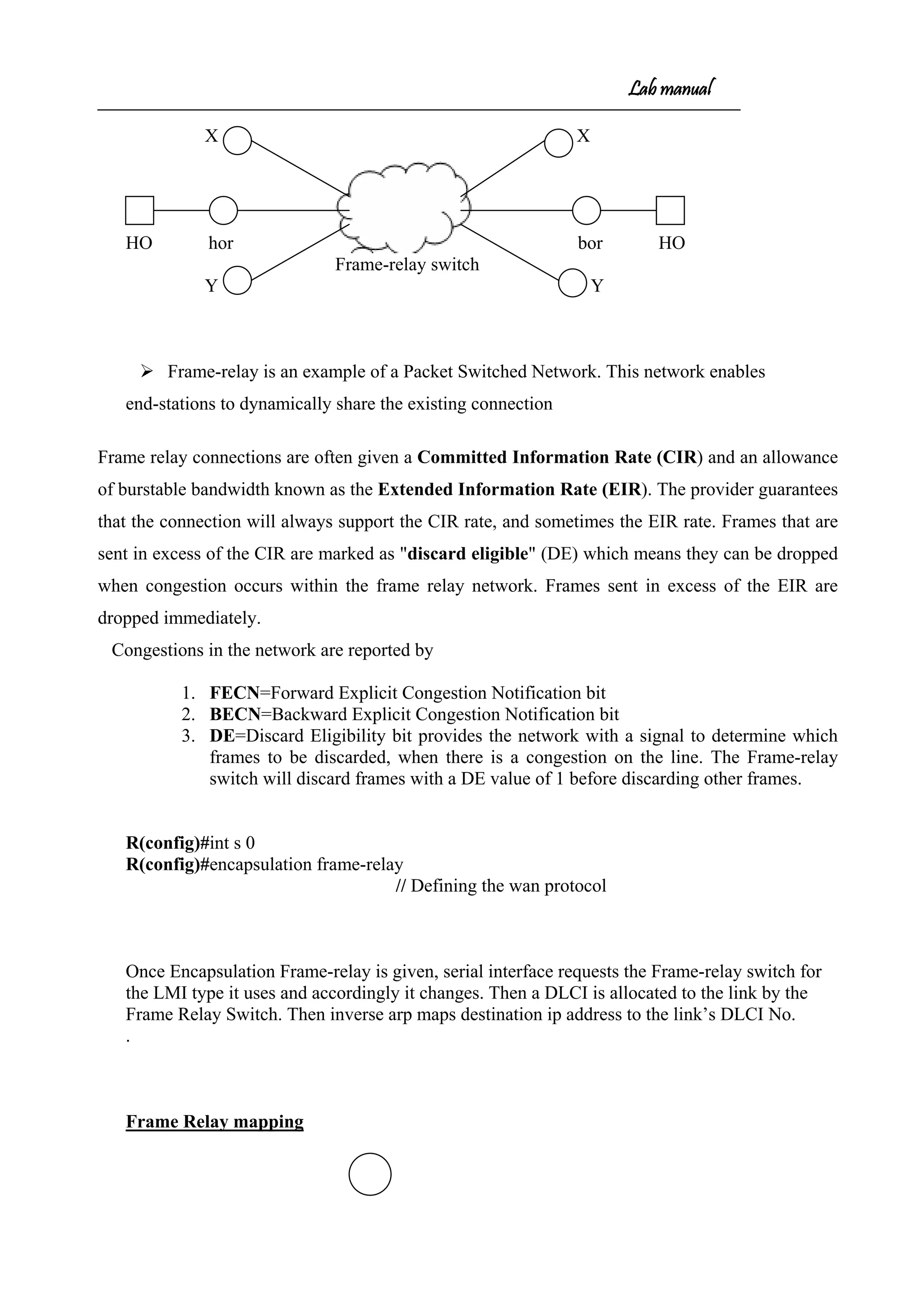
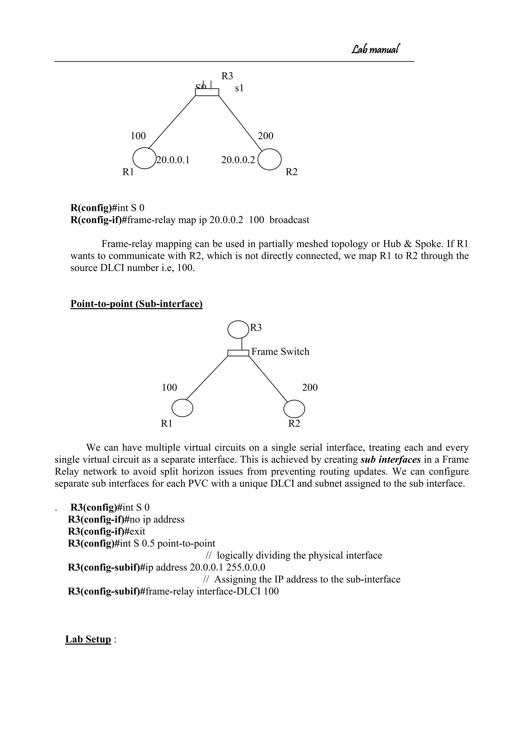
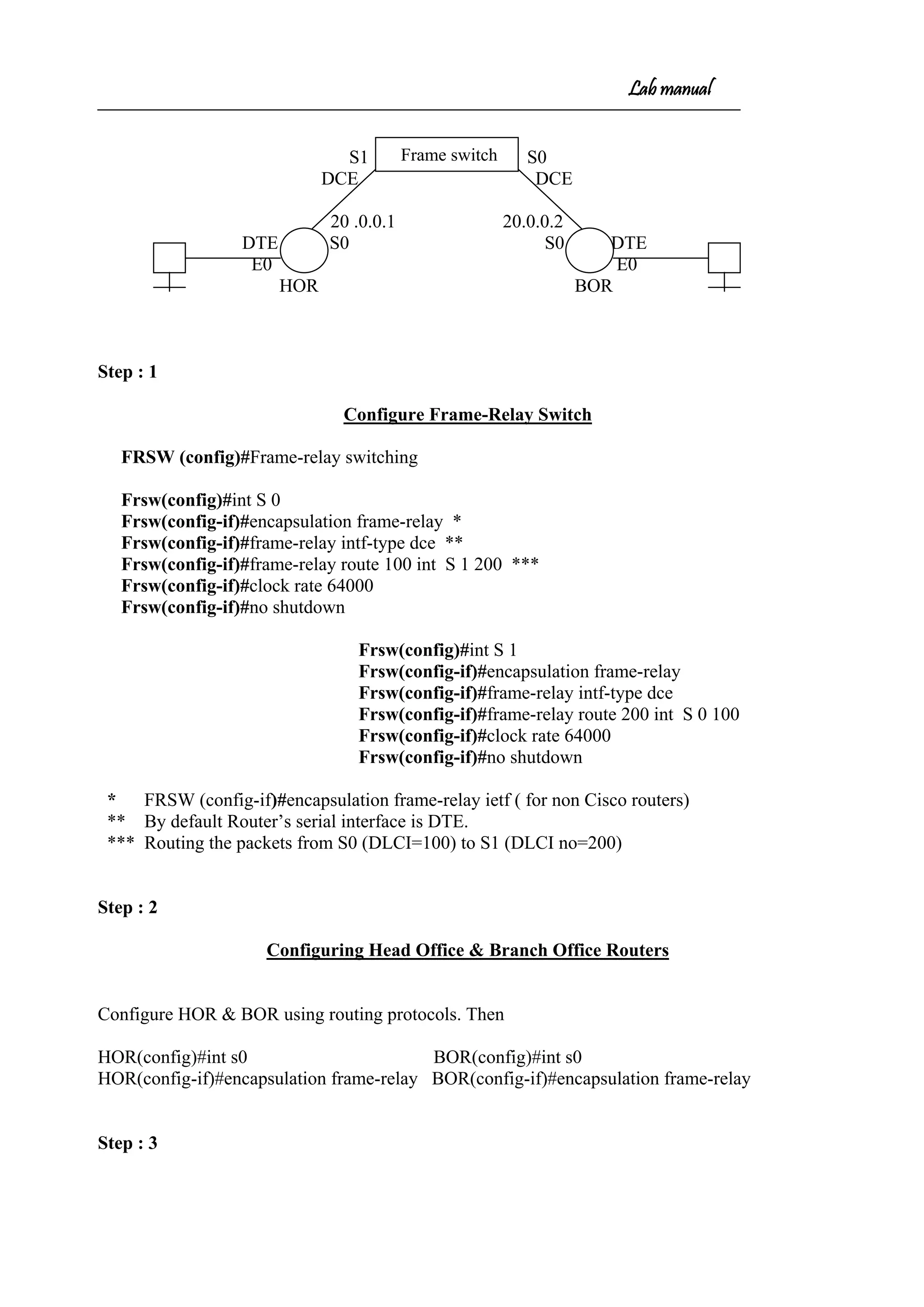
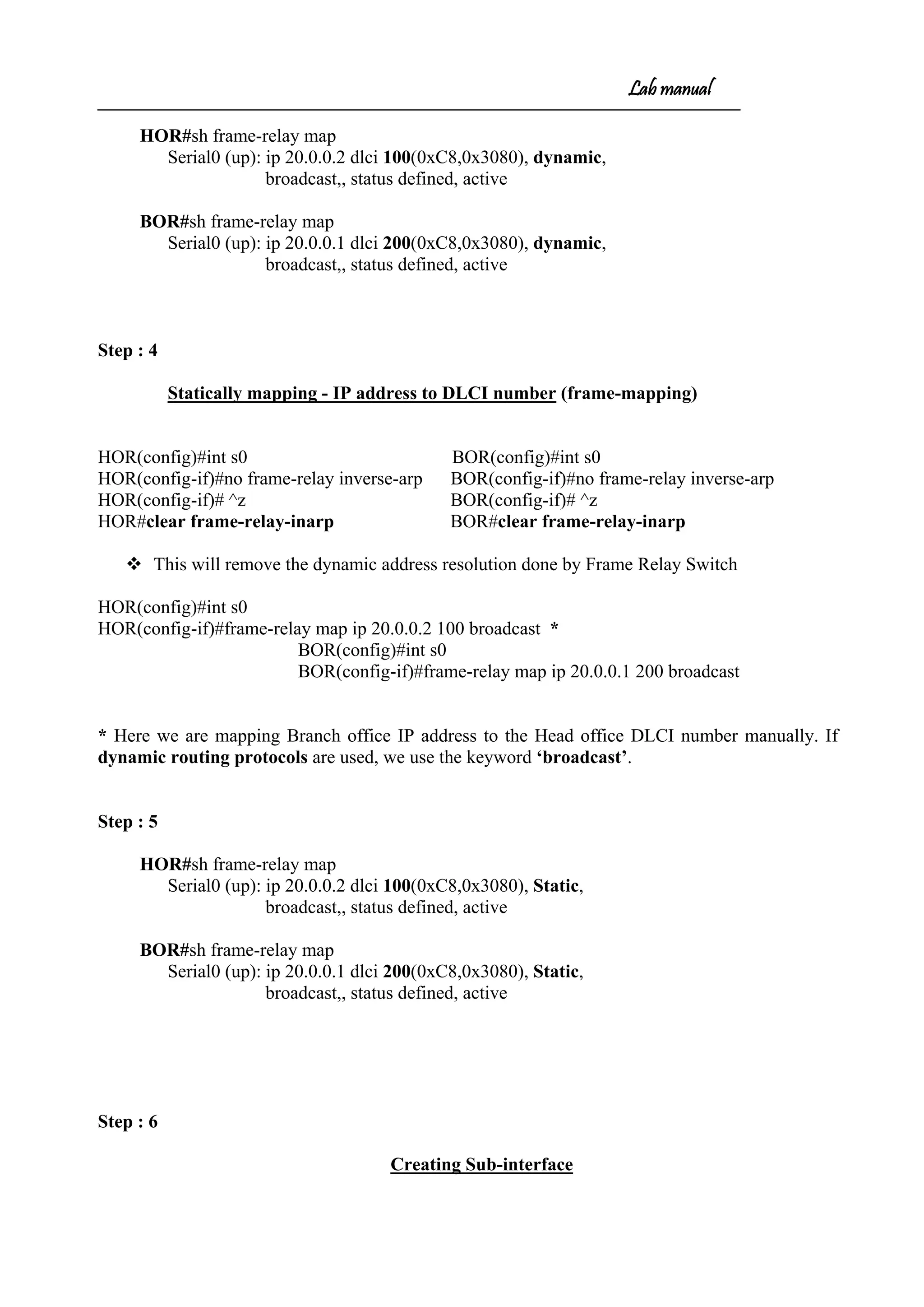
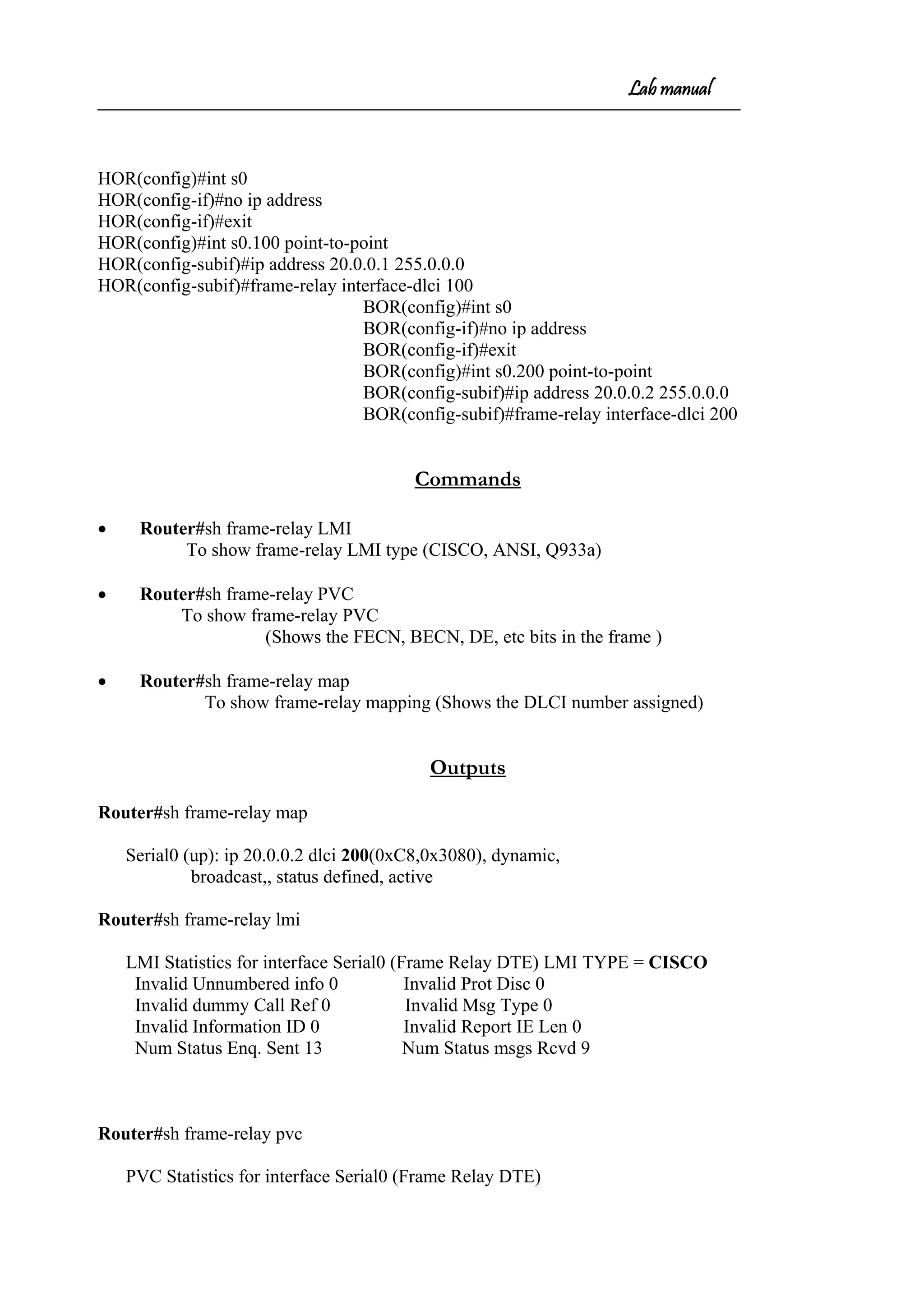
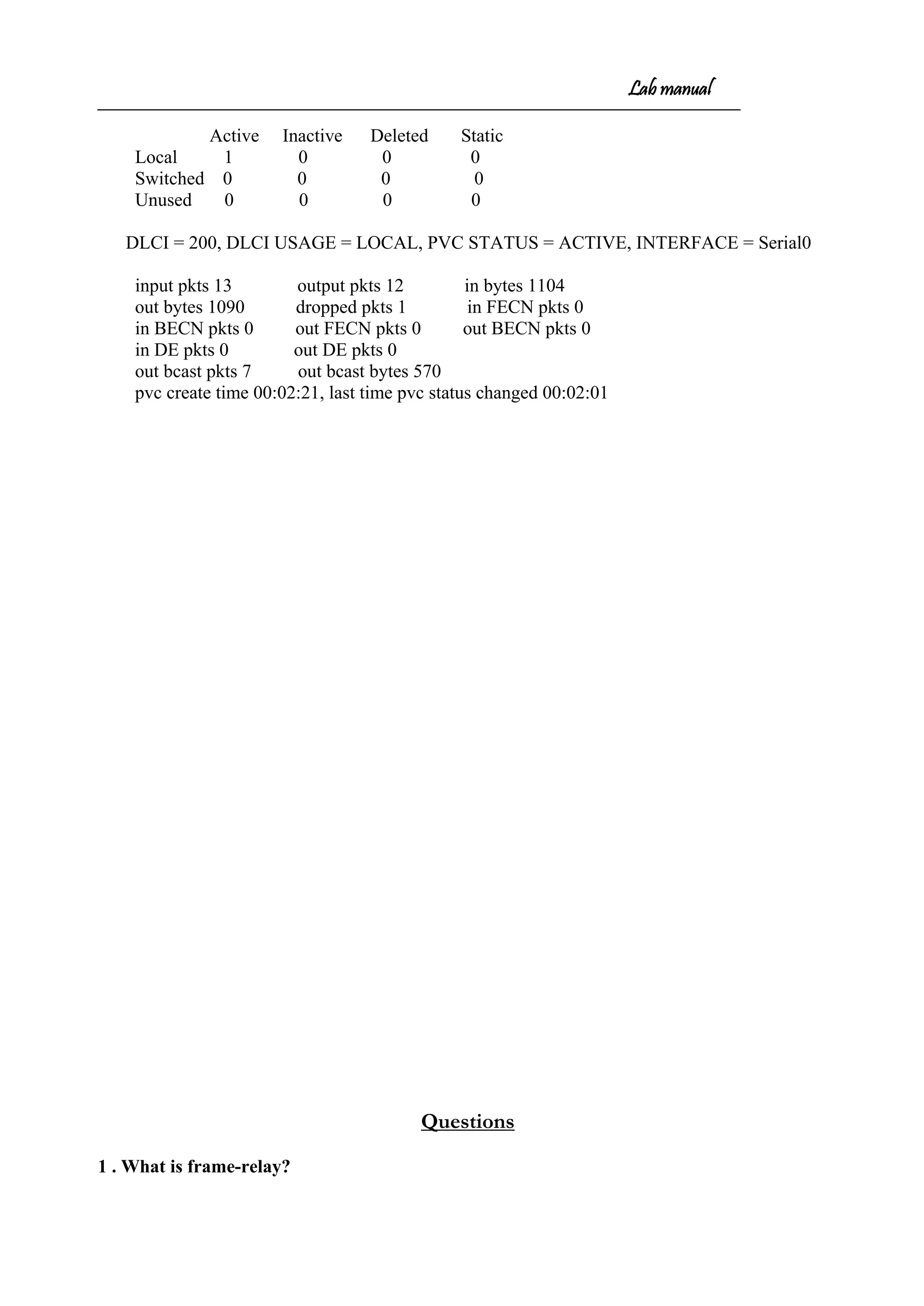
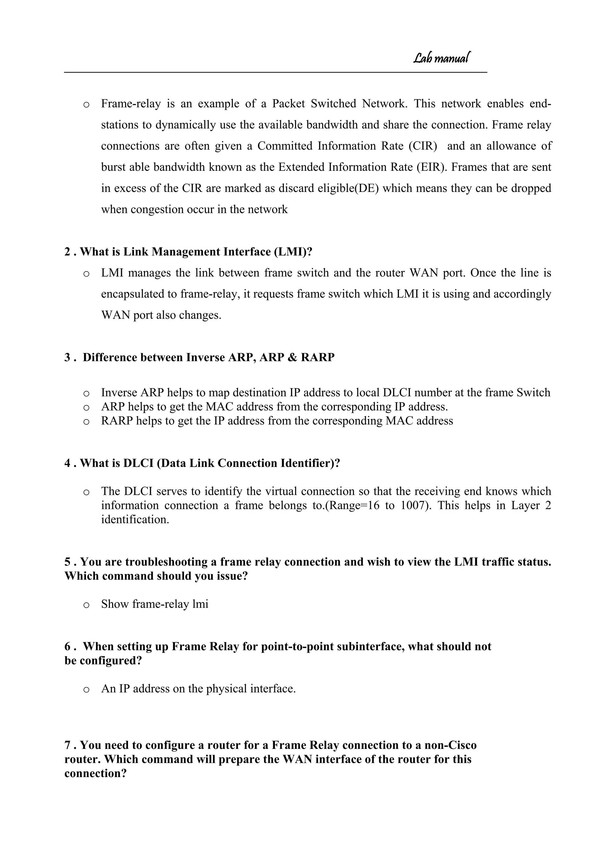
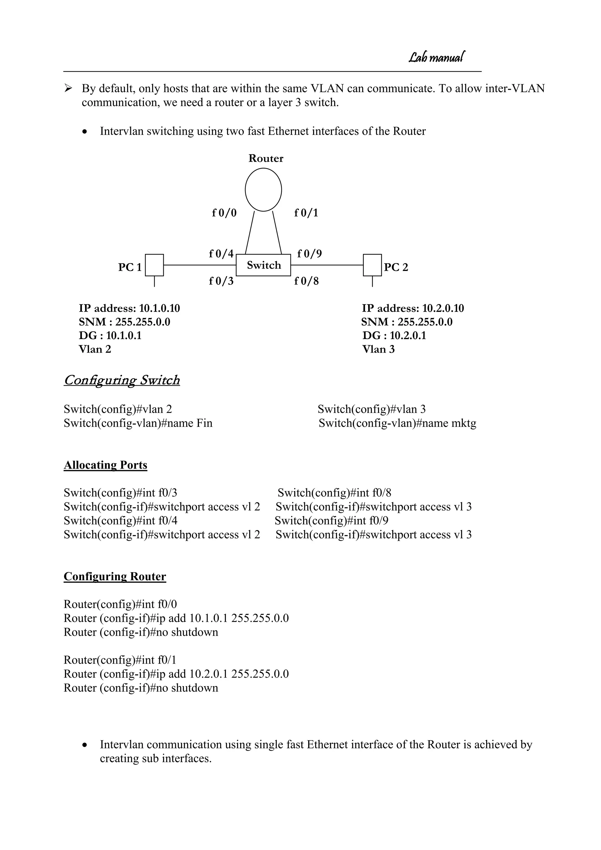
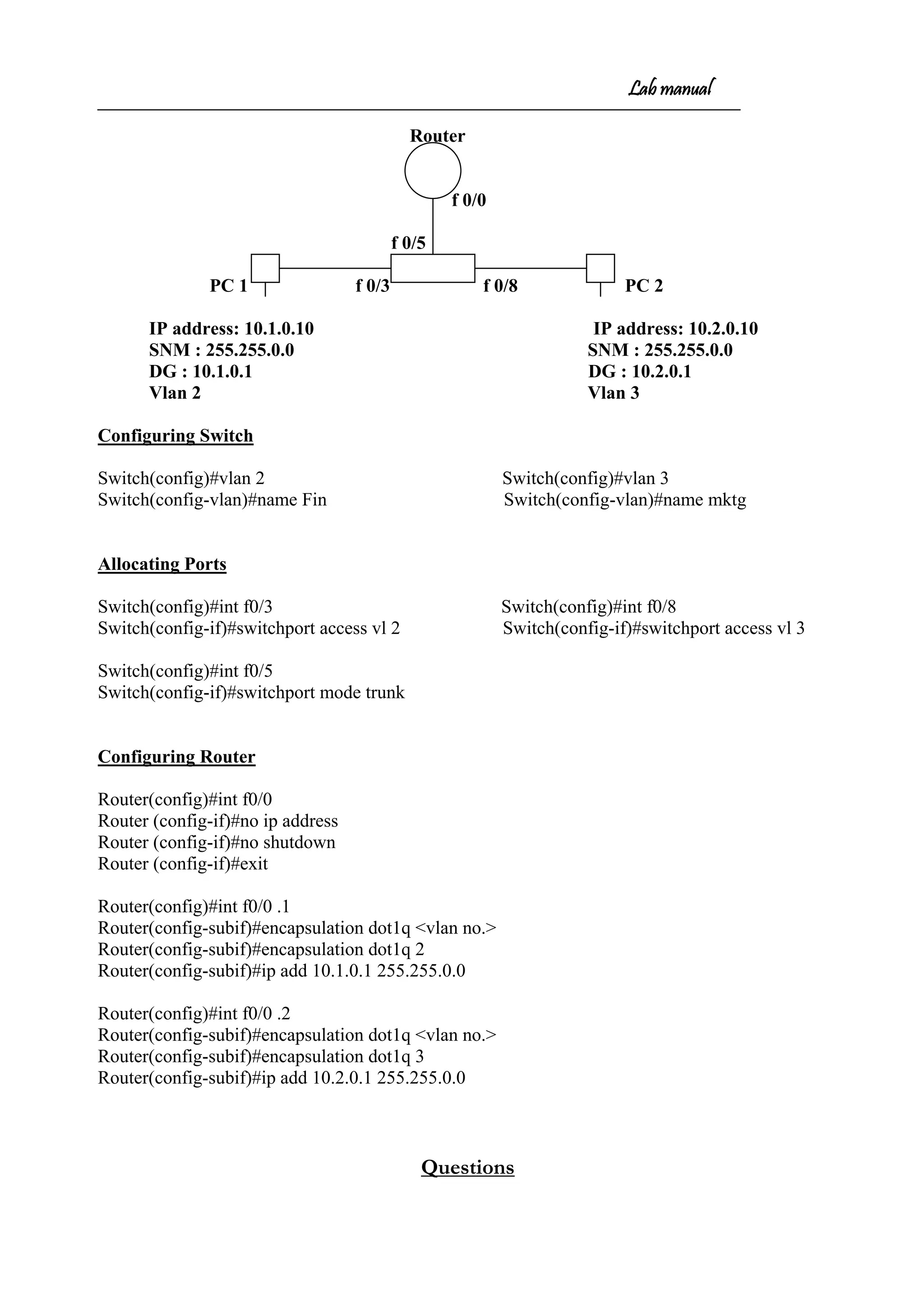
Downloaded 51 times
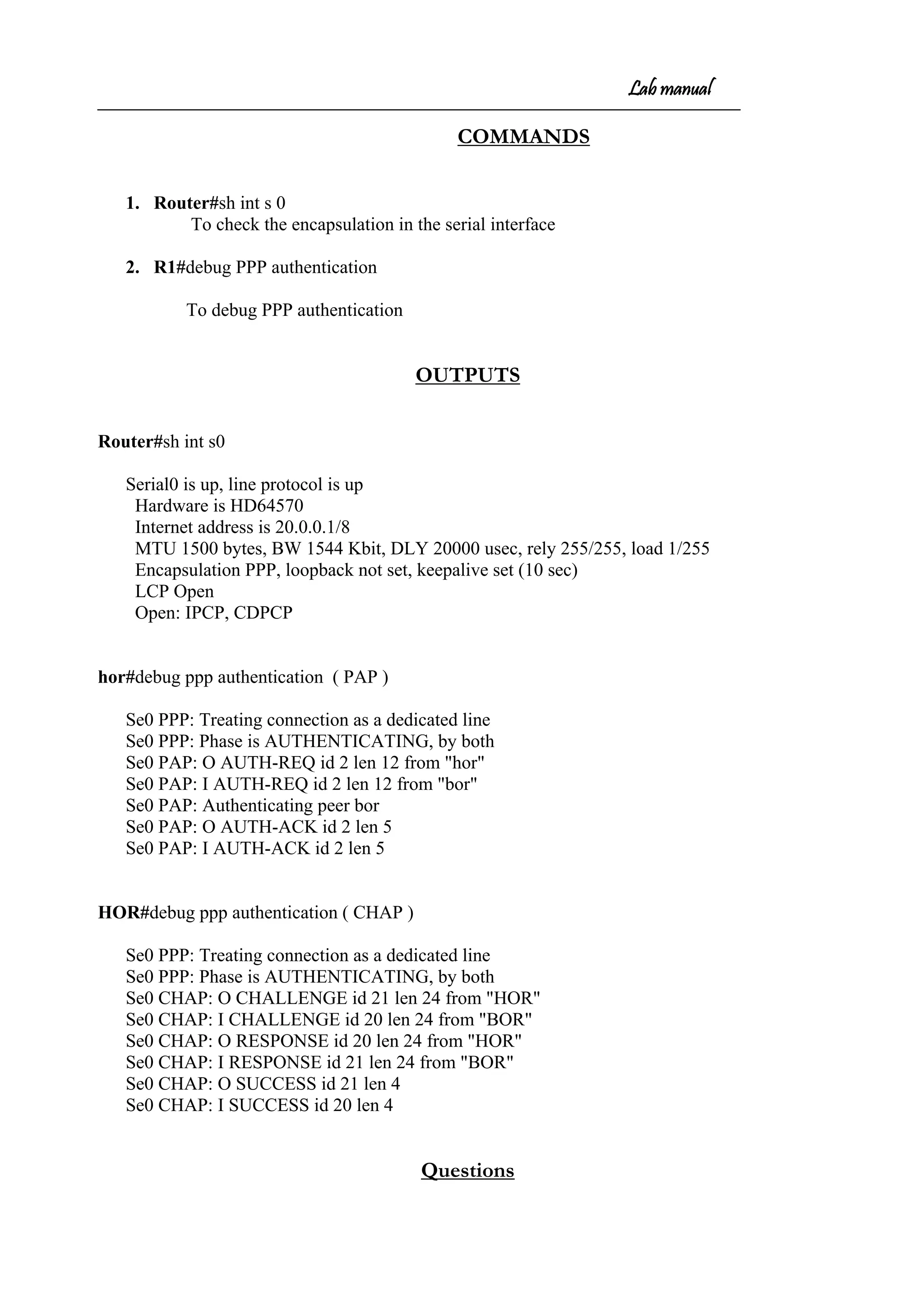
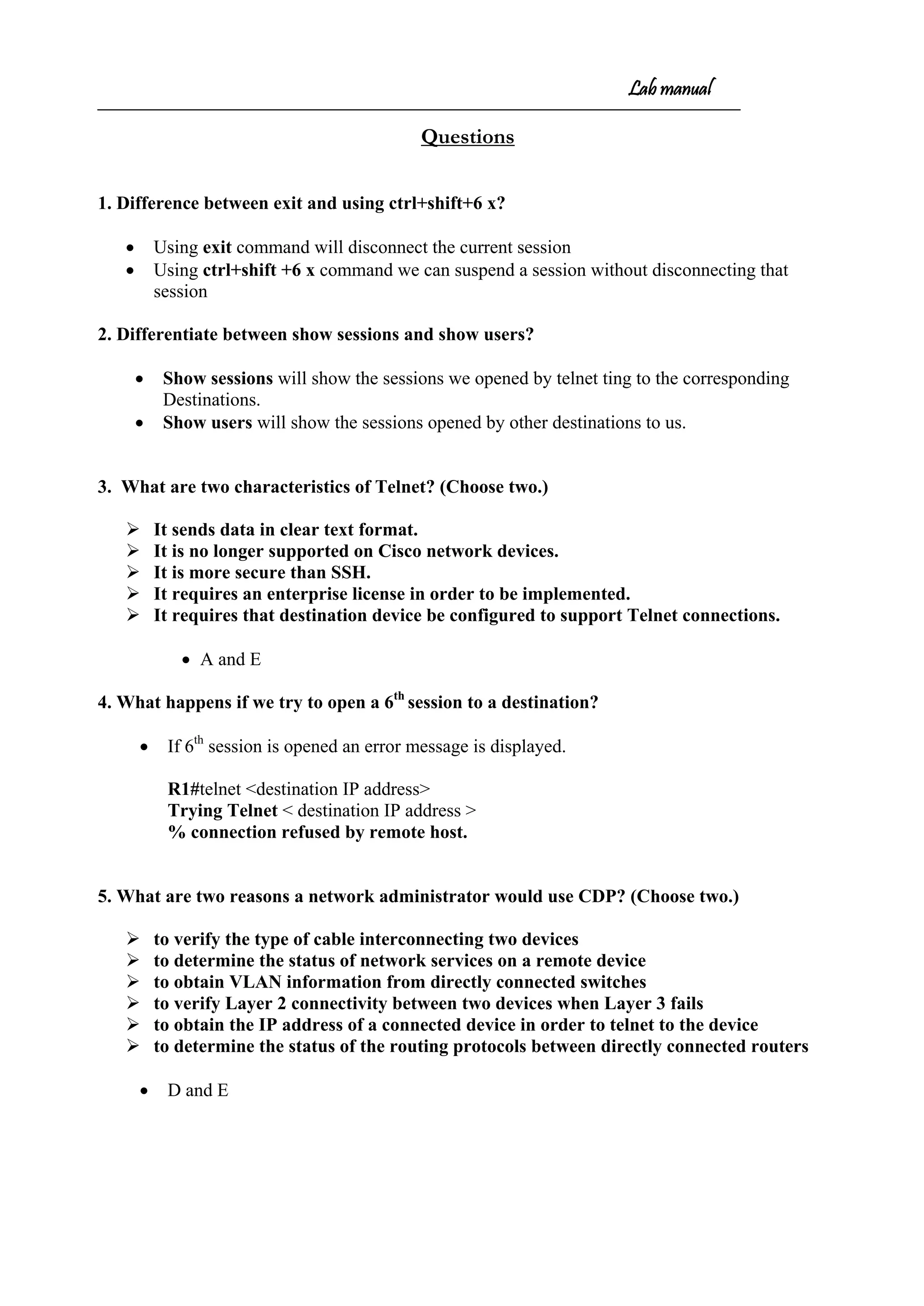
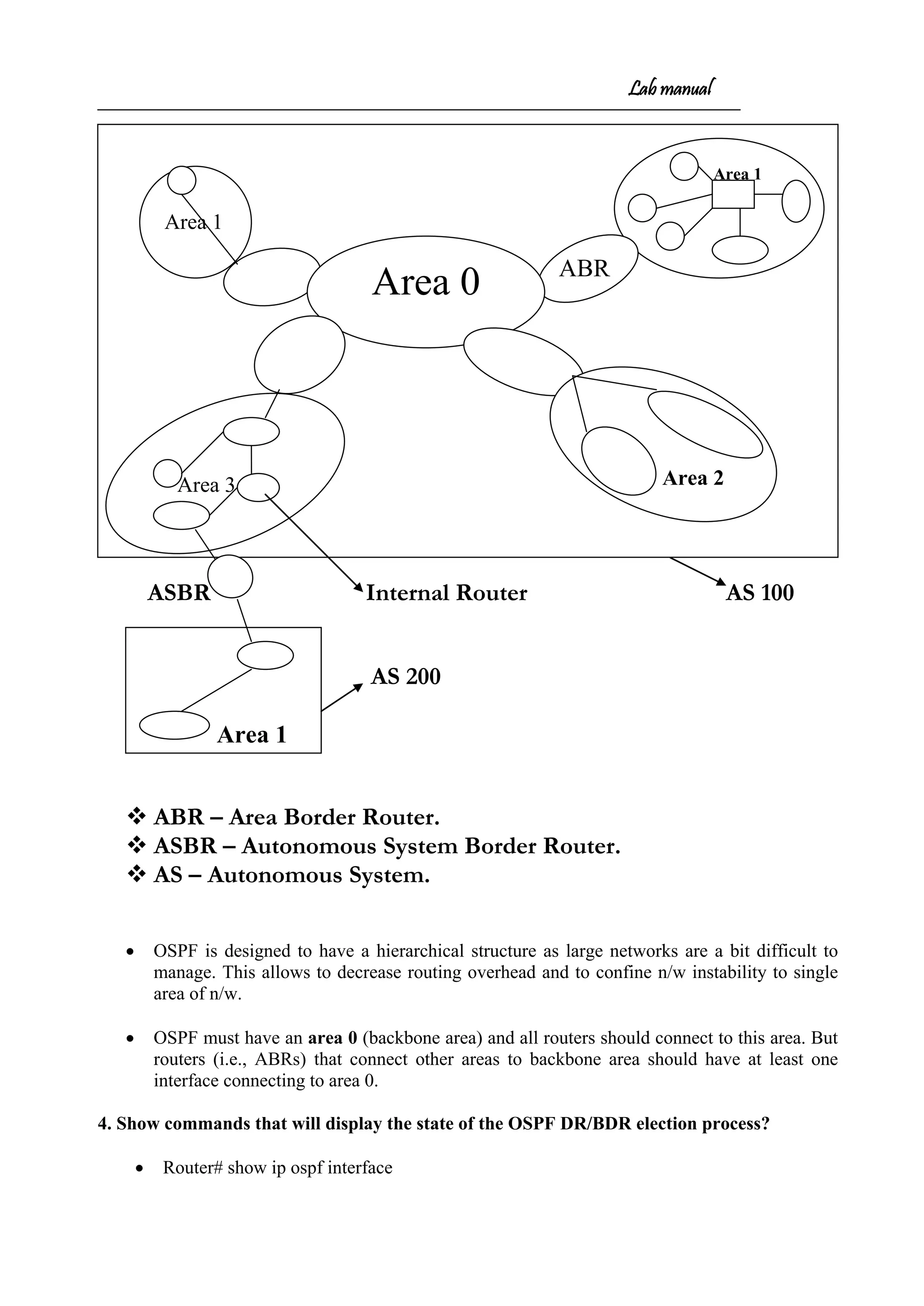
![Lab manual
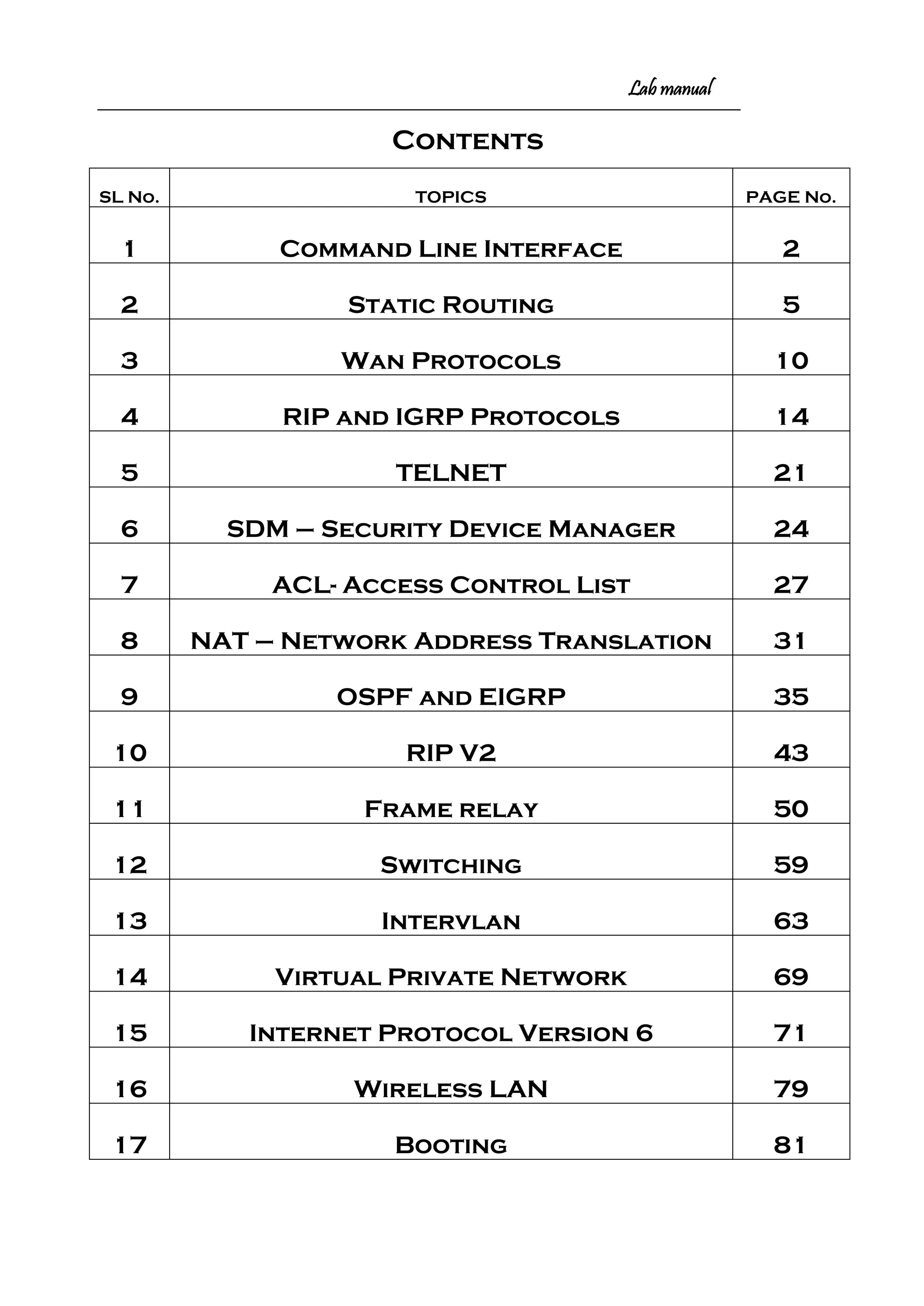
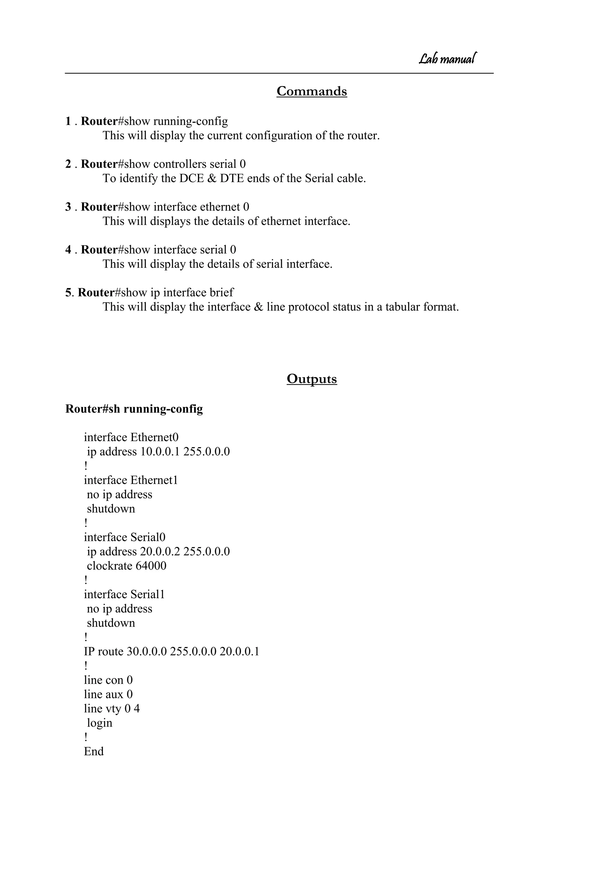
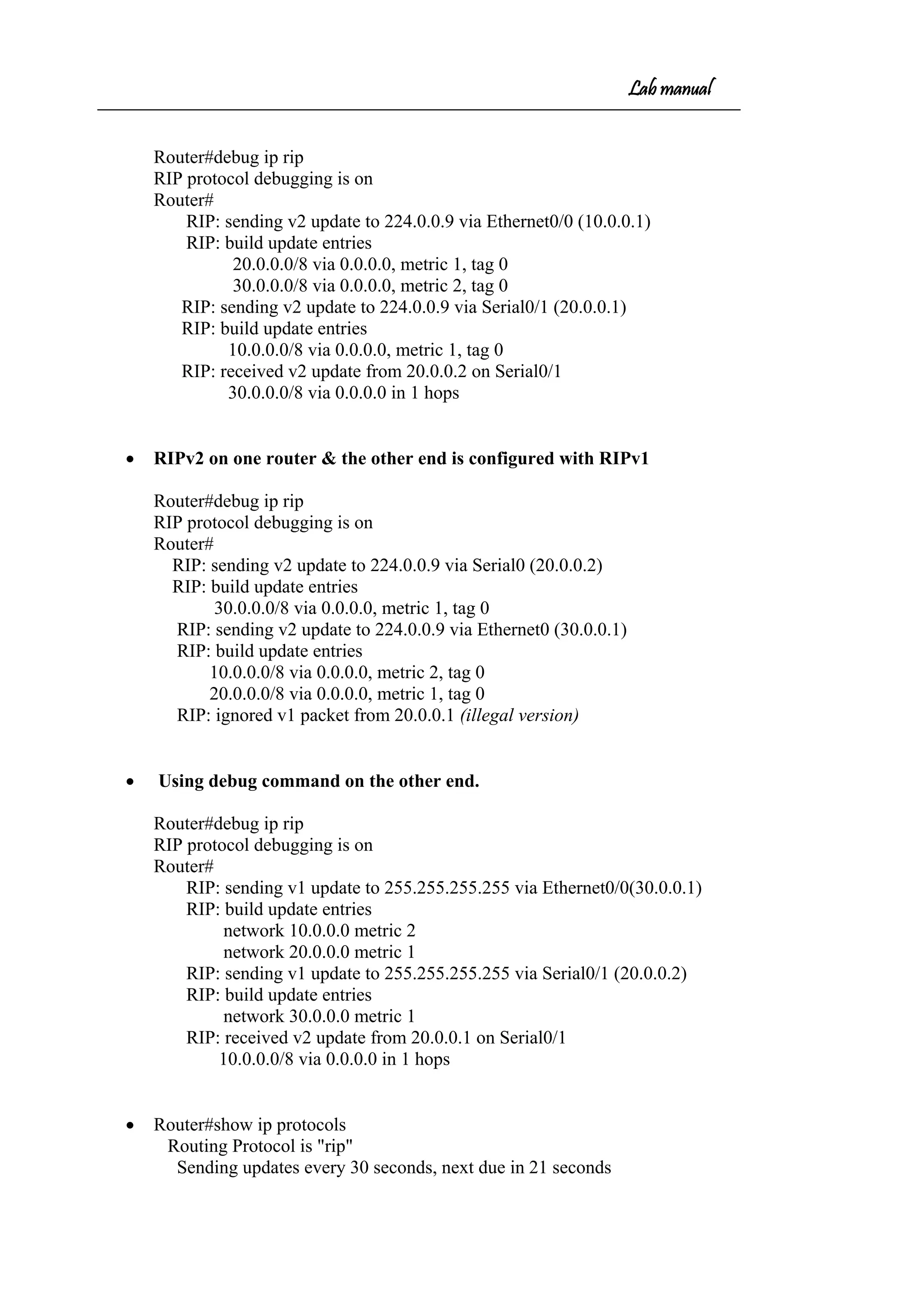
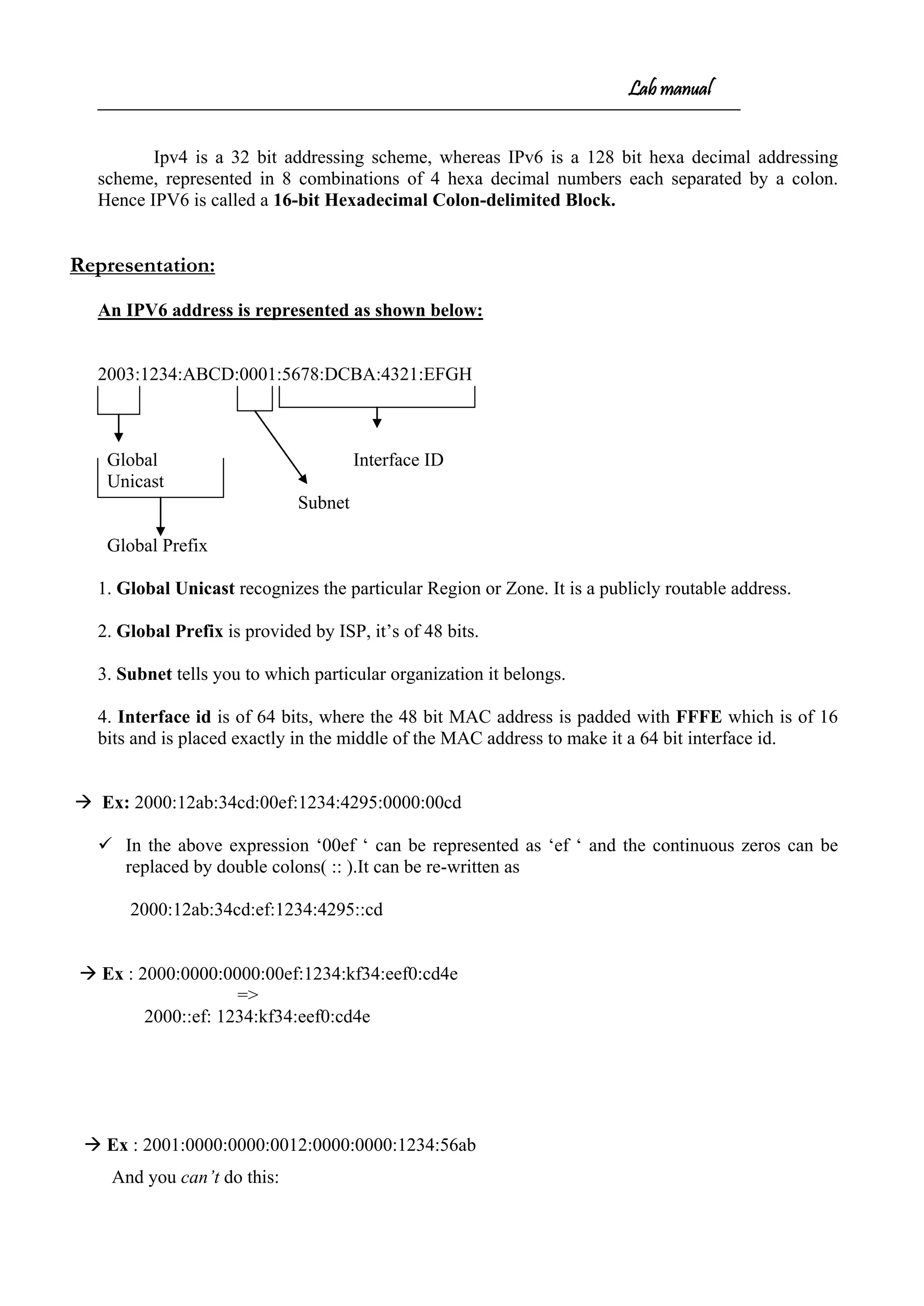
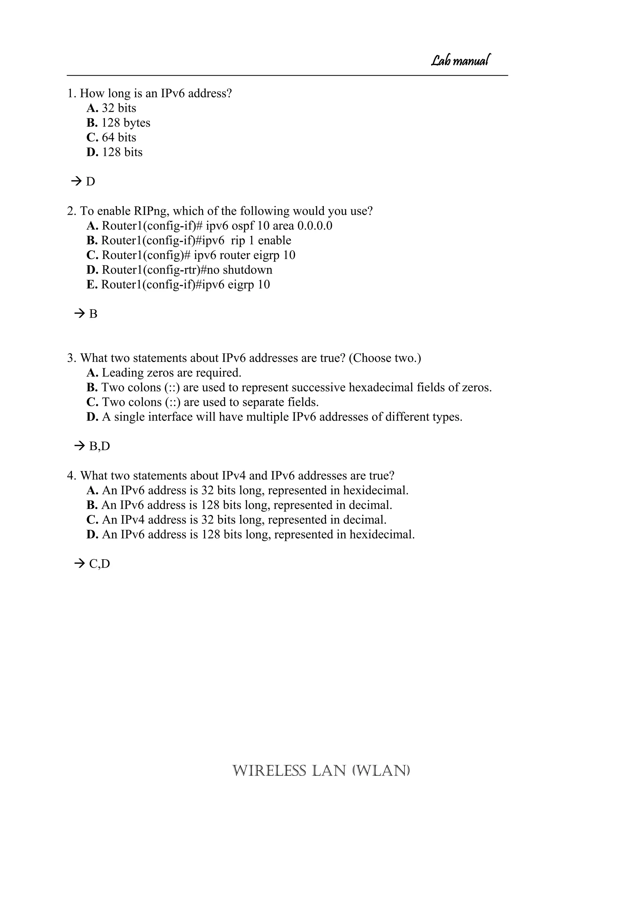
COMMAND LINE INTERFACE (CLI)
• To enter the hyper terminal
Programs Accessories Communication HyperTerminal
(HyperTerminal window opens)
-prompts for the screen name (not the router name)
-connect to window select com1 ok
-com1 properties window select restore default ok
• Switch ON the router (if new router that is not configured it will ask -----
Would u like to enter initial configuration dialog[yes/no]: no
Press return to get started (enter)
Router>
* User Mode/User Executable Mode
Router> enable (enter)
Router#
* Privileged Mode/Enable Mode – Executable Mode.
The following commands can be executed in this mode
Router#show running-config(enter)
Router#debug xxx
Router#copy xxx
Router#configure terminal(enter)
Router(config)#
* Global Configuration Mode - Any configuration change in this mode affects the
whole router.
Router(config)#interface e 0/fastethernet 0/ S0 / S 1(enter)
Router(config-if)#
* Specific Configuration Mode – configuration changes to specific part of the
router like lines and interfaces.](https://image.slidesharecdn.com/labmannual-140804000750-phpapp02/75/Labmannual-2-2048.jpg)
![Lab manual
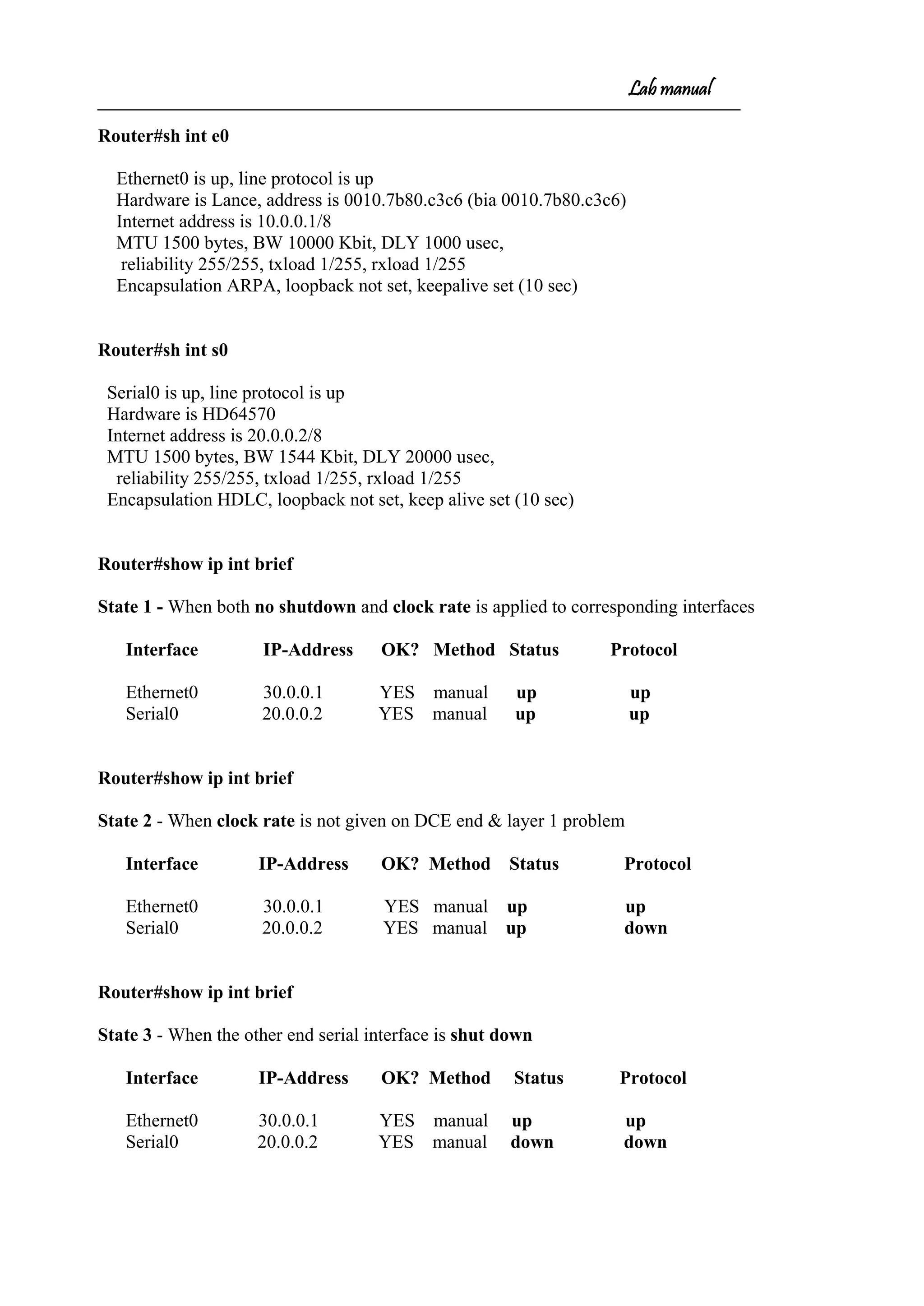
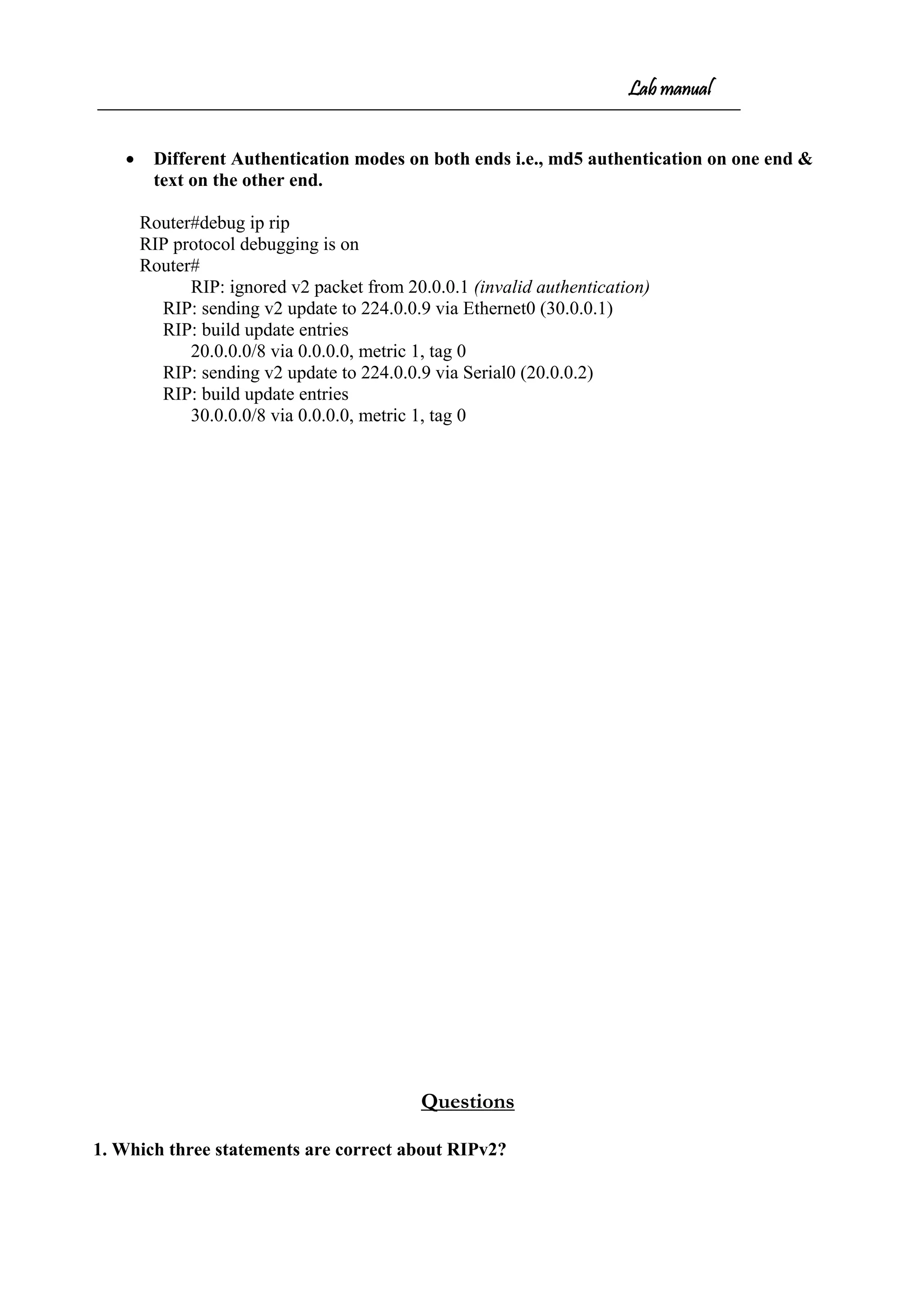
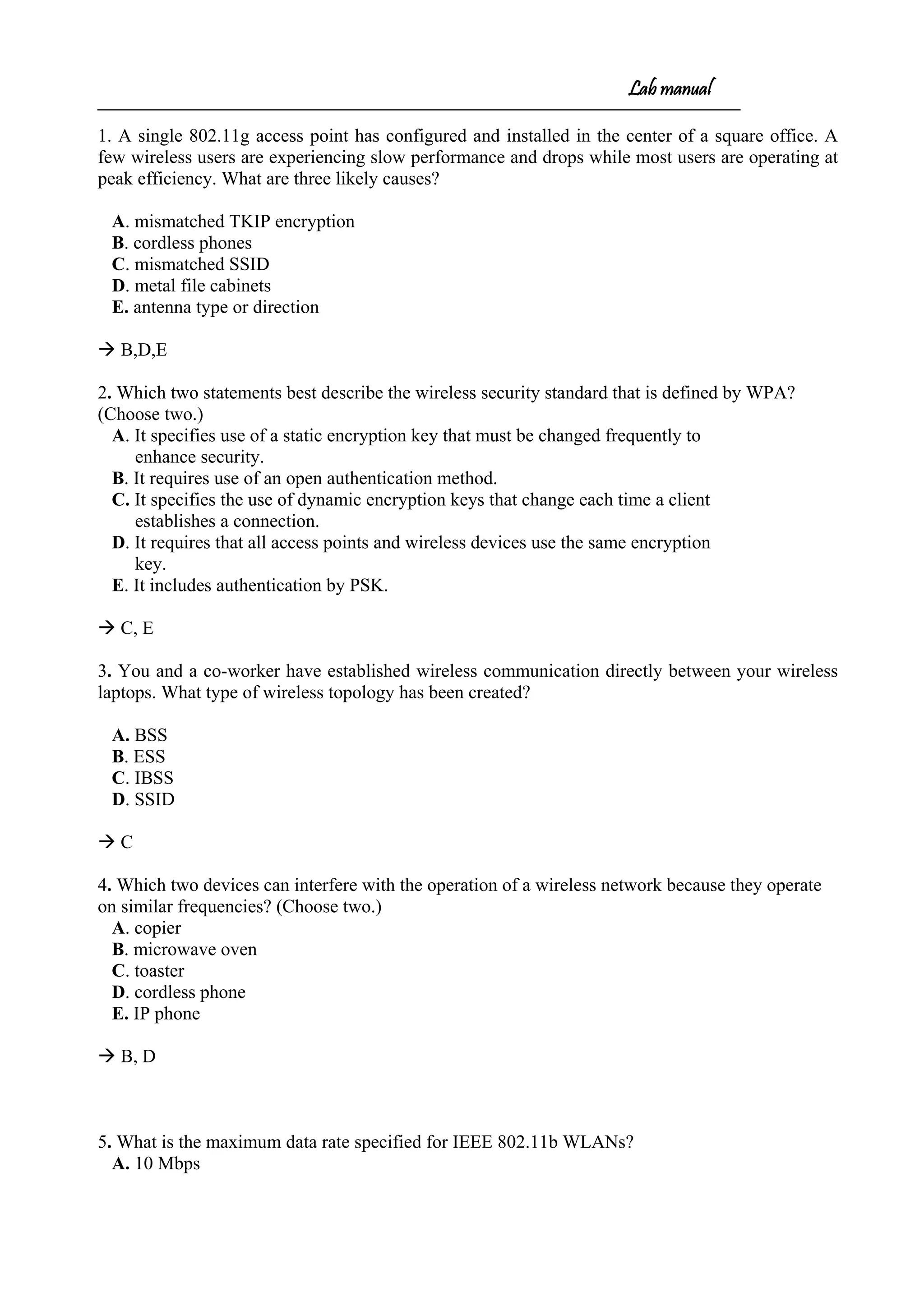
Router#show controllers s 0
HD unit 0, idb = 0xB883C, driver structure at 0xBDB98
buffer size 1524 HD unit 0, V.35 DCE cable, clockrate 64000
Router#show ip route
Codes: C - connected, S - static, I - IGRP, R - RIP, M - mobile, B - BGP
D - EIGRP, EX - EIGRP external, O - OSPF, IA - OSPF inter area
N1 - OSPF NSSA external type 1, N2 - OSPF NSSA external type 2
i - IS-IS, L1 - IS-IS level-1, L2 - IS-IS level-2, * - candidate default
Gateway of last resort is not set
C 20.0.0.0/8 is directly connected, Serial0
C 10.0.0.0/8 is directly connected, Ethernet0
S 30.0.0.0/8 [1/0] via 20.0.0.1
Router#sh protocols
Global values:
Internet Protocol routing is enabled
Ethernet0 is up, line protocol is up
Internet address is 10.0.0.1/8
Ethernet1 is administratively down, line protocol is down
Serial0 is up, line protocol is up
Internet address is 20.0.0.2/8
Serial1 is administratively down, line protocol is down](https://image.slidesharecdn.com/labmannual-140804000750-phpapp02/75/Labmannual-8-2048.jpg)
![Lab manual
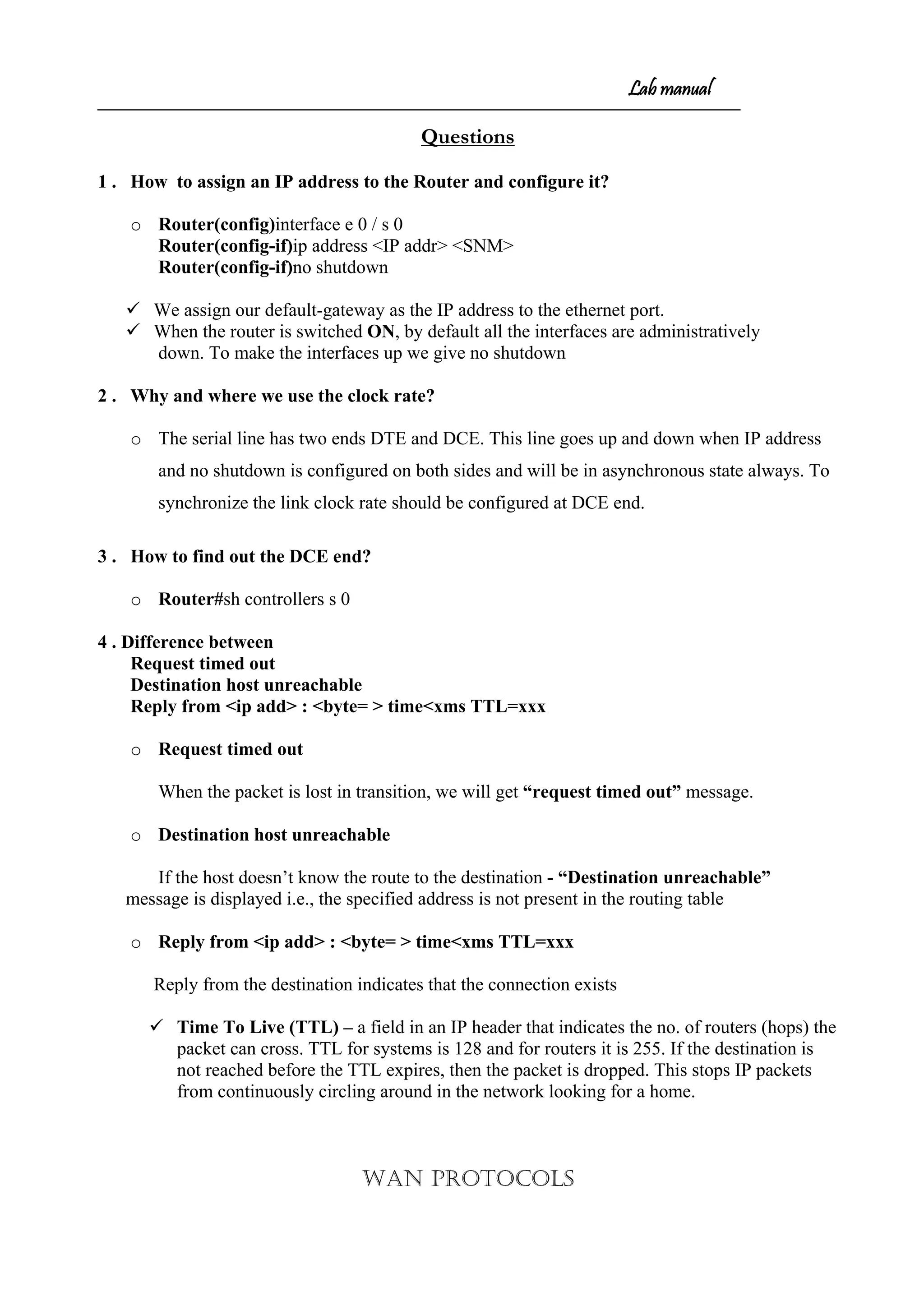
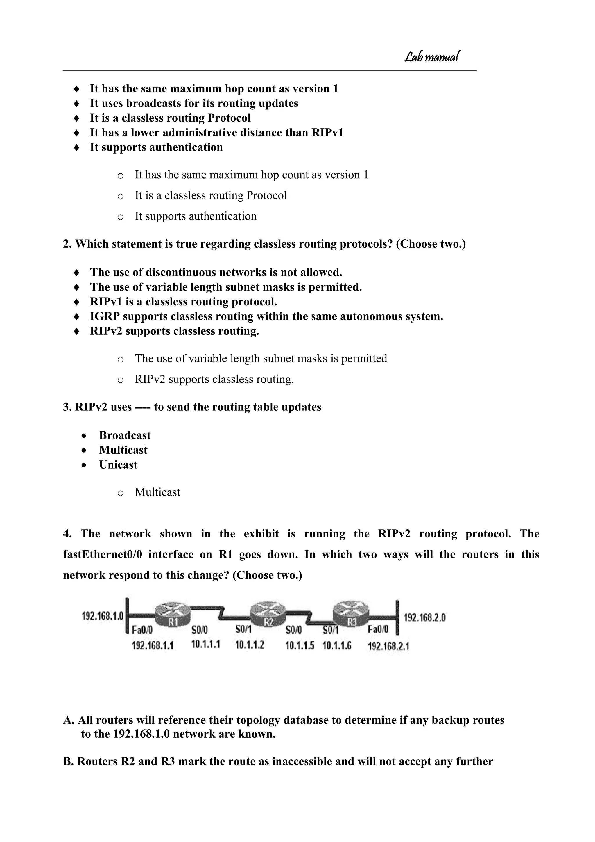
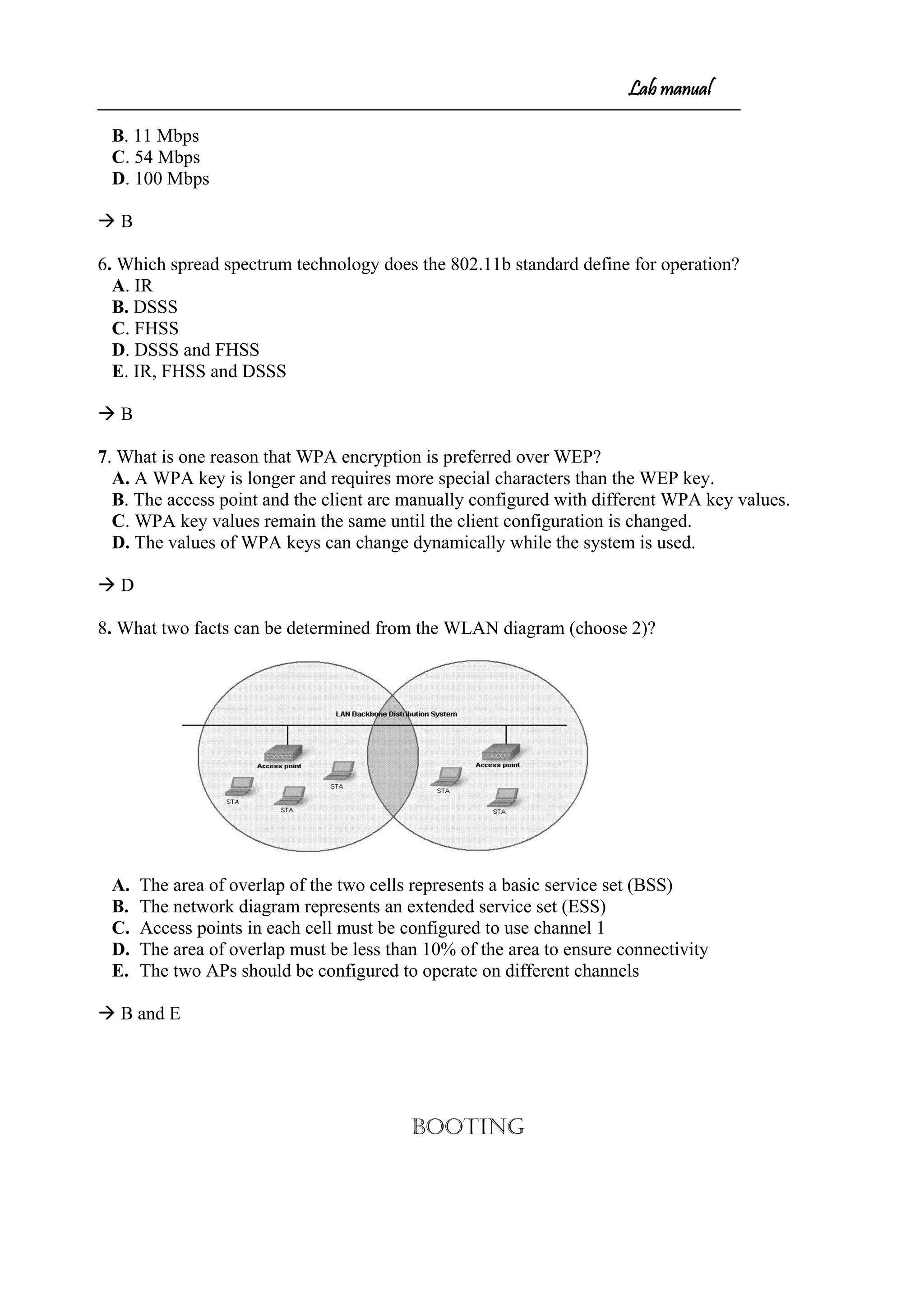
Router#sh ip route
Codes: C - connected, S - static, I - IGRP, R - RIP, M - mobile, B - BGP
D - EIGRP, EX - EIGRP external, O - OSPF, IA - OSPF inter area
N1 - OSPF NSSA external type 1, N2 - OSPF NSSA external type 2
E1 - OSPF external type 1, E2 - OSPF external type 2, E - EGP
i - IS-IS, L1 - IS-IS level-1, L2 - IS-IS level-2, * - candidate default
U - per-user static route, o - ODR
Gateway of last resort is not set
C 20.0.0.0/8 is directly connected, Serial0
C 10.0.0.0/8 is directly connected, Ethernet0
R 30.0.0.0/8 [120/1] via 20.0.0.1, 00:00:06, Serial0
E:ftp 30.0.0.10
connected to 30.0.0.10
220 mohan Microsoft FTP service <version 5.0>.
user <30.0.0.10:<none>>:anonymous
331 Anonymous access allowed, send identity <e-mail name> as password.
Password:
230 Anonymous user logged in
ftp> dir
200 PORT command successful.
150 Opening ASCII mode data connection for /bin/ls.
09-17-07 07:41PM 26 Frame.txt
09-17-07 07:41PM 9 Igrp.txt
09-17-07 07:41PM 32 Isdn.txt
09-17-07 07:40PM 10 Rip.txt
226 Transfer complete.
ftp:247 bytes received in 0.00seconds 284000.00kbytes/sec.
ftp>get frame.txt
200 PORT command successful.
226 Transfer complete.
ftp:28 bytes received in 0.00seconds 26000.00kbytes/sec.
ftp>bye](https://image.slidesharecdn.com/labmannual-140804000750-phpapp02/75/Labmannual-17-2048.jpg)
![Lab manual
Commands
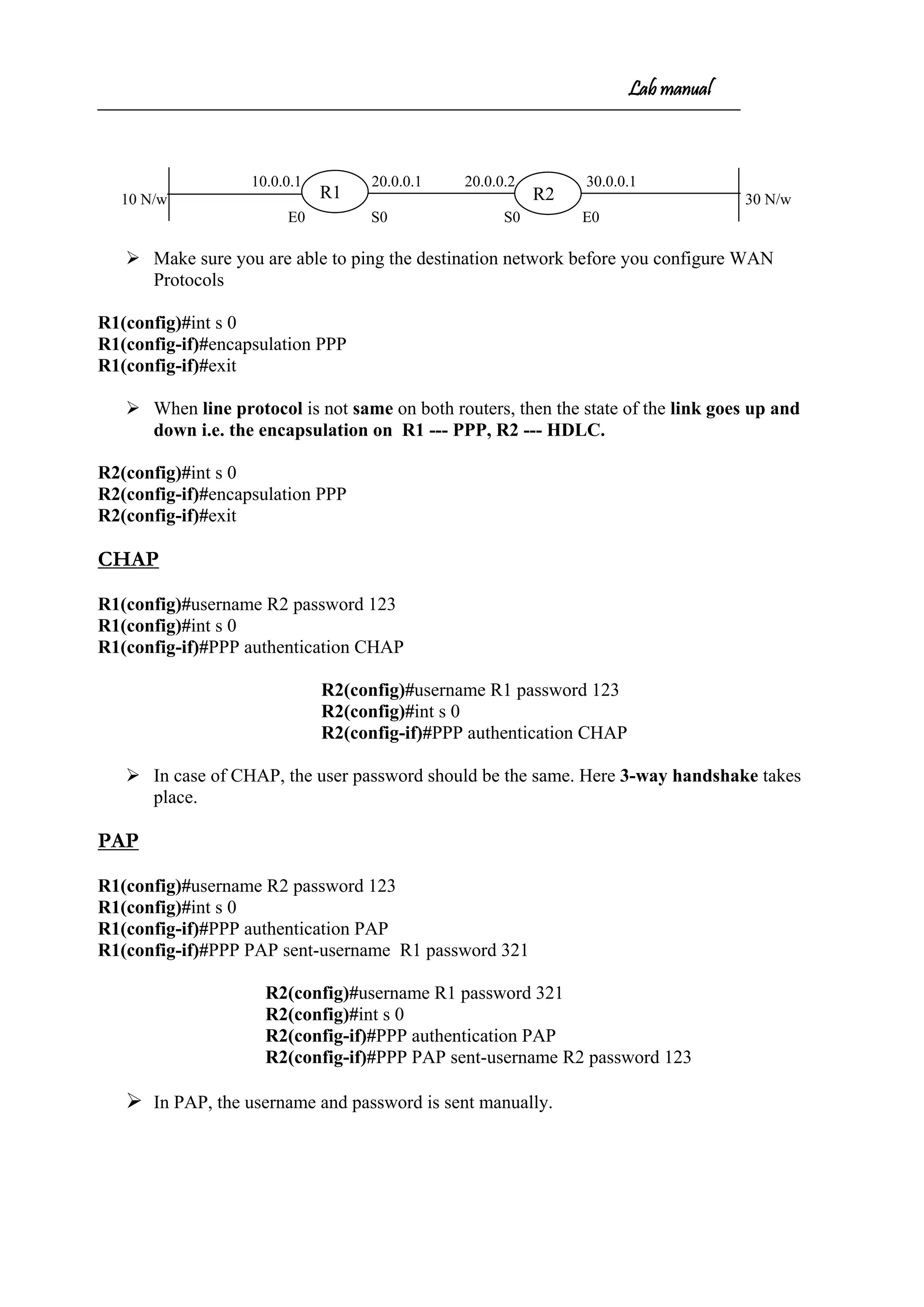
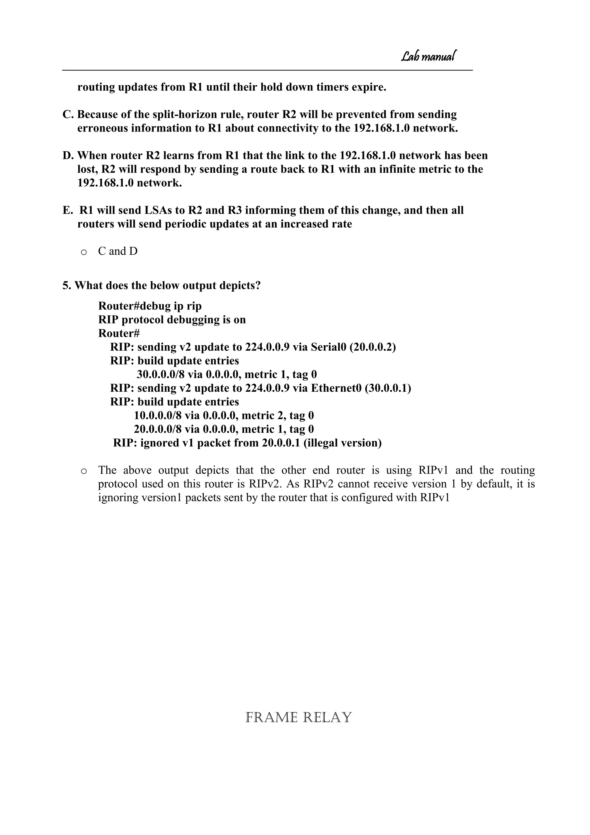
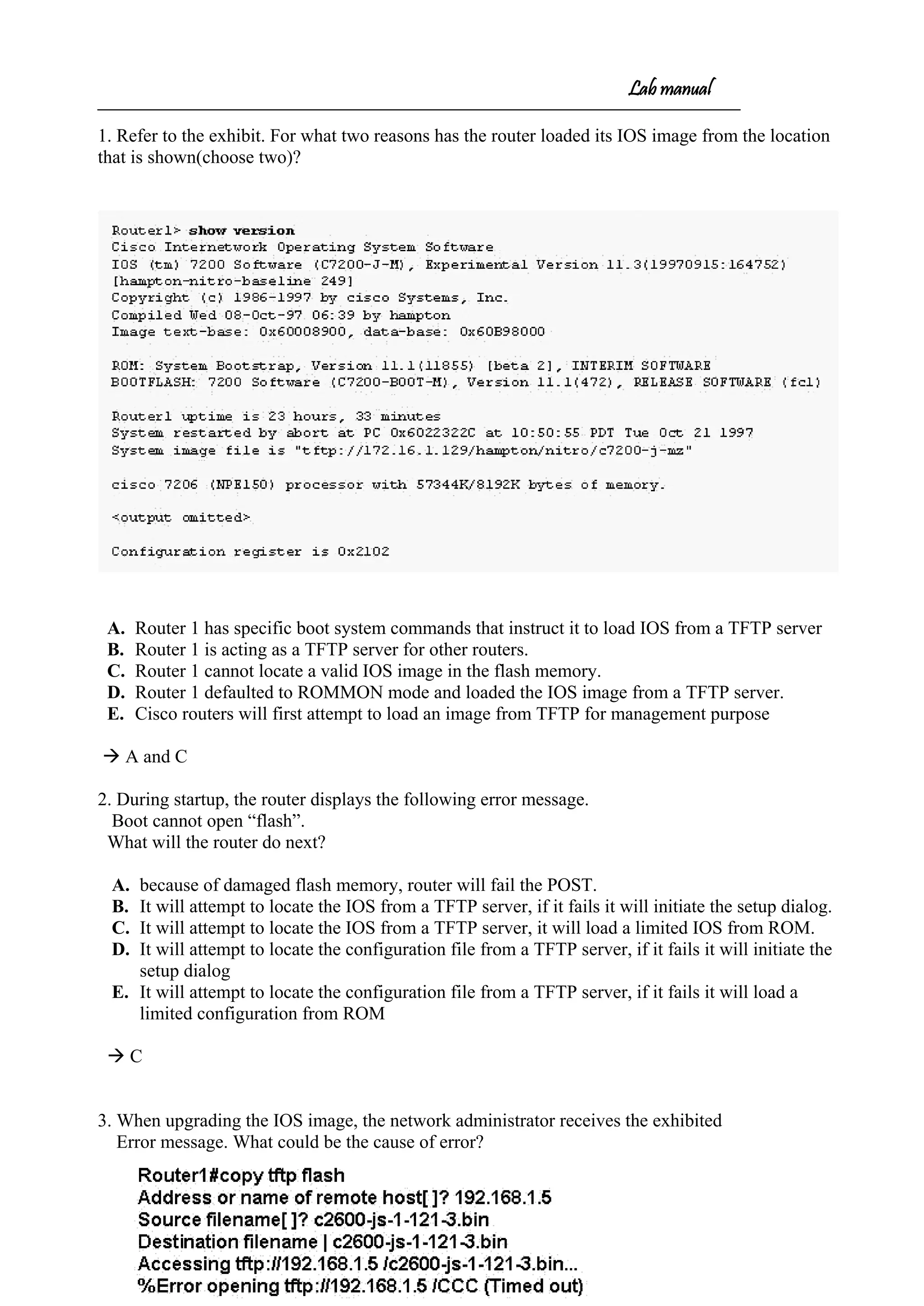
1. R1#sh sessions - To display the sessions opened by a particular user.
2. R1#(enter)(enter) - To move to the lastly opened session
3. R1#sh users - To display the users logged on
4. R1#clear line 3 - To disconnect a user
[Confirm]
R1#
5. R1#sh cdp - Works only on directly connected Cisco routers
CDP runs every 60 sec.
6. Hold time – 180 sec.
7. R1#sh cdp neighbors
R1#sh cdp neighbors
Capability Codes: R - Router, T - Trans Bridge, B - Source Route Bridge
S - Switch, H - Host, I - IGMP, r - Repeater
Device ID Local Intrfce Holdtme Capability Platform Port ID
Router Ser 0 143 R 2500 Ser 0
8. R1#show cdp neighbors detail
-------------------------
Device ID: Router
Entry address(es):
IP address: 20.0.0.2
Platform: cisco 2500, Capabilities: Router
Interface: Serial0, Port ID (outgoing port): Serial0
Holdtime : 122 sec
Version :
Cisco Internetwork Operating System Software
IOS (tm) 2500 Software (C2500-IS-L), Version 12.3(13), RELEASE SOFTWARE
(fc2)
Technical Support: http://www.cisco.com/techsupport
Copyright (c) 1986-2005 by cisco Systems, Inc.
Compiled Thu 10-Feb-05 11:49 by ssearch
advertisement version: 2
9. R1(config)#ip host <NAME> 20.0.0.2 – Creates Host Table.](https://image.slidesharecdn.com/labmannual-140804000750-phpapp02/75/Labmannual-22-2048.jpg)
![Lab manual
Security Device Manager (SDM) – GUI
Security Device Manager (SDM) is a web-based device-management tool for Cisco
routers that can simplify router deployments by allowing us to manage and troubleshoot complex
network and connectivity issues and also supports a wide range of Cisco IOS Software releases to
set up advanced configurations. It is used to configure a router through a HTTP service. To do
this make sure your router is configured with atleast one ip address on a LAN interface and
connects a host to the router.
Would you like to enter the initial configuration dialog? [yes/no]: n
Press RETURN to get started!
Router>en
Router#config t
Enter configuration commands, one per line. End with CNTL/Z.
Router(config)#int f0/0
Router(config-if)#ip address 1.1.1.1 255.255.255.0
Router(config-if)#no shut
Router(config-if)#do ping 1.1.1.2
Type escape sequence to abort.
Sending 5, 100-byte ICMP Echos to 1.1.1.2, timeout is 2 seconds:
!!!!!
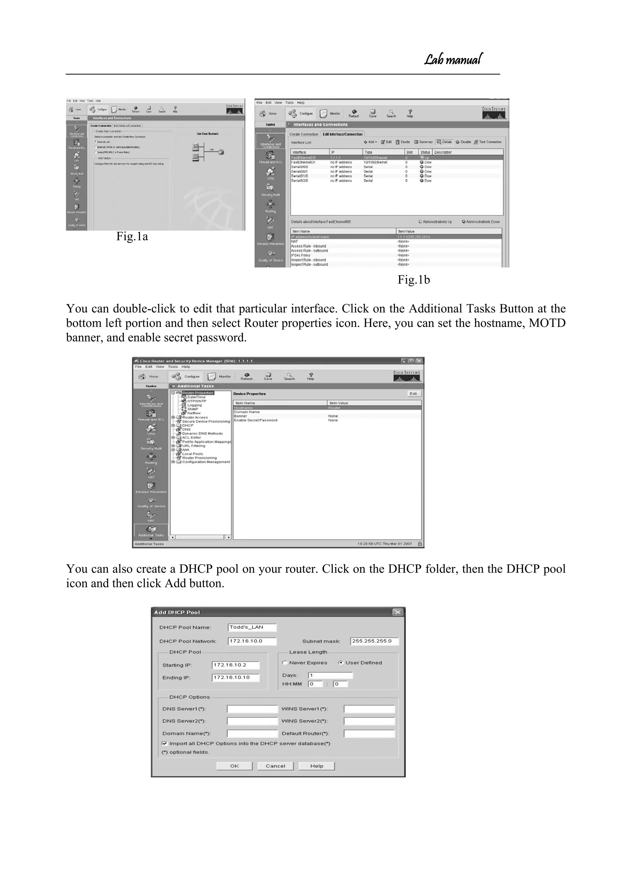
From here, you just open a browser & type http://1.1.1.1, SDM gets loaded and open a window.
Clicking the Configure button at the top of the page, choose the type of interface we want to
configure and then click the Create New Connection button at the bottom of the page (fig.1a). This
opens the LAN or WAN wizard, depending on which interface we chose to configure. By clicking
the Edit Interface/Connection tab, you get to see your interface status. (fig.1b).](https://image.slidesharecdn.com/labmannual-140804000750-phpapp02/75/Labmannual-24-2048.jpg)
![Lab manual
1. Router#debug ip nat ------------- To debug NAT
2. Router#sh ip nat translations ----------- To display translations( Displays Inside
local, Inside Global, Outside local and Outside Global )
3. R1#clear ip nat translations * ----------- To clear translations
OUTPUTS
Router#debug ip nat
IP NAT debugging is on
Router#
01:10:59: NAT*: s=10.0.0.10->20.0.0.5, d=30.0.0.1 [205]
01:10:59: NAT*: s=30.0.0.1, d=20.0.0.5->10.0.0.10 [205]
01:11:00: NAT*: s=10.0.0.10->20.0.0.5, d=30.0.0.1 [206]
01:11:00: NAT*: s=30.0.0.1, d=20.0.0.5->10.0.0.10 [206]
Router#sh ip nat translations
Pro Inside global Inside local Outside local Outside global
ICMP 20.0.0.5 10.0.0.10 --- ---
Questions](https://image.slidesharecdn.com/labmannual-140804000750-phpapp02/75/Labmannual-32-2048.jpg)
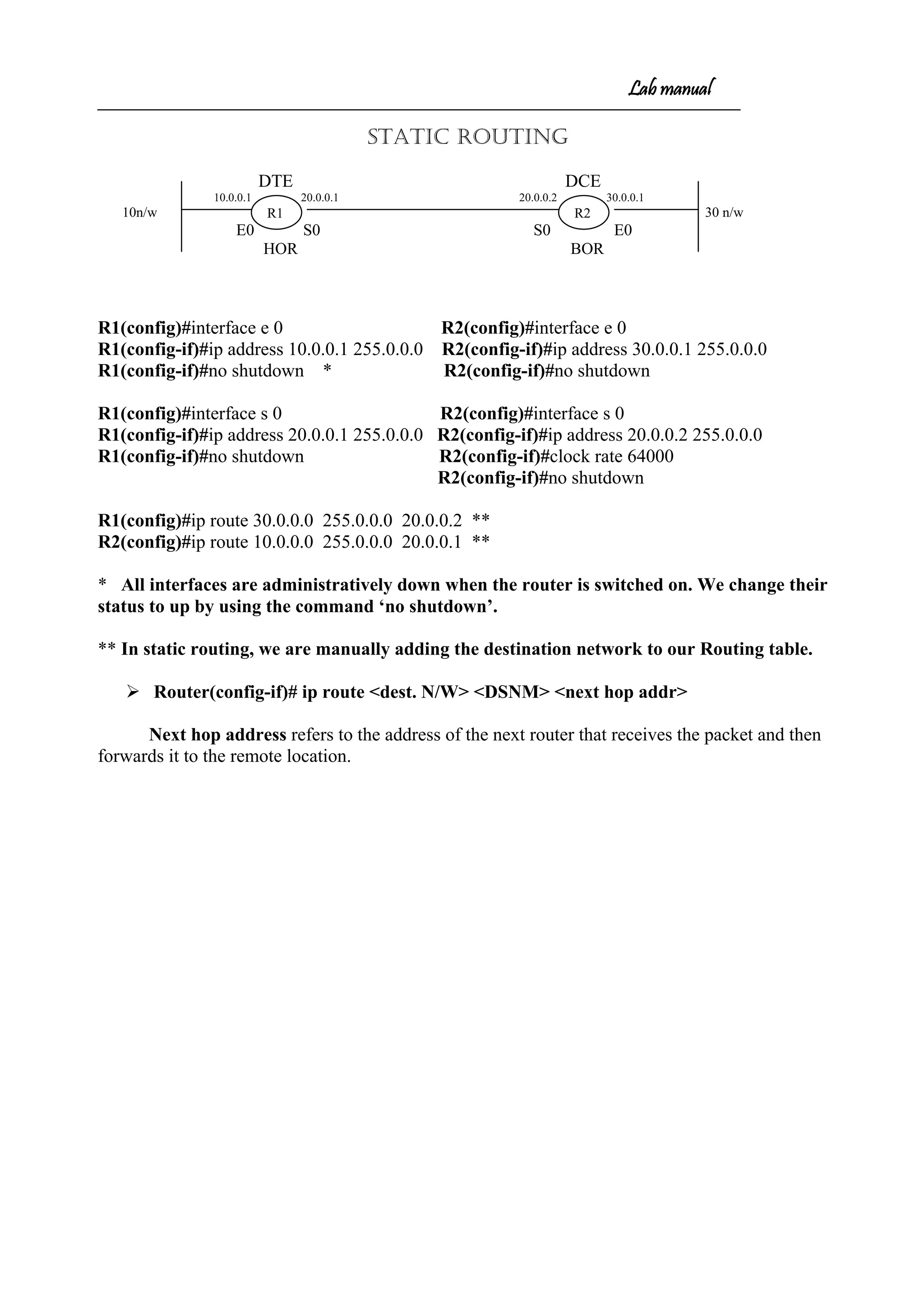
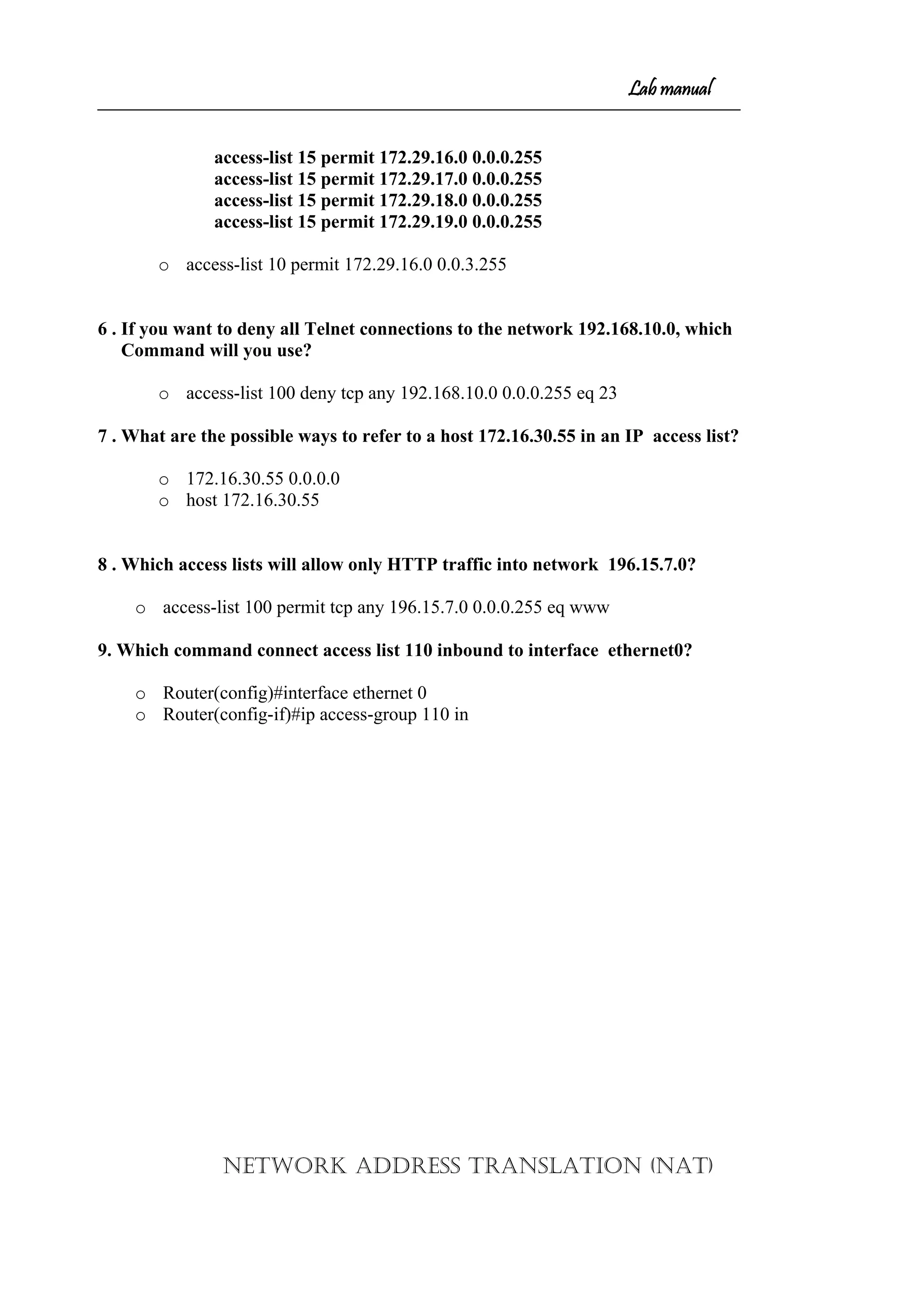
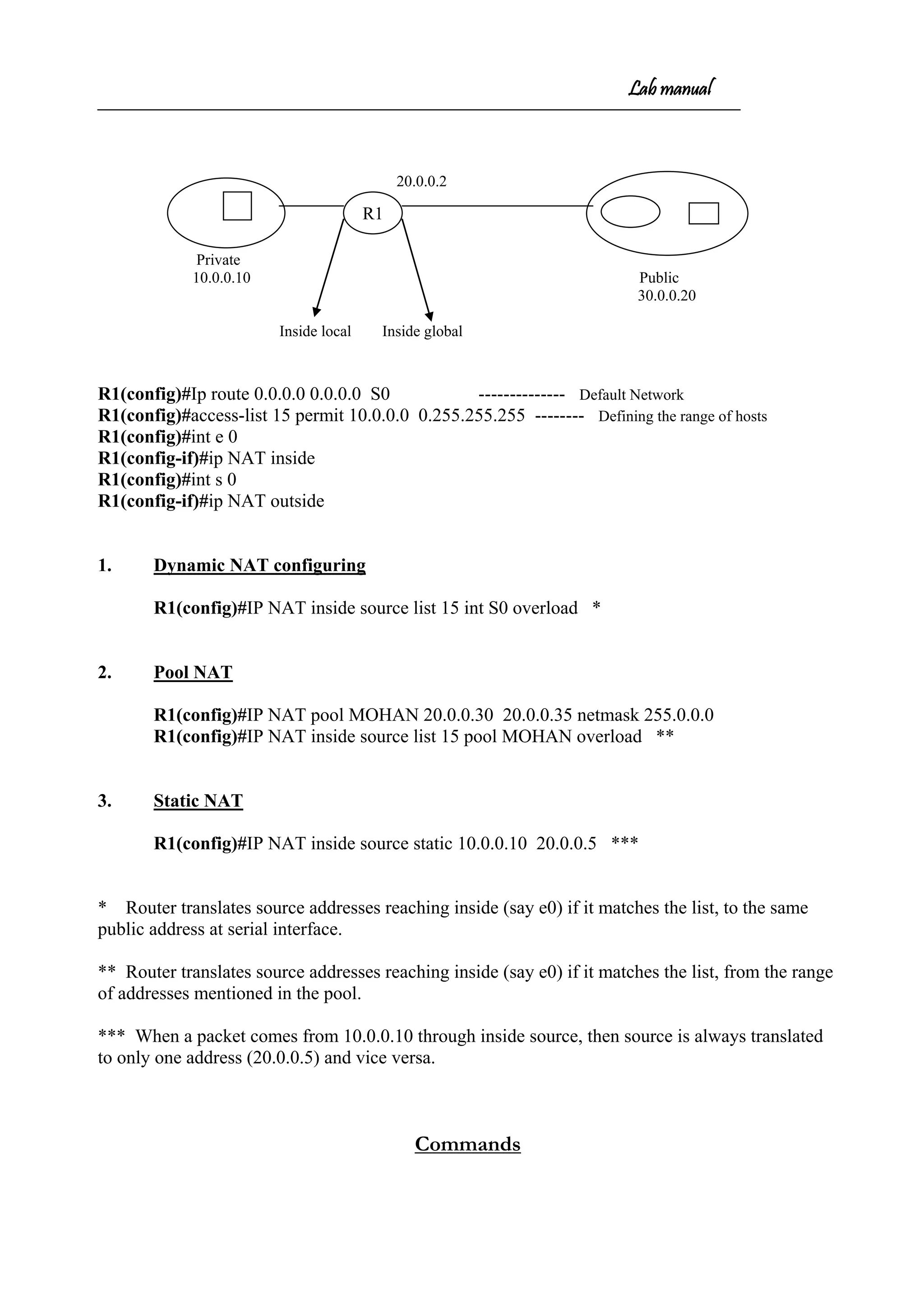
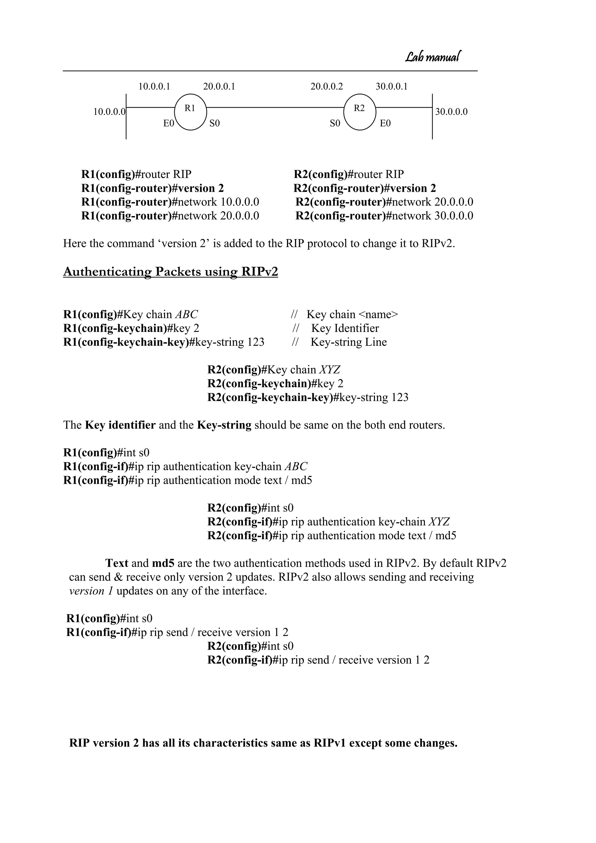
![Lab manual
10.0.0.0 10.0.0.1 20.0.0.1 20.0.0.2 30.0.0.1 30.0.0.0
OSPF
Router(config)#router OSPF <process-id> ------- [Process-id 1 to 65535]
Router(config-router)#network <NID> <WCM>area <area no>
R1(config)#router OSPF 15
R1(config-router)#network 10.0.0.0 0.255.255.255 area 0
R1(config-router)#network 20.0.0.0 0.255.255.255 area 0
R2(config)#router OSPF 12
R2(config-router)#network 30.0.0.0 0.255.255.255 area 0
R2(config-router)#network 20.0.0.0 0.255.255.255 area 0
Between two OSPF routers the process-ids need not be the same
EIGRP
R1(config)#router EIGRP <autonomous-no> ---------- [autonomous-no 1 to 65535]
R1(config-router)#network <NID>
R1(config)#router EIGRP 123
R1(config-router)#network 10.0.0.0
R1(config-router)#network 20.0.0.0
R2(config)#router EIGRP 123
R2(config-router)#network 30.0.0.0
R2(config-router)#network 20.0.0.0
The autonomous system numbers should be the same while communicating between
EIGRPs
In OSPF, area should be same.
Loop back interface
R2R1](https://image.slidesharecdn.com/labmannual-140804000750-phpapp02/75/Labmannual-35-2048.jpg)

![Lab manual
Invalid after 180 seconds, hold down 180, flushed after 240
Redistributing: rip
Default version control: send version 2, receive version 2
Interface Send Recv Triggered RIP Key-chain
Ethernet0/0 2 2
Serial0/1 2 2
Routing for Networks:
20.0.0.0
30.0.0.0
Routing Information Sources:
Gateway Distance Last Update
20.0.0.1 120 00:00:03
Distance: (default is 120)
[ By default RIPv2 can send & receive only version 2 updates ]
• Authentication modes is text on both routers
Router#debug ip rip
RIP protocol debugging is on
Router#
RIP: sending v2 update to 224.0.0.9 via Ethernet0 (30.0.0.1)
RIP: build update entries
10.0.0.0/8 via 0.0.0.0, metric 2, tag 0
20.0.0.0/8 via 0.0.0.0, metric 1, tag 0
RIP: received packet with text authentication abc
RIP: received v2 update from 20.0.0.1 on Serial0
10.0.0.0/8 via 0.0.0.0 in 1 hops
RIP: sending v2 update to 224.0.0.9 via Serial0 (20.0.0.2)
RIP: build update entries
30.0.0.0/8 via 0.0.0.0, metric 1, tag 0
• md5 is the authentication mode on both routers
Router#debug ip rip
RIP protocol debugging is on
Router#
RIP: sending v2 update to 224.0.0.9 via Serial0 (20.0.0.2)
RIP: build update entries
30.0.0.0/8 via 0.0.0.0, metric 1, tag 0
RIP: sending v2 update to 224.0.0.9 via Ethernet0 (30.0.0.1)
RIP: build update entries
10.0.0.0/8 via 0.0.0.0, metric 2, tag 0
20.0.0.0/8 via 0.0.0.0, metric 1, tag 0
RIP: received packet with MD5 authentication
RIP: received v2 update from 20.0.0.1 on Serial0
10.0.0.0/8 via 0.0.0.0 in 1 hops](https://image.slidesharecdn.com/labmannual-140804000750-phpapp02/75/Labmannual-46-2048.jpg)
![Lab manual
Trunk Port
Trunk Link
Switches
Hosts Access Link
Would you like to start initial configuration [yes/no]: no
Press return to get started
Switch>enable
Switch#configure terminal
Switch (config) #int vlan 1
* By default all ports are in the VLAN1
Switch (config-if) #ip address 10.0.0.5 255.0.0.0
Switch (config-if) #no shutdown
Switch (config-if) #exit
Switch (config) #ip default gateway 10.0.0.1
Configuring different VLANs
Switch (config) #vlan 2 // Creating the vlan
Switch (config-vlan) #name finance
Switch (config-vlan) #exit
Switch (config) #vlan 3
Switch (config-vlan) #name production
Switch (config-vlan) #exit
• [VLAN-no ranges from 2 to 1001]
• [VLAN name (xxx) is optional]
Allocating the ports to the VLANs
Switch(config)#int f 0/1
Switch(config-if)#switchport access vlan 3 // allocating ports to vlan
Switch(config-if)#exit
Switch(config)#int f 0/2
Switch(config-if)#switchport access vlan 2
Switch(config-if)#exit
Configuring the trunk Port
** Switch(config)#int f 0/24](https://image.slidesharecdn.com/labmannual-140804000750-phpapp02/75/Labmannual-59-2048.jpg)

![Lab manual
R2#sh ipv6 int brief
Ethernet0 [up/up]
FE80::210:7BFF:FE7F:B8EA
2003:ABCD:1234:1:210:7BFF:FE7F:B8EA
Serial0 [up/up]
FE80::210:7BFF:FE7F:B8EA
2005:ABCD:1234:2:210:7BFF:FE7F:B8EA
Serial1 [administratively down/down]
For each interface IPv6 will create a Link local & Global Unicast address.
Global unicast addresses
These are publicly routable addresses, and they’re the same as they are in IPv4.
Link-local addresses
These are like the private addresses in IPv4, that means they’re not routable on a public
network.
R2#sh ipv6 int e0
Ethernet0 is up, line protocol is up
IPv6 is enabled, link-local address is FE80::210:7BFF:FE7F:B8EA
Global unicast address(es):
2003:ABCD:1234:1:210:7BFF:FE7F:B8EA, subnet is 2003:ABCD:1234:1::/64
Joined group address(es):
FF02::1
FF02::2
FF02::1:FF7F:B8EA
MTU is 1500 bytes
R2#sh ipv6 int s0
Serial0 is up, line protocol is up
IPv6 is enabled, link-local address is FE80::210:7BFF:FE7F:B8EA
Global unicast address(es):
2005:ABCD:1234:2:210:7BFF:FE7F:B8EA, subnet is 2005:ABCD:1234:2::/64
Joined group address(es):
FF02::1
FF02::2
FF02::1:FF17:2
FF02::1:FF7F:B8EA
MTU is 1500 bytes
R2#sh ipv6 route ( without configuring RIP )
IPv6 Routing Table - 6 entries
Codes: C - Connected, L - Local, S - Static, R - RIP, B - BGP](https://image.slidesharecdn.com/labmannual-140804000750-phpapp02/75/Labmannual-75-2048.jpg)
![Lab manual
C 2003:ABCD:1234:1::/64 [0/0]
via ::, Ethernet0
L 2003:ABCD:1234:1:210:7BFF:FE7F:B8EA/128 [0/0]
via ::, Ethernet0
C 2005:ABCD:1234:2::/64 [0/0]
via ::, Serial0
L 2005:ABCD:1234:2:210:7BFF:FE7F:B8EA/128 [0/0]
via ::, Serial0
L FE80::/10 [0/0]
via ::, Null0
L FF00::/8 [0/0]
via ::, Null0
R2#sh ipv6 route (configuring RIP )
IPv6 Routing Table - 6 entries
Codes: C - Connected, L - Local, S - Static, R - RIP, B - BGP
U - Per-user Static route
I1 - ISIS L1, I2 - ISIS L2, IA - ISIS interarea, IS - ISIS summary
C 2003:ABCD:1234:1::/64 [0/0]
via ::, Ethernet0
L 2003:ABCD:1234:1:210:7BFF:FE7F:B8EA/128 [0/0]
via ::, Ethernet0
R 2004:abcd:1234:1::/64 [120/2]
Via FE80::200:CFF:FE91:811E, serial 0
C 2005:ABCD:1234:2::/64 [0/0]
via ::, Serial0
L 2005:ABCD:1234:2:210:7BFF:FE7F:B8EA/128 [0/0]
via ::, Serial0
L FE80::/10 [0/0]
via ::, Null0
L FF00::/8 [0/0]
via ::, Null0
R2#debug ipv6 rip
RIP Routing Protocol debugging is on
R2#
RIPng: response received from FE80::200:CFF:FE91:811E on Serial0 for 1
src=FE80::200:CFF:FE91:811E (Serial0)
dst=FF02::9 …….. Multicast address
sport=521, dport=521, length=52
command=2, version=1, mbz=0, #rte=2
tag=0, metric=1, prefix=2003:ABCD:1234:2::/64
tag=0, metric=1, prefix=2003:ABCD:1234:3::/64
RIPng: Sending multicast update on Ethernet0 for 1
src=FE80::210:7BFF:FE7F:B8EA](https://image.slidesharecdn.com/labmannual-140804000750-phpapp02/75/Labmannual-76-2048.jpg)

The serial interface is up but the line protocol is down. This indicates that while the physical layer connection is up, the data link layer is not establishing properly. Common reasons for this include: - Mismatched encapsulation types on either end (e.g. one side PPP other side HDLC) - Authentication failure if using PPP (e.g. wrong username/password) - Layer 1 issues like clock rate mismatch if using HDLC So in summary, the interface is physically up but the data link layer is failing to establish due to a configuration mismatch between the two directly connected routers.


![Vibe Coding vs. Spec-Driven Development [Free Meetup]](https://cdn.slidesharecdn.com/ss_thumbnails/vibecodingvsspecdrivendevelopment-251209105622-43f455e7-thumbnail.jpg?width=640&height=640&fit=bounds)


