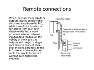
Remote connections
When thereare many inputs or
outputs located considerable
distances away from the PLC,
while it would be possible to
run cables from each such
device to the PLC a more
economic solution is to use
input/output modules in the
vicinity of the inputs and
outputs and use just a single
core cable to connect each,
over the long distances, to the
PLC instead of the multicore
cable that would be needed
without such distant I/O
modules
3.
• The cablesused for communicating data between
remote input/output modules and a central PLC,
remote PLCs and the master PLC are typically
twisted-pair cabling, often routed through
grounded steel conduit in order to reduce
electrical ‘noise’. Coaxial cable enables higher
data rates to be transmitted and does not require
the shielding of steel conduit. Fibre-optic cabling
has the advantage of resistance to noise, small
size and flexibility and is now becoming more
widely used.
4.
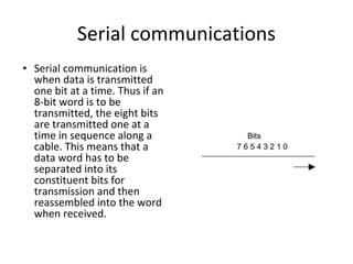
Serial communications
• Serialcommunication is
when data is transmitted
one bit at a time. Thus if an
8-bit word is to be
transmitted, the eight bits
are transmitted one at a
time in sequence along a
cable. This means that a
data word has to be
separated into its
constituent bits for
transmission and then
reassembled into the word
when received.
5.
Parallel communications
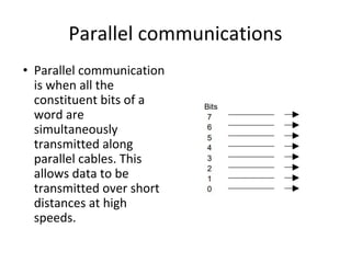
• Parallelcommunication
is when all the
constituent bits of a
word are
simultaneously
transmitted along
parallel cables. This
allows data to be
transmitted over short
distances at high
speeds.
6.
Serial Vs Parallelcommunication
Serial Communication Parallel Communication
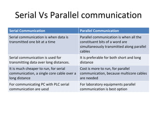
Serial communication is when data is
transmitted one bit at a time
Parallel communication is when all the
constituent bits of a word are
simultaneously transmitted along parallel
cables
Serial communication is used for
transmitting data over long distances.
It is preferable for both short and long
distance
It is much cheaper to run, for serial
communication, a single core cable over a
long distance
Cost is more to run, for parallel
communication, because multicore cables
are needed
For communicating PC with PLC serial
communication are uesd
For laboratory equipments parallel
communication is best option
7.
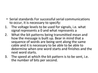
• Serial standardsFor successful serial communications
to occur, it is necessary to specify:
1. The voltage levels to be used for signals, i.e. what
signal represents a 0 and what represents a
2. What the bit patterns being transmitted mean and
how the message is built up. Bear in mind that a
sequence of words are being sent along the same
cable and it is necessary to be able to be able to
determine when one word starts and finishes and the
next word starts.
3. The speed at which the bit pattern is to be sent, i.e.
the number of bits per second.
8.
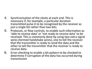
4. Synchronisation ofthe clocks at each end. This is
necessary if, for example, a particular duration
transmitted pulse it to be recognised by the receiver as
just a single bit rather than two bits.
5. Protocols, or flow controls, to enable such information as
‘able to receive data’ or ‘not ready to receive data’ to be
received. This is commonly done by using two extra signal
wires (termed handshake wires), one to tell the receiver
that the transmitter is ready to send the data and the
other to tell the transmitter that the receiver is ready to
receive data.
6. Error-checking to enable a bit pattern to be checked to
determine if corruption of the data has occurred during
transmission
9.
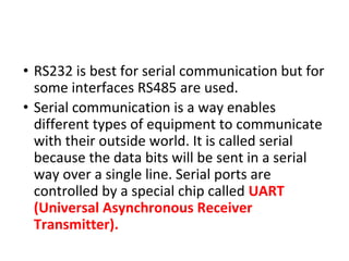
• RS232 isbest for serial communication but for
some interfaces RS485 are used.
• Serial communication is a way enables
different types of equipment to communicate
with their outside world. It is called serial
because the data bits will be sent in a serial
way over a single line. Serial ports are
controlled by a special chip called UART
(Universal Asynchronous Receiver
Transmitter).
10.
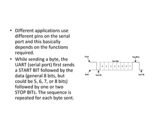
• Different applicationsuse
different pins on the serial
port and this basically
depends on the functions
required.
• While sending a byte, the
UART (serial port) first sends
a START BIT followed by the
data (general 8 bits, but
could be 5, 6, 7, or 8 bits)
followed by one or two
STOP BITs. The sequence is
repeated for each byte sent.
11.
• Serial communicationcan be half duplex or full duplex. Full
duplex communication means that a device can receive and
transmit data at the same time. Half duplex means that the
device cannot send and receive at the same time. It can do
them both, but not at the same time.
Advantages of serial communication:
• One of the advantages is transmission distance, a serial link
can send data to a remote device more far than parallel
link.
• Simple serial link cable connection
• Use less number of wire
• Serial link is used also for Infrared communication, now
many devices such as laptops & printers can communicate
via an inferred link.
12.
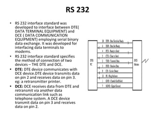
RS 232
• RS232 interface standard was
developed to interface between DTE(
DATA TERMINAL EQUIPMENT) and
DCE ( DATA COMMUNICATION
EQUIPMENT) employing serial binary
data exchange. It was developed for
interfacing data terminals to
modems.
• RS 232 interface standard specifies
the method of connection of two
devices – THE DTE and DCE.
• DTE: DTE device communicates with
DCE device.DTE device transmits data
on pin 2 and receives data on pin 3.
eg: a retransmitter printer.
• DCE: DCE receives data from DTE and
retransmit via another data
communication link such as
telephone system. A DCE device
transmit data on pin 3 and receives
data on pin 2.
13.
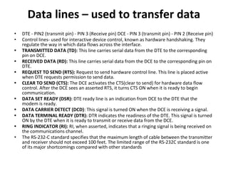
Data lines –used to transfer data
• DTE - PIN2 (transmit pin) - PIN 3 (Receive pin) DCE - PIN 3 (transmit pin) - PIN 2 (Receive pin)
• Control lines- used for interactive device control, known as hardware handshaking. They
regulate the way in which data flows across the interface.
• TRANSMITTED DATA (TD): This line carries serial data from the DTE to the corresponding
pin on DCE.
• RECEIVED DATA (RD): This line carries serial data from the DCE to the corresponding pin on
DTE.
• REQUEST TO SEND (RTS): Request to send hardware control line. This line is placed active
when DTE requests permission to send data.
• CLEAR TO SEND (CTS): The DCE activates the CTS(clear to send) for hardware data flow
control. After the DCE sees an asserted RTS, it turns CTS ON when it is ready to begin
communication.
• DATA SET READY (DSR): DTE ready line is an indication from DCE to the DTE that the
modem is ready.
• DATA CARRIER DETECT (DCD): This signal is turned ON when the DCE is receiving a signal.
• DATA TERMINAL READY (DTR): DTR indicates the readiness of the DTE. This signal is turned
ON by the DTE when it is ready to transmit or receive data from the DCE.
• RING INDICATOR (RI): RI, when asserted, indicates that a ringing signal is being received on
the communications channel.
• The RS-232-C standard specifies that the maximum length of cable between the transmitter
and receiver should not exceed 100 feet. The limited range of the RS-232C standard is one
of its major shortcomings compared with other standards
14.
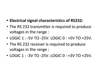
• Electrical signalcharacteristics of RS232:
• The RS 232 transmitter is required to produce
voltages in the range :
• LOGIC 1 : -5V TO -25V. LOGIC 0 : +5V TO +25V.
• The RS 232 receiver is required to produce
voltages in the range :
• LOGIC 1 : -3V TO -25V. LOGIC 0 : +3V TO +25V.
15.
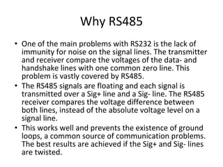
Why RS485
• Oneof the main problems with RS232 is the lack of
immunity for noise on the signal lines. The transmitter
and receiver compare the voltages of the data- and
handshake lines with one common zero line. This
problem is vastly covered by RS485.
• The RS485 signals are floating and each signal is
transmitted over a Sig+ line and a Sig- line. The RS485
receiver compares the voltage difference between
both lines, instead of the absolute voltage level on a
signal line.
• This works well and prevents the existence of ground
loops, a common source of communication problems.
The best results are achieved if the Sig+ and Sig- lines
are twisted.
17.
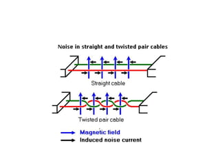
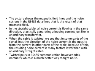
• The pictureshows the magnetic field lines and the noise
current in the RS485 data lines that is the result of that
magnetic field.
• In the straight cable, all noise current is flowing in the same
direction, practically generating a looping current just like in
an ordinary transformer.
• When the cable is twisted, we see that in some parts of the
signal lines the direction of the noise current is the oposite
from the current in other parts of the cable. Because of this,
the resulting noise current is many factors lower than with
an ordinary straight cable.
• Twisted pairs in RS485 communication however adds
immunity which is a much better way to fight noise.
18.
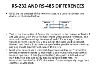
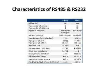
RS-232 AND RS-485DIFFERENCES
• RS-232 is the simplest of the two interfaces. It is used to connect two
devices as illustrated below:
• That is, the transmitter of Device 1 is connected to the receiver of Device 2
and vice versa. Both lines are single-ended with a ground reference. The
standard specifies a voltage between -3 and -25 V as a logic 1 and a
voltage between +3 and +25 V as a logic 0. The cable used to connect
Device 1 and Device 2 can be made up of either parallel wires or a twisted
pair and should generally not exceed 15 meters.
• Most serial devices use a Universal Asynchronous Receiver Transmitter
(UART) integrated circuits to implement a communication protocol that
transmits portions of data (typically 8 bits) along with a defined set of
start-bits, stop-bits, and parity-bits at a specified data rate. The
transmitted data is often ASCII characters. Data rates typically range from
4800 to 115.200 baud.
19.
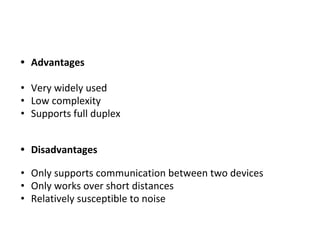
• Advantages
• Verywidely used
• Low complexity
• Supports full duplex
• Disadvantages
• Only supports communication between two devices
• Only works over short distances
• Relatively susceptible to noise
20.
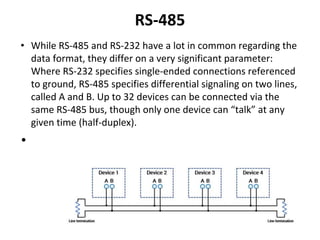
RS-485
• While RS-485and RS-232 have a lot in common regarding the
data format, they differ on a very significant parameter:
Where RS-232 specifies single-ended connections referenced
to ground, RS-485 specifies differential signaling on two lines,
called A and B. Up to 32 devices can be connected via the
same RS-485 bus, though only one device can “talk” at any
given time (half-duplex).
•
21.
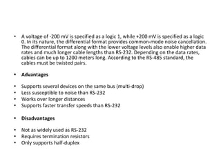
• A voltageof -200 mV is specified as a logic 1, while +200 mV is specified as a logic
0. In its nature, the differential format provides common-mode noise cancellation.
The differential format along with the lower voltage levels also enable higher data
rates and much longer cable lengths than RS-232. Depending on the data rates,
cables can be up to 1200 meters long. According to the RS-485 standard, the
cables must be twisted pairs.
• Advantages
• Supports several devices on the same bus (multi-drop)
• Less susceptible to noise than RS-232
• Works over longer distances
• Supports faster transfer speeds than RS-232
• Disadvantages
• Not as widely used as RS-232
• Requires termination resistors
• Only supports half-duplex
22.
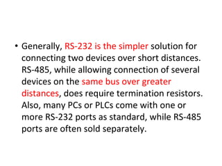
• Generally, RS-232is the simpler solution for
connecting two devices over short distances.
RS-485, while allowing connection of several
devices on the same bus over greater
distances, does require termination resistors.
Also, many PCs or PLCs come with one or
more RS-232 ports as standard, while RS-485
ports are often sold separately.
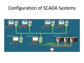
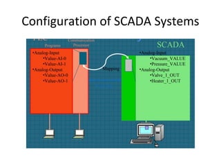
Supervisory Control &Data Acquisition
System
• used to monitor and control a plant or
equipment in industries such as:
telecommunications, water and waste control,
energy, oil and gas refining and transportation
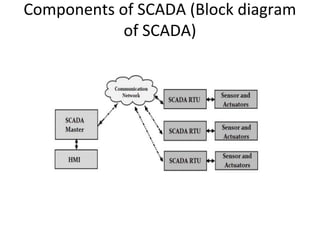
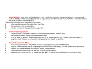
• Master StationIt is the heart of SCADA system: It has a dedicated computer in a central location. It monitors and
controls the RTUs. The master station consists of Engineering work stations, HMI (Human Machine Interface) stations
and large databases (for storing data).
The master station performs the following functions:
1. Collects and processes information from the RTUs.
2. Stores collected data on a database
3. Provides interface to the operators through HMIs
• Communication equipment
1. Communication is carried out between Master Station and Remote Terminal Units.
2. The communication is bidirectional (both to and from).
3. It can be wired or wireless. Wired communication can be through twisted pair cables or fiber optic cables or
telephone lines. Wireless communication can be using radio signals or satellites
• Remote Terminal Unit (RTUs)
1. These are special units like PLCs which are placed at geographically distributed field sites.
2. They are connected with sensors for getting various information like voltage, current, temperature or pressure.
3. They are also connected with actuators like pumps, relays or valves
4. RTUs collect information from the field and controls the field devices.
5. Sometimes they store data in a local data base and waits for instruction from Master Station to send data.
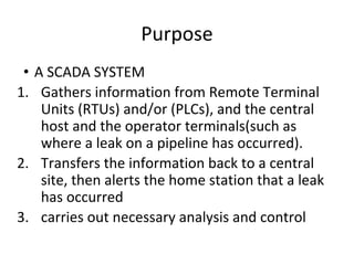
Purpose
• A SCADASYSTEM
1. Gathers information from Remote Terminal
Units (RTUs) and/or (PLCs), and the central
host and the operator terminals(such as
where a leak on a pipeline has occurred).
2. Transfers the information back to a central
site, then alerts the home station that a leak
has occurred
3. carries out necessary analysis and control
30.
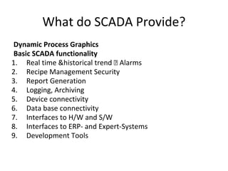
What do SCADAProvide?
Dynamic Process Graphics
Basic SCADA functionality
1. Real time &historical trend Alarms
2. Recipe Management Security
3. Report Generation
4. Logging, Archiving
5. Device connectivity
6. Data base connectivity
7. Interfaces to H/W and S/W
8. Interfaces to ERP- and Expert-Systems
9. Development Tools
31.
DEVICE CONNECTIVITY
• Everymanufacturer have there one way
communication or follow different protocols.
SCADA S/W should have connectivity to
different h/w used in automation
32.
Benefits of SCADA
1.Standard frame for application
2. Rich functionality (50 - 100 p-yrs investment)
3. Reliability and Robustness (very large
installed base, mission critical processes)
4. Limited specific development
5. Technical support and maintenance
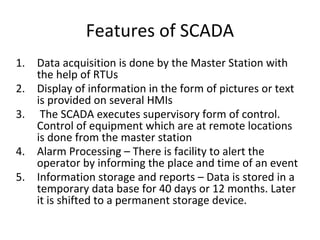
Features of SCADA
1.Data acquisition is done by the Master Station with
the help of RTUs
2. Display of information in the form of pictures or text
is provided on several HMIs
3. The SCADA executes supervisory form of control.
Control of equipment which are at remote locations
is done from the master station
4. Alarm Processing – There is facility to alert the
operator by informing the place and time of an event
5. Information storage and reports – Data is stored in a
temporary data base for 40 days or 12 months. Later
it is shifted to a permanent storage device.