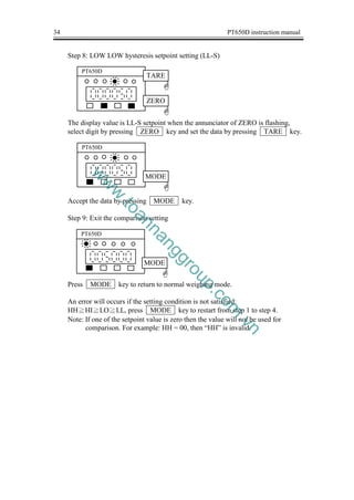
This document provides instructions for operating the PT650D weighing indicator. It describes the indicator's features, specifications, functions, calibration process, and input/output capabilities. The PT650D can interface with various load cells and accessories, displays weight measurements, and includes options for digital and analog output and setpoint control. The manual provides detailed steps for setup, operation, and troubleshooting the indicator for different weighing applications.
Dự án xây dựng nhà máy bột giấy gia lai
CÔNG TY MÔI TRƯỜNG THẢO NGUYÊN XANH
Trụ sở: 158 Nguyễn Văn Thủ, P. Đakao, Quận 1, Hồ Chí Minh
Hotline: 0839118552 - 0918755356
Fax: 08391185791
VP Hà Nội: P. 502 Số B9/D6 khu đô thị mới Cầu Giấy, Phường Dịch Vọng, Quận Cầu Giấy, Hà Nội
Hotline: ĐT: 0433526997
Home:
http://thaonguyenxanhgroup.com
http://www.lapduan.com.vn/
http://lapduandautu.com.vn/
http://lapduan.net
Trong xu thế hội nhập sâu rộng vào nền kinh tế thế giới hiện nay, chiến lược
đúng đắn có vai trò quyết định trong sự phát triển và lớn mạnh của doanh nghiệp. Với
những nỗ lực phát triển bền bỉ và ổn định, không ngừng nâng cao chất lượng, đa dạng
hóa sản phẩm thỏa mãn sự mong đợi của người tiêu dùng, hiện tại – Bia Sài
Gòn đang chiếm giữ vị trí dẫn đầu trong ngành Bia VN và 5 lần liên tục vinh dự được
công nhận là Thương hiệu Quốc Gia. Bia Sài Gòn cũng đã tự hào trở thành thành
viên thứ 351 tại Học viện Bia Berlin – một trong những cái nôi của văn hóa bia toàn
cầu.
Năm 2016, Sabeco chính thức niêm yết cổ phiếu trên sàn giao dịch chứng
khoán TP.HCM, trở thành Công ty có vốn hóa thị trường hàng đầu tại Việt Nam. Việc
công khai, minh bạch cũng được xem là “cú hích” quan trọng thúc đẩy sự thay đổi, thể
hiện qua việc giá cổ phiếu Sabeco tăng trưởng vượt bậc, lọt vào nhóm những cổ phiếu
có giá trị cao nhất trên thị trường chứng khoán và gia tăng đáng kể giá trị cho cổ đông,
nhà đầu tư.
https://tailieu.tv/
Phương pháp nghiên cứu và thực hiện luận văn thạc sĩ Đại học kinh tế quốc dân...Nguyễn Thị Thanh Tươi
IẾT LUẬN VĂN THẠC SĨ KINH TẾ
Chúng tôi chuyên nhận làm trọn gói Dịch vụ viết thuê luận văn thạc sỹ kinh tế uy tín – chất lượng của ngành kinh tế. Với sự chuyên nghiệp và trợ giúp của các giảng viên thạc sĩ, tốt nghiệp MBA loại giỏi tại các trường đại học, chúng tôi tin tưởng rằng có thể giúp các bạn đang gặp khó khăn trong việc viết luận văn thạc sỹ kinh tế.
Các chuyên ngành hỗ trợ
Kinh tế bất động sản
Kế hoạch đầu tư
Luật kinh tế, luật dân dự,..
Chứng khoán
Tài chính ngân hàng
Kế toán, kiểm toán
Bảo hiểm
Thương mại
Quan hệ quốc tế
Quản trị nhân lực
Marketting
Tư vấn trực tiếp: Miss Mai 0988.377.480
Email: dvluanvankt@gmail.com
Dự án tốt nghiệp Dự án phát triển nghề trồng nấmYenPhuong16
Dự án phát triển nghề trồng nấm, Dự án tốt nghiệp phát triển nghề trồng nấm, Xây dựng nhà trồng nấm, Công nghệ trồng nấm Rơm, Công nghệ trồng nấm Linh Chi,
Dịch vụ lập báo cáo môi trường ĐTM | Xử lý nước thải | 0903034381
Thiết kế quy hoạch
Lập báo cáo môi trường
Lập dự án
Xử lý nước thải
http://lapduandautu.com.vn
How can Trung Nguyen, one of the most reputable coffee company in Vietnam, penetrate the USA market? The project explores the potential of the brand introduction in the USA by researching on the market, the culture, the trend, suggesting the strategies and tactics for market acquisition with a sub-brand of organic coffee, producing the sample deliverables (sub-brand name, logo, packaging, promotion video).
Tiểu luận về công ty TH true milk, 9 điểm. Nhà quản trị điều hành chịu trách nhiệm xây dựng một hệ thống chuyển đổi hiệu quả. Nhà quản trị điều hành sẽ phát huy khả năng của mình bằng việc hỗ trợ công ty thông qua vi ệc sử dụng một cách kinh tế các nguôn lực. Nhà quản trị điều hành quản lý hàng loạt các hệ thống trong chức năng quản trị sản xuất và điều hành. Hệ thống quản trị sản xuất và điều hành đa dạng bao gồm hệ hống hoạnh định tồn kho, hệ thống mua hàng, hệ thống bảo trì. Các nhà quản trị sản xuất điều hành còn phải đảm nhiệm một loạt các hệ thống nằm ngoài chức năng quản trị sản xuất điều hành. Một số hệ thống này là những bộ phận của công ty chẳng hạn như hệ thống marketing, hệ thống tài chính. Một số hệ thống bên ngoài khác bên ngoài công ty như các hệ thông kinh tế, hệ thống thương mai quốc tế và hệ thống chính trị. Nhà quản trị giỏi là nha quản trị hiểu được các hệ tống bên trong và bên ngoài công ty.
Xã hội phát triển, đời sống người dân được nâng cao về mọi mặt. Sức khỏe là một trong những vấn đề được quan tâm và được đặt lên hàng đầu. Để đáp ứng được nhu cầu về bảo vệ và chăm sóc sức khỏe cho người dân, nhiệm vụ của ngành Dược Việt Nam là phải không ngừng nghiên cứu phát triển đưa ra nhiều loại thuốc mới có hiệu quả điều trị cao. Để đưa thuốc vào sử dụng rộng rãi trong xã hội, phải cần đến những nhà máy xí nghiệp sản xuất Dược Phẩm đạt yêu cầu về sản xuất thuốc tốt, để đảm bảo được chất lượng thuốc. Trong số các nhà máy, xí nghiệp hiện nay thì Công Ty CPDP Phong Phú là một nhà máy tiêu biểu và có thể đáp ứng được những yêu cầu mà xã hội ngày nay mong muốn để góp phần cải thiện, nâng cao sức khỏe của cộng đồng. Công Ty CPDP Phong Phú là một công ty có quy mô sản xuất lớn, chính vì vậy mà ban lãnh đạo Trường cao đẳng Đại Việt Sài Gòn đã phối hợp với Công Ty CPDP Phong Phú để tạo điều kiện cho tập thể sinh viên được đến thực tập tại Công Ty Cổ Phần Dược Phẩm Phong Phú
Dịch vụ lập báo cáo môi trường ĐTM | Xử lý nước thải | 0918755356
Thiết kế quy hoạch
Lập báo cáo môi trường
Lập dự án
Xử lý nước thải
http://lapduandautu.com.vn
Tiểu luận về công ty nước giải khát coca-cola [Mới]. Ngày nay, với sự phát triển mạnh mẽ của nền kinh tế thị trường, cạnh tranh trở lên gay gắt, do đó sự phân cực cũng diễn ra nhanh chóng, quyết liệt hơn. Trong cuộc đọ sức đó, những doanh nghiệp hoạch định được cho mình một chiến lược kinh doanh, tạo cái khung hướng dẫn tư duy hành động, hướng tới thực hiện những mục tiêu cụ thể mà công ty đã đặt ra, thì mới có thể tồn tại và phát triển trên thị trường.
Hoạch định chiến lược marketing sản phẩm naturenz của công ty tot pharma. Hoạch định chiến lược Marketing sản phẩm Naturenz của Công ty TNHH MTV TOT Pharma, từ đó đề xuất cách thức tổ chức thực hiện chiến lược Marketing cho Công ty để đáp ứng tốt nhu cầu của khách hàng.
Nhận viết luận văn Đại học , thạc sĩ - Zalo: 0917.193.864
Tham khảo bảng giá dịch vụ viết bài tại: vietbaocaothuctap.net
Download luận văn đồ án tốt nghiệp ngành điện công nghiệp với đề tài: Xây dựng, thiết kế hệ thống cân định lượng và đóng bao tự động, cho các bạn làm luận văn tham khảo
www.envimart.vn - ĐT: 028 77727979 - sales@envimart.vn - Nền tảng cung cấp thiết bị, vật tư ngành nước và môi trường. Chuyên cung cấp vật tư cho dự án xử lý nước sạch, nước thải và môi trường. Envimart luôn đồng hành, tin cậy với đối tác nhà thầu, nhà tích hợp và người sử dụng.
GMT-H2 is a wall/desk-mount weighing transmitter with stainless steel shell which reaches IP65 protection. 2-inch LED display with 6 digits and indicator lights. It can be widely used in the industrial automation fields, such as silo weighing, platform weighing, weight checking, loss-in-weight, liquid filling, batching, and so on.
www.envimart.vn - ĐT: 028 77727979 - sales@envimart.vn - Nền tảng cung cấp thiết bị, vật tư ngành nước và môi trường. Chuyên cung cấp vật tư cho dự án xử lý nước sạch, nước thải và môi trường. Envimart luôn đồng hành, tin cậy với đối tác nhà thầu, nhà tích hợp và người sử dụng.
Digital Weighing Transmitter with RS232/485 and analogue outputGeneral Measure
GM7702, a digital weighing transmitter with the standard dimension, is suitable for mounting on DIN rail in many industrial fields. Small size and flat compact design make it ideally integrate with whole weighing sector. Due to its high practicability, stability and easy operation, GM7702 can be widely applied to the industry of feeds, chemical, concrete and bitumen mixing, metallurgy smelting, etc..
www.envimart.vn - ĐT: 028 77727979 - sales@envimart.vn - Nền tảng cung cấp thiết bị, vật tư ngành nước và môi trường. Chuyên cung cấp vật tư cho dự án xử lý nước sạch, nước thải và môi trường. Envimart luôn đồng hành, tin cậy với đối tác nhà thầu, nhà tích hợp và người sử dụng.
GM8802S-T weighing indicators are specially designed for weighing industrial fields, which have features of small volume, plenty of communicating commands, stable performance, easy operation, and practicability.
www.envimart.vn - ĐT: 028 77727979 - sales@envimart.vn - Nền tảng cung cấp thiết bị, vật tư ngành nước và môi trường. Chuyên cung cấp vật tư cho dự án xử lý nước sạch, nước thải và môi trường. Envimart luôn đồng hành, tin cậy với đối tác nhà thầu, nhà tích hợp và người sử dụng.
Find out more about Infineon on our Homepage: www.infineon.com
Infineon offers a comprehensive portfolio of LED Drivers for general lighting applications, such as indoor and outdoor lighting, architectural lighting and channel letters. Find here all information about LED Driver "BCR402U" from Infineon Technologies: Features, Applications and General Description.
Sachpazis:Terzaghi Bearing Capacity Estimation in simple terms with Calculati...Dr.Costas Sachpazis
Terzaghi's soil bearing capacity theory, developed by Karl Terzaghi, is a fundamental principle in geotechnical engineering used to determine the bearing capacity of shallow foundations. This theory provides a method to calculate the ultimate bearing capacity of soil, which is the maximum load per unit area that the soil can support without undergoing shear failure. The Calculation HTML Code included.
Using recycled concrete aggregates (RCA) for pavements is crucial to achieving sustainability. Implementing RCA for new pavement can minimize carbon footprint, conserve natural resources, reduce harmful emissions, and lower life cycle costs. Compared to natural aggregate (NA), RCA pavement has fewer comprehensive studies and sustainability assessments.
Overview of the fundamental roles in Hydropower generation and the components involved in wider Electrical Engineering.
This paper presents the design and construction of hydroelectric dams from the hydrologist’s survey of the valley before construction, all aspects and involved disciplines, fluid dynamics, structural engineering, generation and mains frequency regulation to the very transmission of power through the network in the United Kingdom.
Author: Robbie Edward Sayers
Collaborators and co editors: Charlie Sims and Connor Healey.
(C) 2024 Robbie E. Sayers
Final project report on grocery store management system..pdfKamal Acharya
In today’s fast-changing business environment, it’s extremely important to be able to respond to client needs in the most effective and timely manner. If your customers wish to see your business online and have instant access to your products or services.
Online Grocery Store is an e-commerce website, which retails various grocery products. This project allows viewing various products available enables registered users to purchase desired products instantly using Paytm, UPI payment processor (Instant Pay) and also can place order by using Cash on Delivery (Pay Later) option. This project provides an easy access to Administrators and Managers to view orders placed using Pay Later and Instant Pay options.
In order to develop an e-commerce website, a number of Technologies must be studied and understood. These include multi-tiered architecture, server and client-side scripting techniques, implementation technologies, programming language (such as PHP, HTML, CSS, JavaScript) and MySQL relational databases. This is a project with the objective to develop a basic website where a consumer is provided with a shopping cart website and also to know about the technologies used to develop such a website.
This document will discuss each of the underlying technologies to create and implement an e- commerce website.
Immunizing Image Classifiers Against Localized Adversary Attacksgerogepatton
This paper addresses the vulnerability of deep learning models, particularly convolutional neural networks
(CNN)s, to adversarial attacks and presents a proactive training technique designed to counter them. We
introduce a novel volumization algorithm, which transforms 2D images into 3D volumetric representations.
When combined with 3D convolution and deep curriculum learning optimization (CLO), itsignificantly improves
the immunity of models against localized universal attacks by up to 40%. We evaluate our proposed approach
using contemporary CNN architectures and the modified Canadian Institute for Advanced Research (CIFAR-10
and CIFAR-100) and ImageNet Large Scale Visual Recognition Challenge (ILSVRC12) datasets, showcasing
accuracy improvements over previous techniques. The results indicate that the combination of the volumetric
input and curriculum learning holds significant promise for mitigating adversarial attacks without necessitating
adversary training.
Hybrid optimization of pumped hydro system and solar- Engr. Abdul-Azeez.pdffxintegritypublishin
Advancements in technology unveil a myriad of electrical and electronic breakthroughs geared towards efficiently harnessing limited resources to meet human energy demands. The optimization of hybrid solar PV panels and pumped hydro energy supply systems plays a pivotal role in utilizing natural resources effectively. This initiative not only benefits humanity but also fosters environmental sustainability. The study investigated the design optimization of these hybrid systems, focusing on understanding solar radiation patterns, identifying geographical influences on solar radiation, formulating a mathematical model for system optimization, and determining the optimal configuration of PV panels and pumped hydro storage. Through a comparative analysis approach and eight weeks of data collection, the study addressed key research questions related to solar radiation patterns and optimal system design. The findings highlighted regions with heightened solar radiation levels, showcasing substantial potential for power generation and emphasizing the system's efficiency. Optimizing system design significantly boosted power generation, promoted renewable energy utilization, and enhanced energy storage capacity. The study underscored the benefits of optimizing hybrid solar PV panels and pumped hydro energy supply systems for sustainable energy usage. Optimizing the design of solar PV panels and pumped hydro energy supply systems as examined across diverse climatic conditions in a developing country, not only enhances power generation but also improves the integration of renewable energy sources and boosts energy storage capacities, particularly beneficial for less economically prosperous regions. Additionally, the study provides valuable insights for advancing energy research in economically viable areas. Recommendations included conducting site-specific assessments, utilizing advanced modeling tools, implementing regular maintenance protocols, and enhancing communication among system components.
Cosmetic shop management system project report.pdfKamal Acharya
Buying new cosmetic products is difficult. It can even be scary for those who have sensitive skin and are prone to skin trouble. The information needed to alleviate this problem is on the back of each product, but it's thought to interpret those ingredient lists unless you have a background in chemistry.
Instead of buying and hoping for the best, we can use data science to help us predict which products may be good fits for us. It includes various function programs to do the above mentioned tasks.
Data file handling has been effectively used in the program.
The automated cosmetic shop management system should deal with the automation of general workflow and administration process of the shop. The main processes of the system focus on customer's request where the system is able to search the most appropriate products and deliver it to the customers. It should help the employees to quickly identify the list of cosmetic product that have reached the minimum quantity and also keep a track of expired date for each cosmetic product. It should help the employees to find the rack number in which the product is placed.It is also Faster and more efficient way.
5. PT650D instruction manual 1
1. DESCRIPTION
1-1 INTRODUCTION
PT650D is a kind of general weighing indicator, employing the latest technology
for the reliable and best performance quality assurance, cost effective design
which includes many functions. PT650D is suitable for all kinds of application
such as hopper and weigh platform.
1-2 DEFINITION
Multiplier:
The multiplier determine the position of the decimal point or the number of tailing
zero added to the internal reading.
For example:
If the internal reading is 234,
Multiplier Display on indicator
10 2340
1 234
.1 23.4
.01 2.34
.001 .234
.0001 .0234
Division:
The ratio of step width to multiplier. The value of division can only be one of the
followings: 1, 2, 5.
Step width:
The difference between two consecutive reading of the scale.
Excitation voltage:
The voltage that supplied by the indicator to the load cell.
Load cell:
Load cell is a device that converts force to electronic voltage. A load cell consists
of two parts. The first part is a sensor that can be linear distorted according to the
force applied to it. The second part is the strain gauge element which changes its
resistance according to the distortion of the sensor.
w
w
w
.
t
o
a
n
n
a
n
g
g
r
o
u
p
.
c
o
m
.
v
n
6. 2 PT650D instruction manual
Load cell rated output:
The output voltage from the load cell divided by the excitation voltage.
Maximum capacity:
The maximum figure ignoring decimal point that designed to be used by the
indicator.
Resolution:
The ratio of the maximum capacity and division.
Dead weight:
The output voltage of the load cell in response to the weight of the platform.
Span:
The change of reading from the indicator in response to the change of standard
weight applied.
1-3 FEATURES
- Apply for all strain gauge load cell;
- Clear and stable 13mm 6 digitals LED display;
- gross weight and net weight can be selected;
- Display step width is selectable of 1, 2, 5, 10, 20 or 50;
- Numeric display “O.L.” when overload;
- Display decimal point is selectable of 4 decimal places;
- Automatic zero tracking;
- Automatically set tare by push button;
- Delta-sigma conversion method;
- Internal resolution is 16,000,000 counts;
- Scale display resolution from 300 to 10,000;
- Conversion rate up to 200 times/sec;
- Software function setting method;
- External on/off switch for function and calibration setting protection;
- Option:
RS232/RS485 input and output port;
Hi/Lo comparator output (opto-couple, dielectric strength 80VDC,
300mA);
Parallel BCD output;
or Analog output;
- Optional software: single material batching control software.
w
w
w
.
t
o
a
n
n
a
n
g
g
r
o
u
p
.
c
o
m
.
v
n
7. PT650D instruction manual 3
2. SPECIFICATION
2-1 GENERAL
1. Mains supply : 110VAC, 220VAC±10%, 50/60Hz
2. Power consumption : 9 VA
3. Operating temperature : -5℃ to 50℃(23℉ to 122℉)
4. Relative Humidity : 90%(non-condensing)
5. Weight : Approx 0.45 kg
2-2 DIGITAL SECTION
1. Weight display : 6 digits LED display
2. Display height : 13mm
3. Annunciators : Gross, Net, Zero, Motion and unit(kg/t)
4. Negative sign indication : “-” on the left most digit
5. Over-range indication : Display “O.L”
6. Maximum capacity : 500 to 100,000
7. Step width : 1, 2, 5, 10, 20 or 50
8. Decimal point : Displays to four different decimal places
2-3 ANALOG SECTION
1. Load cell type : All strain gauge load cell
2. Load cell supply : 10VDC±5%, 150mA
3. Output sensitivity : 0.5μV/D to 200μV/D
4. Input resistance : More than 100MΩ at 500VDC between each
terminal
5. Zero point adjustment : 0.05mV to 15mV
6. Span stability : ±
8ppm/ K of F.S
7. Zero stability : ±
(0.4μV±
0.006% initial zero offset
voltage)/K
8. Non-linearity : Within 0.005% of F.S
9. Conversion method : Delta-sigma
10. Conversion rate : Up to 200 times/sec
11. Internal resolution : 16,000,000
12. Maximum display resolution : 10,000 divisions
13. Comparison cycle : Approx 200 times/sec
w
w
w
.
t
o
a
n
n
a
n
g
g
r
o
u
p
.
c
o
m
.
v
n
8. 4 PT650D instruction manual
14. Dielectric strength : Between input terminal(common/earth/each
opto-coupler output/analog output/BCD
output), for 1 min, at 500VDC.
Between power supply terminal and input
terminal(common/earth/each opto-coupler
output/analog output/BCD output), for 1 min,
at 1500VAC.
OPTION:
15. Analog or BCD output : 0~5V, 0~20mA/4~20mA(selectable),
parallel BCD
16. Serial output : RS232 or RS485 option
17. Control output : Four opto-coupler option
2-4 RS232/RS485 SERIAL OUTPUT (OPTION)
1) STANDARD : EIA-RS232/RS485 output
2) STREAM FROMAT
Data bit = 7
Parity bit = 1 (even)
Stop bit = 1
Code = ASCII code
Baud rate = 2400, 4800, 9600, 19200
Delimiter = CR/LF
3) RS232/RS485 MODE
a) Command mode: After receiving the command word from
RS232/RS485 port, the indicator will carry out
the appropriate action, those command valid
only for RS232/RS485 port.
Command: READ<CR><LF> : request measured data
TARE<CR><LF> : request TARE weight setting
KEY<CR><LF> : key protection ON or OFF
ZERO<CR><LF> : request ZERO value
Example: Read command (READ<CR><LF>) is
“52H, 45H, 41H, 44H, 0DH, 0AH” in ASCII code.
b) Continuous mode: The data will be transferred constantly without any
input command to the RS232/RS485 port.
w
w
w
.
t
o
a
n
n
a
n
g
g
r
o
u
p
.
c
o
m
.
v
n
9. PT650D instruction manual 5
4) DATA FORMAT:
STATUS 1 STATUS 2 WEIGHING DATA UNIT
STATUS 1:
OL = overload
ST = stable
US = unstable
STATUS 2:
NT = net weight
GS = gross weight
WEIGHING DATA:
An eight bits stream consists of "0" to "9", negative
sign "-", positive sign "+", space " " and decimal
point.
UNIT:
kg = kilogram
t = ton
5) SCHEMATIC DIGRAM FOR THE OUTPUT PORT
, LF
CR
,
RS232 output
TXD (+)
RXD (-)
COM
TXD
RXD
RS232 RS485
RS485 output
RS485 RS232
+ (TXD)
- (RXD)
+
-
PT650D
(1)
PT650D
(2)
w
w
w
.
t
o
a
n
n
a
n
g
g
r
o
u
p
.
c
o
m
.
v
n
10. 6 PT650D instruction manual
+
-
+
-
+
-
+
-
+
-
+
-
( ID 01)
( ID 03)
( ID 02)
( ID 04)
( ID XX)
6) RS485 COMMUNICATION
Note: ID = XX, ST62(TERMINATER)on the mainboard should be set to “ON”,
a 200Ù impedance matching resistor is virtually added to communication
terminal.
2-5 Hi/Lo COMPARATOR OUTPUT(OPTION)
1) Hi/Lo output : HH, Hi, Lo or LL
2) Max. capacity : 80VDC, 300mA
2-6 BCD OUTPUT(OPTION)
1) BCD output : Parallel BCD output
2) BCD output level : TTL or open collector
2-7 ANALOG OUTPUT(OPTION)
1) Analog output mode : 0~5V/0~20mA/4~20mA
2) The excitation current will be reduced to 120mA if the 0~20mA/4~20mA
output board is used.
2-8 INPUT(BUILT-IN)
1) Input : IN1, IN2 or IN3
2) Input mode : Passive switch
3) Input contact time : 30 ms
PC PT650D
PT650D
PT650D
PT650D
PT650D
w
w
w
.
t
o
a
n
n
a
n
g
g
r
o
u
p
.
c
o
m
.
v
n
11. PT650D instruction manual 7
3. OPERATION
3-1 GENERAL RULES
Do not install the PT650D in direct sunshine, and avoid sudden temperature
changes, vibration or wind.
Best performance is achieved when temperature is about 20℃or 68℉and the
relative humidity is about 50%.
Ground the PT650D via the power cable to the rear terminal and ensure a good
ground connection. Do not ground directly to other equipment.
Analog input/output signals are sensitive to electrical noise. Do not bind these
cables together as it could result in cross-talk interference. Please also keep them
well away from AC power cable, and keep all cable as short as possible.
If the local AC electrical supply fluctuates by more than±10% an AC regulator
must be used in order to stabilize the power and reduce power spikes.
3-2 INPUT SENSITIVITY OF LOAD CELL
The input sensitivity (A) of load cell can be calculated from the following
formula:
A = (Load cell output voltage at scale capacity - load cell output voltage at dead
load) × Step width / Scale capacity
PT650D requires that “A” must be greater than or equal to 0.5μV/D.
w
w
w
.
t
o
a
n
n
a
n
g
g
r
o
u
p
.
c
o
m
.
v
n
12. 8 PT650D instruction manual
3-3 CONNECTING THE LOAD CELL TO THE INDICATOR
The analog output from the Load cell and the RS232/RS485 input/output signals
are sensitive to electrical noise. Do not bind these cables together as it could result
in cross-talk interference. Please also keep them well away from the AC power
cables.
Load cell connections
Pin no. Signal
EXC+
EXC-
SIG+
SIG-
SHD
Excitation+
Excitation -
Signal +
Signal -
Shield
SIG- SIG+
EXC-
EXC+
SHD
SHD
EXC-
EXC+
SIG-
SIG+
w
w
w
.
t
o
a
n
n
a
n
g
g
r
o
u
p
.
c
o
m
.
v
n
13. PT650D instruction manual 9
4. INDICATOR AND KEYS
4-1 INDICATOR
Function mode : Display “FUNC” by pressing MODE and G/N keys
for 2 seconds to enter the function mode
Calibration mode : Display “CAL” by pressing MODE and TARE keys
for 2 seconds to enter the calibration mode
Hi/Lo setpoint mode: Display “SET” by pressing MODE and ZERO keys
for 2 seconds to enter the Hi/Lo setpoint mode
Indicator On/Off : Press MODE key for 3 seconds
kg/lb conversion : Press G/N key for 2 seconds, unit is 1b while “kg”
annunciator is flashing, and press G/N key for 2 seconds,
unit is kg.
(Note: 1kg = 2.2046 lb)
Note: For the setting modes, press and hold MODE key first, otherwise, no
entry is accepted. When changing the entry before its completion, press
MODE key to input again.
4-2 FRONT PANEL DESCRIPTION
1. key: Entry the data or skips the span at calibration.
2. key: Selects set data items or changes the gross/net value display
or skips the zero at calibration.
3. key: Shifts the setting digit at the time of data setting or change
the display mode to net mode.
4. key: Select the setting digit at the time of data setting or if the
zero offset is within 1% to 10% of maximum capacity, press
this key to return to zero.
5. annunciator: Indicates gross weight is displayed
6. annunciator: Indicates net weight is displayed
7. annunciator: Indicates motion detection
8. annunciator: Indicates gross value is “0”
9. annunciator: Indicates unit is “kg”
10. annunciator: Indicates unit is “ton”
Note: The decimal point in the setting digit will be blink at the time of data
setting. The data entry can not be a negative value.
PT650D
○GROSS ○NET ○MOTION ○ZERO ○kg ○t
MODE g TARE ▲ G/N ■ ZERO4
MODE
G/N
TARE
ZERO
GROSS
NET
MOTION
ZERO
kg
t
w
w
w
.
t
o
a
n
n
a
n
g
g
r
o
u
p
.
c
o
m
.
v
n
14. 10 PT650D instruction manual
HH
(OP)
HI
(PL)
LO
(FF)
LL(ZB)
EMTR
COM
IN2
IN3
TXD1
RXD1
COM
+
COM
SIG+
SIG-
EXC+
EXC-
SHIELD
IN1
COM
EARTH
AC
AC
4-3 REAR PANEL DESCRIPTION
1. Mains power input terminal: AC, AC, EARTH
2. Load cell input terminal: SIG+, SIG-, EXC+, EXC-, SHIELD
3. Input terminal: IN1, IN2, IN3,COM
4. Hi/Lo comparison output terminal: HH, HI, LO, LL, EMTR COM
Single material batch output terminal: OP, PL, FF, ZB, EMTR COM
5. Serial communicate terminal: TXD1, RXD1, COM
6. Analog signal output terminal: +, COM
w
w
w
.
t
o
a
n
n
a
n
g
g
r
o
u
p
.
c
o
m
.
v
n
15. PT650D instruction manual 11
5. FUNCTION SETTING
Enter function setting: Press and hold MODE key, then press G/N key, 2
seconds later, displays “FUNC”, the function setting mode is selected, and set the
data within “F0 0” to “F19 XX”.
If the data is changed, enter the calibration mode.
Keys description:
key : Select the function No. (from F0 to F19 to F0).
key : Change the data value(from FX 0 to 1,2… … .).
Note: (1) Data setting by RS232/RS485 is possible.
(2) If an error occurs, “ERROR X” will output from RS232/RS485.
(3) When a “check sum” error occurs or there is the function change of
“max.cap”, “mult” or “step”, PT650D is set to the “CAL” re-set
mode(the message is automatically displayed). However, if the
power supply is turn on/off under that state, it will enter the
weighing mode.
(4) Percentage of zero range can be ignored.
5-1 DATA SETTING
Enter the data setting:
Press and hold MODE key, then press G/N key, 2 seconds later, displays
“FUNC”.
2 seconds later
2 seconds later
PT650D
G
MODE
G
G
G/N
PT650D
ZERO
TARE
PT650D
w
w
w
.
t
o
a
n
n
a
n
g
g
r
o
u
p
.
c
o
m
.
v
n
16. 12 PT650D instruction manual
5-1-1 "F0 0" EXIT THE FUNCTION SETTING MODE
Press MODE key, accept the data, and enter the weighing mode, if press
ZERO key, skip to the next setting.
5-1-2 "F1 0" ZERO TRACK TIME
Press TARE key to select 0 = No track
1 = 1 sec
5-1-3 "F2 0" ZERO TRACK BAND
Press TARE key to select 0 = 1 step width
1 = 2 step width
2 = 4 step width
5-1-4 "F3 0" MOTION DETECTION
Press TARE key to select 0 = 1 step width/sec
1 = 3 step width/sec
2 = 5 step width/sec
3 = 10 step width/sec
PT650D
G
ZERO
PT650D
PT650D
G
ZERO
G
ZERO
PT650D
G
ZERO
w
w
w
.
t
o
a
n
n
a
n
g
g
r
o
u
p
.
c
o
m
.
v
n
17. PT650D instruction manual 13
5-1-5 "F4 0" MULTIPLIER OR DECIMAL POINT
Press TARE key to select 0 = 10
1 = 1
2 = 0.1
3 = 0.01
4 = 0.001
5 = 0.0001
5-1-6 "F5 0" DIVISION
Press TARE key to select 0 = 1
1 = 2
2 = 5
5-1-7 "F6 0" MAXIMUM CAPACITY
Press TARE key to select 0 = 500 8 = 5000 16 = 30000
1 = 1000 9 = 6000 17 = 40000
2 = 1200 10 = 8000 18 = 50000
3 = 1500 11 = 10000 19 = 60000
4 = 2000 12 = 12000 20 = 80000
5 = 2500 13 = 15000 21 = 100000
6 = 3000 14 = 20000
7 = 4000 15 = 25000
If the maximum capacity does not satisfy the following condition, it will show
“ERROR 1” for 2 seconds, return to the F4 (decimal point) setting mode.
Maximum capacity ≧ 500
Maximum capacity ≦ 100,000
Note: “ERROR 1” is also output to RS232/RS485.
PT650D
G
ZERO
PT650D
G
ZERO
PT650D
G
ZERO
w
w
w
.
t
o
a
n
n
a
n
g
g
r
o
u
p
.
c
o
m
.
v
n
18. 14 PT650D instruction manual
5-1-8 "F7 0" BAUD RATE
Press TARE key to select 0 = 2400 baud
1 = 4800 baud
2 = 9600 baud
3 = 19200 baud
5-1-9 "F8 0" RS232/RS485 OUTPUT MODE
Press TARE key to select 0 = Continuous mode
1 = Command mode
5-1-10 "F9 0" UNIT
Press TARE key to select 0 = kg
1 = ton
5-1-11 "F10 0" ZERO RETURN RANGE
Press TARE key to select 0 = 1% 5 = 6%
1 = 2% 6 = 7%
2 = 3% 7 = 8%
3 = 4% 8 = 9%
4 = 5% 9 = 10%
Note: At the normal weighing mode, the zero return range is within 1% to 10% of
maximum capacity by pressing ZERO key.
PT650D
G
ZERO
PT650D
G
ZERO
PT650D
G
ZERO
PT650D
G
ZERO
w
w
w
.
t
o
a
n
n
a
n
g
g
r
o
u
p
.
c
o
m
.
v
n
19. PT650D instruction manual 15
5-1-12 "F11 0" DIGITAL FILTER
Press TARE key to select 0 = 0 5 = 32
1 = 2 6 = 64
2 = 4 7 = 128
3 = 8 8 = 256
4 = 16 9 = 512
5-1-13 "F12 0" DISPLAY UPDATE RATE
Press TARE key to select 0 = 1 time/sec
1 = 4 times/sec
2 = 8 times/sec
3 = 16 times/sec
4 = 20 times/sec
5-1-14 "F13 0" BCD OUTPUT RATE
Press TARE key to select 0 = 4 times/sec
1 = 8 times/sec
2 = 16 times/sec
3 = 20 times/sec
4 = 60 times/sec
5 = 80 times/sec
6 = 100 times/sec
7 = 200 times/sec
Note: No need to set without BCD board.
5-1-15 "F14 0" RS485 ID CODE
Press TARE key to select 00 ~ 99
Note: This parameter will be activated only for RS485 option.
The ID code must not be the same as the other PT650D which connected
to the same master device.
ID = 00, only single device communication.
PT650D
G
ZERO
PT650D
G
ZERO
0 More sensible
512 Less sensible
PT650D
G
ZERO
PT650D
G
ZERO
w
w
w
.
t
o
a
n
n
a
n
g
g
r
o
u
p
.
c
o
m
.
v
n
20. 16 PT650D instruction manual
5-1-16 "F15 0" PEAK HOLD
Press TARE key to select 0 = Peak hold is not valid
1 = Peak hold(automatically)
2 = Valley hold(automatically)
3 = Peak – valley hold(automatically)
4 = Peak hold(external)
5 = Valley hold(external)
6 = Peak – valley hold(external)
Note: 4, 5 or 6 must be matched to “8 = Peak hold” of F16, F17 or F18.
5-1-17 "F16 0" INPUT 1
Press TARE key to select 0 = Function
1 = Zero
2 = Tare
3 = Gross/Net
4 = Print
5 = kg/lb
6 = On/Off
7 = Hold
8 = Peak hold
5-1-18 "F17 0" INPUT 2
Press TARE key to select 0 = Function
1 = Zero
2 = Tare
3 = Gross/Net
4 = Print
5 = kg/lb
6 = On/Off
7 = Hold
8 = Peak hold
5-1-19 "F18 0" INPUT 3
Press TARE key to select 0 = Function
1 = Zero
2 = Tare
3 = Gross/Net
4 = Print
5 = kg/lb
6 = On/Off
7 = Hold
8 = Peak hold
PT650D
G
ZERO
PT650D
G
ZERO
PT650D
G
ZERO
PT650D
G
ZERO
w
w
w
.
t
o
a
n
n
a
n
g
g
r
o
u
p
.
c
o
m
.
v
n
21. PT650D instruction manual 17
5-1-20 "F19 0" COMPARISON CONDITION
Press TARE key to select 0 = Gross weight
1 = Net weight
2 = Display weight
Note: Comparison output according to F19 setting.
5-2 FUNCTION SETTING BY RS232/RS485 (only for RS232 or
RS485 option is installed)
Function setting can be activated by using RS232/RS485. At normal weighing
mode, from RS232 port, input a command “FUNC<CR><LF>”, the gross display
will show “FUNC”.
From RS485 port, input a command “<ENQ>IDXX<CR><LF>”, indicator
responds “<ACK>XX<CR><LF>”, then input a command “FUNC<CR><LF>”,
the gross display will show “FUNC”.
Command input PT650D responds
<ENQ>IDXX<CR><LF> (RS485) <ACK>XX<CR><LF> (RS485)
FUNC<CR><LF>
5-2-1 ZERO TRACK TIME
Z.TRACK T=0<CR><LF>
Input 0 or 1, 0 = no zero track, 1 = 1 sec
1<CR><LF> Z.TRACK T=1<CR><LF>
Input N for next setting
N<CR><LF>
5-2-2 ZERO TRACK BAND
Z.TRACK D=1<CR><LF>
Input 1, 2 or 4 step width
2<CR><LF> Z.TRACK D=2<CR><LF>
Input N for next setting
N<CR><LF>
PT650D
PT650D
G
ZERO
w
w
w
.
t
o
a
n
n
a
n
g
g
r
o
u
p
.
c
o
m
.
v
n
22. 18 PT650D instruction manual
5-2-3 MOTION DETECTION
MOTION 1D/S<CR><LF>
Input 1, 3, 5 or 10 step width
3<CR><LF> MOTION 3D/S<CR><LF>
Input N for next setting
N<CR><LF>
5-2-4 DECIMAL POINT
D.P 4<CR><LF>
Input 0, 1, 2, 3 or 4
0 = no decimal
1 = XXXX.X
2 = XXX.XX
3 = XX.XXX
4 = X.XXXX D.P 0<CR><LF>
Input N for next setting
N<CR><LF>
5-2-5 MULTIPLIER (It is possible to modify the multiplier only when no decimal
point is set)
MULT 1<CR><LF>
Input 1 or 10
10<CR><LF> MULT 10<CR><LF>
Input N for next setting
N<CR><LF>
5-2-6 DIVISION
d 1<CR><LF>
Input 1, 2 or 5
5<CR><LF> d 5<CR><LF>
Input N for next setting
N<CR><LF>
5-2-7 MAXIMUM CAPACITY
MAX.CAP 500<CR><LF>
Input one of the 22 selection of maximum capacity between 500 to 100,000
3500<CR><LF> NO ? <CR><LF>
100000<CR><LF> MAX.CAP 100000<CR><LF>
Input N for next setting
N<CR><LF>
If there is any error in the maximum capacity, step width and multiplier, error
message “ERROR 1” will be sent out, PT650D will return to 5-2-4.
w
w
w
.
t
o
a
n
n
a
n
g
g
r
o
u
p
.
c
o
m
.
v
n
23. PT650D instruction manual 19
5-2-8 RS232/RS485 BAUD RATE
BAUD 2400<CR><LF>
Input 2400, 4800, 9600 or 19200
9600<CR><LF> BAUD 9600<CR><LF>
Input N for next setting
N<CR><LF>
5-2-9 UNIT
UNIT kg<CR><LF>
Input kg or t, kg = kg, t = ton
t<CR><LF> UNIT t<CR><LF>
kg<CR><LF> UNIT kg<CR><LF>
Input N for next setting
N<CR><LF>
5-2-10 ZERO RETURN RANGE
Z.RANGE 1<CR><LF>
Input 1 to 10
3<CR><LF> Z.RANGE 3<CR><LF>
Input N for next setting
N<CR><LF>
5-2-11 DIGITAL FILTER
D.FILTER 0<CR><LF>
Input one of the 10 selection of digital filtering between 0 to 512
4<CR><LF> D.FILTER 4<CR><LF>
Input N for next setting
N<CR><LF>
5-2-12 DISPLAY UPDATE RATE
DSP RATE 1<CR><LF>
Input 1, 4, 8, 16 and 20 times/sec
4<CR><LF> DSP RATE 4<CR><LF>
Input N for next setting
N<CR><LF>
5-2-13 BCD OUTPUT RATE
BCD RATE 4<CR><LF>
Input 4, 8, 16, 20, 60, 80, 100 and 200 times/sec
8<CR><LF> BCD RATE 8<CR><LF>
Input N for next setting
N<CR><LF>
5-2-14 ID CODE
ID. NO. 00<CR><LF>
Input 00 to 99
01<CR><LF> ID. NO. 01<CR><LF>
Input N for next setting
N<CR><LF>
w
w
w
.
t
o
a
n
n
a
n
g
g
r
o
u
p
.
c
o
m
.
v
n
24. 20 PT650D instruction manual
5-2-15 PEAK HOLD
PEAK HOLD OFF<CR><LF>
Input OFF, PEAK AUTO, VALLEY AUTO,
PEAK VALLEY AUTO, PEAK EXT,
VALLEY EXT and PEAK VALLEY EXT
PEAK AUTO<CR><LF> PEAK AUTO<CR><LF>
Input N for next setting
N<CR><LF>
5-2-16 INPUT 1
INPUT1 FUNC<CR><LF>
Input FUNC, ZERO, TARE, G/N, PRINT, kg/lb,
ON/OFF, HOLD and PEAK HOLD
FUNC<CR><LF> INPUT1 FUNC<CR><LF>
Input N for next setting
N<CR><LF>
5-2-17 INPUT 2
INPUT2 PEAK HOLD<CR><LF>
Input FUNC, ZERO, TARE, G/N, PRINT, kg/lb,
ON/OFF, HOLD and PEAK HOLD
kg/1b<CR><LF> INPUT2 kg/lb<CR><LF>
Input N for next setting
N<CR><LF>
5-2-18 INPUT 3
INPUT3 PRINT<CR><LF>
Input FUNC, ZERO, TARE, G/N, PRINT, kg/lb,
ON/OFF, HOLD and PEAK HOLD
HOLD<CR><LF> INPUT3 HOLD<CR><LF>
Input N for next setting
N<CR><LF>
5-2-19 COMPARISON CONDITION
COMPARISON GROSS<CR><LF>
Input GROSS, NET and DISPLAY
DISPLAY<CR><LF> COMPARISON DISPLAY<CR><LF>
Input R to return to normal weighing mode
R<CR><LF> YES<CR><LF>
Note: When maximum capacity, division or multiplier is changed, system
must be calibrated again and reset the Hi/Lo setpoint, the display
of PT650D will show “CAL1”.
w
w
w
.
t
o
a
n
n
a
n
g
g
r
o
u
p
.
c
o
m
.
v
n
25. PT650D instruction manual 21
6. CALIBRATION
* Zero tracking can not be performed at calibration.
* The weighing data can be accepted only when motion is not detected
in calibration.
* When an error occurs, error message will output from RS232/RS485.
6-1 DURING SPAN SETTING
1. Span setting when step width and multiplier are set.
STEP WIDTH
0 1 2 3 4 5 6 7 8 9 ← 10
0
At "2" 0 2 4 6 8 ←Actual value
At "5" 0 5 ←Actual value
Also applied to 101
digit at a step width of 10, 20 or 50.
2. When multiplier is set to × 10, no 100
digit can be set.
3. When multiplier, maximum capacity or step width is changed or check sum
error occurs, the setting can not quit by pressing the MODE key(data must be
reset).
6-2 SETTING STEPS
6-2-1 CALIBRATION 1(by using standard weight)
Press and hold MODE key, then press TARE key, 2 seconds later,
display "CAL 1", and enter the calibration 1.
2 seconds later, enter the calibration 1
Press ZERO key, display as follows, and enter the zero calibration.
PT650D
PT650D
PT650D
G
MODE
G
G
TARE
w
w
w
.
t
o
a
n
n
a
n
g
g
r
o
u
p
.
c
o
m
.
v
n
26. 22 PT650D instruction manual
1. ZERO CALIBRATION
Zero calibration 1 (according to the last zero)
If there is not necessary to calibrate the zero offset, press ZERO key and
G/N key to skip the zero calibration procedure, and enter the next setting.
Zero calibration 2 (calibrate the new zero)
Calibrate zero offset, press the ZERO key and MODE key to accept the
tare value equals to 0.
2. SPAN CALIBRATION
Span calibration 1 (according to the last span)
After performing the zero calibration without error, the indicator will display
“ . ”. Press MODE key to return to normal weighing condition if
only zero adjustment is required.
Span calibration 2 (calibrate the new span)
PT650D
PT650D
G
G/N
PT650D
G
MODE
G
ZERO
PT650D
G
TARE
G
MODE
w
w
w
.
t
o
a
n
n
a
n
g
g
r
o
u
p
.
c
o
m
.
v
n
27. PT650D instruction manual 23
Put the standard weight which equals to the scale capacity to the weighing
platform, use the ZERO key and the TARE key to set the reading of the
indicator exactly the same as the value of the standard weight, press MODE
key to perform the calibration.
Note: The minimum weight required is 100 division.
6-2-2 CALIBRATION 2 (data input)
Press and hold MODE key, then press TARE key, 2 seconds later,
display "CAL 1", then press TARE key , display "CAL 2", and enter the
calibration 2.
2 seconds later,
Press TARE key, displays "CAL 2", and enter the calibration 2.
Press ZERO key, and enter the zero calibration.
PT650D
G
MODE
PT650D
PT650D
G
MODE
G
G
TARE
PT650D
PT650D
w
w
w
.
t
o
a
n
n
a
n
g
g
r
o
u
p
.
c
o
m
.
v
n
28. 24 PT650D instruction manual
1. ZERO CALIBRATION
Zero calibration 1(according to the last zero)
If there is not necessary to calibrate the zero offset, press ZERO and
G/N keys to skip the zero calibration procedure, enter the next setting.
Zero calibration 2(calibrate the new zero)
Calibrate zero offset, press the ZERO and MODE keys to accept the
tare value equals to 0.
2. SPAN CALIBRATION
Voltage setting
After performing the zero calibration without error, the indicator will display
" ", input the value(unit: mV/V)of (max. capacity – voltage value at
zero)by ZERO and TARE keys when “gross” annunciator is flashing.
Example: Zero = 0.1001mV/V
Max. capacity = 1.9998 mV/V
Input = 1.8997 mV/V.
PT650D
G
G/N
PT650D
G
MODE
PT650D
G
ZERO
G
TARE
w
w
w
.
t
o
a
n
n
a
n
g
g
r
o
u
p
.
c
o
m
.
v
n
29. PT650D instruction manual 25
Span calibration
Press G/N key to enter span calibration, or press MODE key to return to
normal weighing mode.
Press ZERO and TARE keys to enter span value when “gross”
annunicator is lit steady, and press MODE key to perform span calibration.
Note: The minimum weight required is 100 division.
6-3 ERROR CODE DURING CALIBRATION
ERROR 1 : Incorrect setting for multiplier, division, or maximum capacity.
ERROR 2 : Incorrect wiring between load cell and indicator, voltage for zero
value is greater than the voltage for span value.
ERROR 3 : Input voltage too low.
The dead weight of the weighing platform may be too light.
Add a 1% metal film resistor of 50KΩ to 500KΩbetween EX+ and
SG+.
ERROR 4 : Input voltage too high
The dead weight of the weighing platform may be too heavy.
Add a 1% metal film resistor of 50KΩ to 500KΩ between
EX + and SG-.
ERROR 5 : Input sensitivity of load cell is out of range.
ERROR 6 : Load cell output voltage at scale capacity is too high.
ERROR 7 : Zero offset is greater than zero return range.
PT650D
G
ZERO
G
TARE
PT650D
G
MODE
w
w
w
.
t
o
a
n
n
a
n
g
g
r
o
u
p
.
c
o
m
.
v
n
30. 26 PT650D instruction manual
6-4 CALIBRATION BY USING RS232/RS485(only for RS232 or
RS485 option is installed)
6-4-1 Calibration function can be activated by using RS232/RS485
At normal weighing mode, from RS232 port, input a command
“CAL 1<CR><LF>”, the gross display will show “CAL1”.
From RS485 port, input a command “<ENQ>IDXX<CR><LF>”, indicator
respond “<ACK>XX<CR><LF>”, then input a command “CAL 1<CR><LF>”,
the gross display will show “CAL1”.
Command input PT650D response
<ENQ>IDXX<CR><LF> (RS485) <ACK>XX<CR><LF> (RS485)
CAL 1<CR><LF>
1. ZERO CALIBRATION
CAL ZERO<CR><LF>
Input N,R or J
N = Perform a zero offset calibration
R = Return to normal weighing condition without any adjustment.
J = Skip the zero offset calibration.
Note: If maximum capacity, division or multiplier was changed and no
calibration is performed after the modification, then the R command
will be invalid.
Input N to perform zero offset calibration when there is no motion detected and
no load on the weighing platform.
N<CR><LF> Error 3<CR><LF>
N<CR><LF> Error 4<CR><LF>
Error 3 : Input voltage too low.
The dead weight of the weighing platform may be too light.
Add a 1% metal film resistor of 50KΩ to 500KΩ between
EX+ and SG+.
Error 4 : Input voltage too high.
The dead weight of the weighing platform may be too heavy.
Add a 1% metal film resistor of 50KΩ to 500KΩ between
EX+ and SG-.
N<CR><LF> YES<CR><LF>
YES = Zero offset calibration is performed.
PT650D
w
w
w
.
t
o
a
n
n
a
n
g
g
r
o
u
p
.
c
o
m
.
v
n
31. PT650D instruction manual 27
2. SPAN CALIBRATION
After performing the zero calibration without error, the message “YES” and
“CAL SPAN” will be sent out.
Input R to return to normal weighing condition, and system was only performed
a zero offset calibration.
Note: If maximum capacity, division or multiplier was changed and no
calibration is performed after the modification, the “R” command will
be invalid.
10000<CR><LF> Error 2<CR><LF>
5000<CR><LF> Error 6<CR><LF>
20000<CR><LF> Error 1<CR><LF>
Error 1 : Incorrect setting for multiplier, division or maximum capacity.
Error 2 : Incorrect wiring between load cell and indicator.
Voltage for zero value is greater than the voltage for span value.
Error 5 : Input sensitivity of load cell is out of range.
Error 6 : Load cell output voltage at scale capacity is too high.
100000<CR><LF> CAL SPAN 100000<CR><LF>
YES<CR><LF>
YES = Calibration completed
Input “R” command to return to normal weighing condition.
6-4-2 Calibration function can be performed by entering the sensitivity via
RS232/RS485
At normal weighing mode, from RS232 port, input a command
“CAL2<CR><LF>”, the gross display will show “CAL2”.
From RS485 port, input a command “<ENQ>IDXX<CR><LF>”, indicator
respond “<ACK>XX<CR><LF>”, then input a command “CAL2<CR><LF>”,
the gross display will show “CAL2”.
Command PT650D response
<ENQ>IDXX<CR><LF> (RS485) <ACK>XX<CR><LF> (RS485)
CAL2<CR><LF>
PT650D
w
w
w
.
t
o
a
n
n
a
n
g
g
r
o
u
p
.
c
o
m
.
v
n
32. 28 PT650D instruction manual
1. ZERO CALIBRATION
CAL ZERO<CR><LF>
Input N, R or J
N = Perform a zero offset calibration
R = Return to normal weighing condition without any adjustment.
J = Skip the zero offset calibration.
Note: If maximum capacity, division or multiplier was changed and no
calibration is performed after the modification, then the R command
will be invalid.
Input N to perform zero offset calibration when there is no motion detected and
no load on the weighing platform.
N<CR><LF> Error 3<CR><LF>
N<CR><LF> Error 4<CR><LF>
Error 3 : Input voltage too low.
The dead weight of the weighing platform may be too light.
Add a 1% metal film resistor of 50KΩ to 500KΩ between
EX+ and SG+.
Error 4 : Input voltage too high.
The dead weight of the weighing platform may be too heavy.
Add a 1% metal film resistor of 50KΩ to 500KΩ between
EX+ and SG-.
N<CR><LF> YES<CR><LF>
SPIN 1.5000 mV/V<CR><LF>
2. Span voltage setting
After performing the zero calibration without error, the message “YES” and
“SPIN 1.5000mV/V” will be sent out.
Input “R” command to return to normal weighing condition.
10000<CR><LF> SPIN 1.0000mV/V<CR><LF>
Note: input value = (span voltage – zero voltage) / excitation voltage
3. SPAN CALIBRATION
After setting completion, input “N” to enter span setting
N<CR><LF> SPAN 1000<CR><LF>
1500<CR><LF> SPAN 1500<CR><LF>
Input “R” command to return to the normal weighing condition.
R<CR><LF> YES<CR><LF>
w
w
w
.
t
o
a
n
n
a
n
g
g
r
o
u
p
.
c
o
m
.
v
n
33. PT650D instruction manual 29
7. DISPLAYED VALUES AND OUTPUT
VALUES
The relationship between gross, net and maximum display values are as follows.
Those values are applied to BCD and RS232/RS485 output.
(1) Gross display value = Gross value × (step width × multiplier)
TARE function will be accepted when motion is not detected.
(2) Net display value = Gross value – tare value
TARE function will not be accepted when gross display value is less than
zero.
(3) Maximum display value = Maximum capacity + (9 × step width × multiplier)
When the gross value exceeds the maximum displayed value (even when the
net displayed value is being displayed), the indicator displays “O.L”, and
displays the gross value when the loading is within weighing range.
w
w
w
.
t
o
a
n
n
a
n
g
g
r
o
u
p
.
c
o
m
.
v
n
34. 30 PT650D instruction manual
8. SETTING THE SETPOINT
(1) All data are gross display value.
(2) Shifts to the higher digit every time from 100
digit to 104
digit by pressing the
ZERO key.
Shifts to a greater value every time from 0 to 9 by pressing the TARE key.
(3) Set the 100
or 101
digit, independently of step width or multiplier.
(4) Display the data from HH to LL one by one through the indicator.
Display: GROSS NET MOTION ZERO
Comparison setpoint: HH HI LO LL
8-1 SETTING SETPOINT
Enter the comparison setpoint setting: Press and hold MODE key, then press
ZERO key, 2 seconds later, displays “SET”.
2 seconds later
2 seconds later
PT650D
G
ZERO
G
MDOE
PT650D
PT650D
▼
▼
▼ ▼
w
w
w
.
t
o
a
n
n
a
n
g
g
r
o
u
p
.
c
o
m
.
v
n
35. PT650D instruction manual 31
Step 1: HIGH HIGH setpoint setting (HH)
The display value is HH setpoint when the annunciator of GROSS is lit, select
digit by pressing ZERO key and set the data by pressing TARE key.
Accept the data by pressing MODE key, and enter the step 2.
Step 2: HIGH setpoint setting (HI)
The display value is HI setpoint when the annunciator of NET is lit, select digit
by pressing ZERO key and set the data by pressing TARE key.
Accept the data by pressing MODE key, and enter the step 3.
Step 3: LOW setpoint setting (LO)
The display value is LOW setpoint when the annunciator of MOTION is lit,
select digit by pressing ZERO key and set the data by pressing TARE key.
PT650D
G
ZERO
G
TARE
PT650D
G
MODE
PT650D
PT650D
G
ZERO
G
TARE
G
ZERO
G
TARE
PT650D
G
MODE
w
w
w
.
t
o
a
n
n
a
n
g
g
r
o
u
p
.
c
o
m
.
v
n
36. 32 PT650D instruction manual
Accept the data by pressing MODE key, and enter the step 4.
Step 4: LOW LOW setpoint setting (LL)
The display value is LL setpoint when the annunciator of ZERO is lit, select
digit by pressing ZERO key and set the data by pressing TARE key.
Accept the data by pressing MODE key.
Step 5: HIGH HIGH hysteresis setpoint setting (HH-S)
The display value is HH-S setpoint when the annunciator of GROSS is flashing,
select digit by pressing ZERO key and set the data by pressing TARE key.
Accept the data by pressing MODE key, and enter the step 6.
PT650D
G
ZERO
G
TARE
PT650D
G
MODE
PT650D
G
MODE
PT650D
G
ZERO
G
TARE
PT650D
G
MODE
w
w
w
.
t
o
a
n
n
a
n
g
g
r
o
u
p
.
c
o
m
.
v
n
37. PT650D instruction manual 33
Step 6: HIGH hysteresis setpoint setting (HI-S)
The display value is HH-S setpoint when the annunciator of NET is flashing,
select digit by pressing ZERO key and set the data by pressing TARE key.
Accept the data by pressing MODE key, and enter the step 7.
Step 7: LOW hysteresis setpoint setting (LO-S)
The display value is LO-S setpoint when the annunciator of MOTION is flashing,
select digit by pressing ZERO key and set the data by pressing TARE key.
Accept the data by pressing MODE key, and enter the step 8.
PT650D
G
ZERO
G
TARE
PT650D
G
MODE
PT650D
G
ZERO
G
TARE
PT650D
G
MODE
w
w
w
.
t
o
a
n
n
a
n
g
g
r
o
u
p
.
c
o
m
.
v
n
38. 34 PT650D instruction manual
Step 8: LOW LOW hysteresis setpoint setting (LL-S)
The display value is LL-S setpoint when the annunciator of ZERO is flashing,
select digit by pressing ZERO key and set the data by pressing TARE key.
Accept the data by pressing MODE key.
Step 9: Exit the comparison setting
Press MODE key to return to normal weighing mode.
An error will occurs if the setting condition is not satisfied:
HH≧HI≧LO≧LL, press MODE key to restart from step 1 to step 4.
Note: If one of the setpoint value is zero then the value will not be used for
comparison. For example: HH = 00, then “HH” is invalid.
PT650D
G
MODE
PT650D
G
ZERO
G
TARE
PT650D
G
MODE
w
w
w
.
t
o
a
n
n
a
n
g
g
r
o
u
p
.
c
o
m
.
v
n
39. PT650D instruction manual 35
8-2 SETTING SETPOINT BY USING RS232/RS485 (only for RS232
or RS485 option is installed)
Comparison setpoint can be activated by using RS232/RS485.
At normal weighing mode,
From RS232 port, input a command “SET <CR><LF>”, the gross display will
show “SET”.
From RS485 port, input a command “<ENQ>IDXX<CR><LF>”, indicator
responds “<ACK>XX<CR><LF>”, then input a command “SET <CR><LF>”,
the gross display will show “SET”.
Command input PT650D response
<ENQ>IDXX<CR><LF> (RS485) <ACK>XX<CR><LF> (RS485)
SET<CR><LF>
S-HH 0<CR><LF>
Step 1: HIGH HIGH setpoint setting (HH)
4000<CR><LF> S-HH 4000<CR><LF>
Input N for next step
N<CR><LF> S-HI 0<CR><LF>
Step 2: HIGH setpoint setting (HI)
3000<CR><LF> S-HI 3000<CR><LF>
Input N for next step
N<CR><LF> S-LO 0<CR><LF>
Step 3: LOW setpoint setting (LO)
100<CR><LF> S-LO 100<CR><LF>
Input N for next step
N<CR><LF> S-LL 0<CR><LF>
Step 4: LOW LOW setpoint setting (LL)
40<CR><LF> S-LL 40<CR><LF>
Input N for next step
N<CR><LF> HH-S 400<CR><LF>
Step 5: HIGH HIGH hysteresis setpoint setting (HH-S)
50<CR><LF> HH-S 50<CR><LF>
Input N for next step
N<CR><LF> HI-S 40<CR><LF>
PT650D
w
w
w
.
t
o
a
n
n
a
n
g
g
r
o
u
p
.
c
o
m
.
v
n
40. 36 PT650D instruction manual
Step 6: HIGH hysteresis setpoint setting (HI-S)
50<CR><LF> HI-S 50<CR><LF>
Input N for next step
N<CR><LF> LO-S 30<CR><LF>
Step 7: LOW hysteresis setpoint setting (LO-S)
20<CR><LF> LO-S 20<CR><LF>
Input N for next step
N<CR><LF> LL-S 30<CR><LF>
Step 8: LOW LOW hysteresis setpoint setting (LL-S)
20<CR><LF> LL-S 20<CR><LF>
Input N for next step
N<CR><LF> S-HH 4000<CR><LF>
An error will occurs if the setting condition is not satisfied:
HH≧HI≧LO≧LL, press N<CR><LF> to restart from step 1 to step 8.
If one of the setpoint value is zero then the value will not be used for
comparison.
Step 9: Return to normal weighing mode
Press R to return to the normal weighing mode
R<CR><LF> YES<CR><LF>
w
w
w
.
t
o
a
n
n
a
n
g
g
r
o
u
p
.
c
o
m
.
v
n
41. PT650D instruction manual 37
9. OUTPUT/INPUT
9-1 COMPARISON OUTPUT(OPTION)
9-1-1 COMPARISON CONDITION
1) If comparison condition F19 = 0,
HH output on = gross weight value > HH setpoint
HI output on = gross weight value > HI setpoint
LO output on = gross weight value < LO setpoint
LL output on = gross weight value < LL setpoint
2) If comparison condition F19 = 1,
HH output on = net weight value > HH setpoint
HI output on = net weight value > HI setpoint
LO output on = net weight value < LO setpoint
LL output on = net weight value < LL setpoint
3) If comparison condition F19 = 2,
When displays gross weight value,
HH output on = gross weight value > HH setpoint
HI output on = gross weight value > HI setpoint
LO output on = gross weight value < LO setpoint
LL output on = gross weight value < LL setpoint
When displays net weight value,
HH output on = net weight value > HH setpoint
HI output on = net weight value > HI setpoint
LO output on = net weight value < LO setpoint
LL output on = net weight value < LL setpoint
9-1-2 COMPARISON RATE
200 times/sec
w
w
w
.
t
o
a
n
n
a
n
g
g
r
o
u
p
.
c
o
m
.
v
n
42. 38 PT650D instruction manual
9-1-3 COMPARATOR OUTPUT DESCRIPTION
HH High high setpoint
HI High setpoint
LO Low setpoint
LL Low low setpoint
EMTR COM Common of HH, HI, LO, LL
The output capacity is 5VDC to 24VDC and the max. current is 0.3A.
Isolate PT650D from external controlled devices in order to reduce interference.
Diode should be connected in parallel with the DC operated buffer relay to
suppress any spark noise caused by contact switching.
OPEN COLLECTOR INPUT RS232 ANALOG OUT
HH HI LO LL EMTR IN2 IN3 TXD1 RXD1 COM + COM
COM
HH
HI
LO
LL
EMTR COM
PT650D
- +
5-24V
HH
HI
LO
LL
w
w
w
.
t
o
a
n
n
a
n
g
g
r
o
u
p
.
c
o
m
.
v
n
43. PT650D instruction manual 39
9-1-4 COMPARISON OPTION
9-1-5 THE INSTALLATION OF COMPARISON OPTION
9-2 INPUT
9-2-1 INPUT CODE DESCRIPTION
0 = Function When input terminal is open, the function setting and
calibration procedure is invalid,
When input terminal is short, the function setting and
calibration procedure is valid.
If other value is selected, the lock function is invalid.
1 = Zero When the opto-coupler input is activated, this is the same
function as pressing the ZERO key at the keyboard.
2 = Tare When the opto-coupler input is activated, this is the same
function as pressing the TARE key at the keyboard.
3 = Gross/Net When the opto-coupler input is activated, this is the same
function as pressing the G/N key at the keyboard.
CN60
Screw lockup
CN2
F1
Insert in F1 socket
w
w
w
.
t
o
a
n
n
a
n
g
g
r
o
u
p
.
c
o
m
.
v
n
44. 40 PT650D instruction manual
4 = Print When the opto-coupler input is activated, the displayed value
will be sent via the RS232/RS485 serial port.
5 = kg/1b When the opto-coupler input is activated, the displayed value
will be changed in between the kg or 1b.
6 = On/Off When the opto-coupler input is activated, the display will be
turned on or off.
7 = Hold When the opto-coupler input is activated, the current
measured value will be hold until the input is invalid.
8 = Peak hold When the opto-coupler input is activated, and the
corresponding peak, valley or peak – valley function, the
weighing figure will be held until the peak hold input is
invalid.
9-2-2 INPUT DESCRIPTION
IN1 : Input 1
IN2 : Input 2
IN3 : Input 3
COM : common of IN1, IN2, IN3
Note: The input contact is passive switch and short time is 30ms.
OPEN COLLECTOR INPUT RS232 ANALOG OUT
HH HI LO LL EMTR IN2 IN3 TXD1 RXD1 COM + COM
COM
IN1
IN2
IN3
COM
PT650D
SIG+
SIG
-EXC+ EXC
- SHILD IN1 COM EARTH AC AC
INPUT
input 3 input 2 input 1
V+
V+
V+
Passive switch
w
w
w
.
t
o
a
n
n
a
n
g
g
r
o
u
p
.
c
o
m
.
v
n
45. PT650D instruction manual 41
9-3 RS232/RS485 OUTPUT(OPTION)
9-3-1 RS232/RS485 DATA
Baud rate : 2400, 4800, 9600, 19200
Data bit : 7 bits
Stop bit : 1 bit
Parity bit : 1 (even)
Code : ASCII
Delimited : CR/LF
9-3-2 COMMUNICATION MODE
Continuous mode:
(1) Output the weighing data continuously.
(2) The output times according to the BCD setting times.
Select 4, 8, 16 or 20 times/sec at 19200 baud.
Select 4, 8, 16 or 20 times/sec at 9600 baud.
Select 4 or 8 times/sec at 4800 and 2400 baud.
Command mode:
Command input PT650D response Description
READ<CR><LF> ST,GS,+ 1234kg<CR><LF> . Weight data output,
ST,NT,+ 200kg<CR><LF> output gross data(GS)
from RS232 when
display gross weight,
output net data(NT)
from RS485 when
display net weight.
TARE<CR><LF> TARE 12345<CR><LF> . Responds the tare
value
TARE ON<CR><LF> YES<CR><LF> or NO ? <CR><LF> . Set tare
TARE OFF<CR><LF> YES<CR><LF> or NO ? <CR><LF> . Reset tare
TARE XXXX<CR><LF> YES<CR><LF> or NO ? <CR><LF> . Set tare
(max. cap.≧tare
value)
ZERO<CR><LF> ZERO 1234<CR><LF> . Responds the zero
Value
OPEN COLLECTOR INPUT RS232 ANALOG
/RS485 OUT
HH HI LO LL EMTR IN2 IN3 +
COM
COM TXD1 RXD1 COM
+ -
RS232
RS485
w
w
w
.
t
o
a
n
n
a
n
g
g
r
o
u
p
.
c
o
m
.
v
n
46. 42 PT650D instruction manual
ZERO ON<CR><LF> YES<CR><LF> or NO ? <CR><LF> . Zero return range is
1 to 10 percentage of
max. capacity, same
as press “ZERO”
key.
ZERO OFF<CR><LF> YES<CR><LF> or NO ? <CR><LF> . Reset the zero offset
KEY<CR><LF> KEY ON<CR><LF> or KEY OFF<CR><LF> . Key on or off
KEY ON<CR><LF> YES<CR><LF> or NO ? <CR><LF> . Key protection on
(key function inhibit)
KEY OFF<CR><LF> YES<CR><LF> or NO ? <CR><LF> . Key protection off
(key function enable)
PROG<CR><LF> Command . Set RS232 operation
mode as command
mode
CONT<CR><LF> Command . Set RS232 operation
mode as continuous
mode
FUNC<CR><LF> Command . Activate the function
setting
CAL 1<CR><LF> Command . Activate the
calibration setting
CAL2<CR><LF> Command . Activate the
calibration setting
J<CR><LF> Command . Jump from zero
calibration
SET<CR><LF> Command . Activate the setpoint
setting
N<CR><LF> Command . Jump to next step,
used with “FUNC”,
“CAL”, and “SET”.
R<CR><LF> Command . Return to normal
weighing condition,
used with
“FUNC”, “CAL”
and “SET”.
<ENQ>IDXX<CR><LF> Command . Select the ID code
for PT650D
w
w
w
.
t
o
a
n
n
a
n
g
g
r
o
u
p
.
c
o
m
.
v
n
47. PT650D instruction manual 43
9-3-3 WEIGHING DATA OUTPUT
Input “READ<CR><LF>”command after receiving the command from
RS232/RS485, the output data is same as the data in continuous mode.
NO. 1,2 : Status 1
: OL overload
: ST stable
: US unstable
NO. 3 : "," 2C (HEX)
NO. 4,5 : Status 2
: NT net weight
: GS gross weight
NO. 6 : "," 2C (HEX)
NO. 7 : Polarity
: "+" positive
: "-" negative
NO. 8 - 14 : Weighing data
If there is no decimal point, position No.8 will replaced by
a space.
NO.15, 16 : Unit
kg, t
NO.17, 18 : Control code
CR, LF
L
0 N
, ,
T 1
- 3
2 .
4 7
5 g
k LF
CR
NO. 1 2 3 4 5 6 7 8 9 10 11 12 13 14 15 16 17 18
w
w
w
.
t
o
a
n
n
a
n
g
g
r
o
u
p
.
c
o
m
.
v
n
48. 44 PT650D instruction manual
9-3-4 RS232 AND RS485 OPTION
RS232 RS485
9-3-5 THE INSTALLATION OF RS232/RS485 OPTION
CN60
Screw
lockup
CN2
F1
F4
F1
F1
F1is inserted in F4 socket
F1
w
w
w
.
t
o
a
n
n
a
n
g
g
r
o
u
p
.
c
o
m
.
v
n
49. PT650D instruction manual 45
OVER
GROSS/NET
UNIT
DP1
DP3
D.GND
9-4 BCD DATA OUTPUT INTERFACE(OPTION)
9-4-1 PIN DESCRIPTION
Pin No. Signal Pin No. Signal
1 BCD1 18 BCD20000
2 BCD2 19 BCD40000
3 BCD4 20 BCD80000
4 BCD8 21 BCD100000
5 BCD10 22 LO= Negative polarity
6 BCD20 23 LO= Overload
7 BCD40 24 Print
8 BCD80 25 LO= Gross
9 BCD100 26 LO= Motion detected
10 BCD200 27 LO= kg
11 BCD400 28 N.C.
12 BCD800 29 LO= Decimal point 1/10
13 BCD1000 30 LO= Decimal point 1/100
14 BCD2000 31 LO= Decimal point 1/1000
15 BCD4000 32 LO= Decimal point 1/10000
16 BCD8000 33 Ground
17 BCD10000 34 Ground
Numeric data(6 digits) 21 bits (positive logic)
Polarity 1 bit (LO = negative)
Overload 1 bit (LO = overload)
Decimal point 4 bits (LO = select digit)
GROSS/NET 1 bit (LO = GROSS)
MOTION 1 bit (LO = unstable)
PRINT COMMAND 1 bit (positive pulse, 5ms)
UNIT 1 bits (LO = kg)
Total 31 bits
Note: The output period depends on function data.
Output even if data is out of the range.
9-4-2 BCD
2 8 2 8 2 8 2 8 2 8
POL
PRINT
COM.
MOTION
N.C.
DP2
DP4
D.GND
28
26
24
22
20
18
16
14
12
10
8
6
4
2 34
32
30
27
25
23
21
19
17
15
13
11
9
7
5
3
1 33
31
39
1 4
100
1 4
101
1 4
102
1 4
103
1 4
104
1
105
w
w
w
.
t
o
a
n
n
a
n
g
g
r
o
u
p
.
c
o
m
.
v
n
50. 46 PT650D instruction manual
9-4-3 BCD OPTION
9-4-4 THE INSTALLATION OF BCD OPTION
CN100
PT650D BCD
Screw lockup Screw lockup
CN101
CN100
PT650D BCD
CN60
CN64
CN101
CN101
PT650D BCD
CN2
CN100
w
w
w
.
t
o
a
n
n
a
n
g
g
r
o
u
p
.
c
o
m
.
v
n
51. PT650D instruction manual 47
9-5 ANALOG OPTION
9-5-1 SPECIFICATION
Resolution : 1/10000
Accuracy : 0.5% F.S
Output 0~5V 0~20mA 4~20mA
load resistor Min.10 KΩ Max.500Ω Max.500Ω
Output voltage/current when display
value equals to 0
0V 0mA 4mA
Output voltage/current when display
value equals to Max. capacity
5V 20mA 20mA
9-5-2 PIN No. DESCRIPTION
COM : Analog output -
+ : Analog output +
* The excitation current will be reduced to 120mA if the 0~20mA/4~20mA
output board is used.
OPEN COLLECTOR INPUT RS232 ANALOG
/RS485 OUT
HH HI LO LL EMTR IN2 IN3 +
COM
COM TXD RXD COM
+ -
RS232
RS485
w
w
w
.
t
o
a
n
n
a
n
g
g
r
o
u
p
.
c
o
m
.
v
n
52. 48 PT650D instruction manual
CN100 CN102
9-5-3 THE ANALOG OPTION
4~20mA/0~20mA analog option 0~5V analog option
Note: VR1 Zero adjust Note: VR102 No need adjust
VR2 Span adjust VR101 Span adjust
VR100 Zero adjust
9-5-4 THE INSTALLATION OF ANALOG OPTION
Screw lockup
CN63
CN60
D101
D101
CN100 CN102
CN1
CN103
CN102
CN100 CN104
VR102
VR101
VR100
VR2
VR1
D101
D101
CN85
w
w
w
.
t
o
a
n
n
a
n
g
g
r
o
u
p
.
c
o
m
.
v
n
53. PT650D instruction manual 49
10. DIMENSION
PT650D
MODE g TARE ▲ G/N g ZERO4
96mm
+0.8
-0.0
92
48mm
48mm
Front panel Panel cutout
Side panel
Rear panel
+0.6
-0.0
45
145mm
w
w
w
.
t
o
a
n
n
a
n
g
g
r
o
u
p
.
c
o
m
.
v
n
54. 50 PT650D instruction manual
11. APPENDIX
11-1 SINGLE MATERIAL BATCHING CONTROL SOFTWARE
(OPTION)
This function will be deactivated if the software is not ordered.
Shifts to the higher digit every time from 100
digit to 104
digit by pressing the
ZERO key.
Set the 100
or 101
digit, independent of step width or multiplier.
Shifts to a greater value every time from 0 to 9 by pressing the TARE key.
11-1-1 SETTING STEPS
Enter the single material batching setting: Press and hold MODE , then press
ZERO key, 2 seconds later, displays “SET”.
2 seconds later
2 seconds later
PT650D
G
ZERO
G
MODE
PT650D
PT650D
w
w
w
.
t
o
a
n
n
a
n
g
g
r
o
u
p
.
c
o
m
.
v
n
55. PT650D instruction manual 51
Step 1: Final setpoint setting
The display value is final setpoint when the annunciator of gross is flashing, select
digit by pressing ZERO key and set the data by pressing TARE key.
Accept the data by pressing MODE key.
Step 2: Optional preliminary setting(OP)
The display value is optional preliminary when the annunciator of net is flashing,
select digit by pressing ZERO key and set the data by pressing TARE key.
Accept the data by pressing MODE key.
PT650D
G
ZERO
G
TARE
PT650D
G
MODE
PT650D
G
ZERO
G
TARE
PT650D
G
MODE
w
w
w
.
t
o
a
n
n
a
n
g
g
r
o
u
p
.
c
o
m
.
v
n
56. 52 PT650D instruction manual
Step 3: Preliminary setting(PL)
The display value is preliminary when the annunciator of motion is flashing, select
digit by pressing ZERO key and set the data by pressing TARE key.
Accept the data by pressing MODE key.
Step 4: Free fall setting (FF)
The display value is free fall when the annunciator of zero is flashing, select
digit by pressing ZERO key and set the data by pressing TARE key.
Accept the data by pressing MODE key.
PT650D
G
ZERO
G
TARE
PT650D
PT650D
G
MODE
G
ZERO
G
TARE
PT650D
G
MODE
w
w
w
.
t
o
a
n
n
a
n
g
g
r
o
u
p
.
c
o
m
.
v
n
57. PT650D instruction manual 53
Step 5: Zero band setting(ZB)
The display value is zero band when the annunciator of “kg” is flashing, select
digit by pressing ZERO key and set the data by pressing TARE key.
Note: Zero band is independent of the above setting.
Accept the data by pressing MODE key.
Step 6: Exit the signal material batching setting
Press MODE key to return to the normal weighing mode.
An error will occurs if the setting condition is not satisfied
Final setpoint > Optional preliminary > Preliminary > Free fall,
then press MODE key to restart from step 1 to step 5.
Net value ≦ Zero band, ZB output
Zero band < Net value < Optional preliminary, no output
Optional preliminary ≦ Net value < (Final – Preliminary), OP output
(Final – Preliminary) ≦ Net value < (Final – Free fall), OP and PL output
(Final – Free fall) ≦ Net value, OP, PL, FF output
PT650D
G
MODE
PT650D
G
ZERO
G
TARE
PT650D
G
MODE
w
w
w
.
t
o
a
n
n
a
n
g
g
r
o
u
p
.
c
o
m
.
v
n
58. 54 PT650D instruction manual
11-1-2 SETTING BY USING RS232/RS485(only for RS232 or RS485 option is
installed)
Setpoint setting can be activated by using RS232/RS485.
At normal weighing mode,
From RS232 port, input a command “SET<CR><LF>”, the gross display will
show “SET”.
From RS485 port, input a command “<ENQ>IDXX<CR><LF>”, indicator
responds “<ACK>XX<CR><LF>”, then input a command “SET <CR><LF>”,
the gross display will show “SET”.
Command input PT650D response
<ENQ>IDXX<CR><LF> (RS485) <ACK>XX<CR><LF> (RS485)
SET<CR><LF>
FINAL 12340<CR><LF>
Step 1: Final setpoint setting
11200<CR><LF> FINAL 11200<CR><LF>
Input N for next step
N <CR><LF> OP. PRE 200<CR><LF>
Step 2: Optional Preliminary setting (OP)
250<CR><LF> OP. PRE 250<CR><LF>
Input N for next step
N<CR><LF> PRELIM 180<CR><LF>
Step 3: Preliminary setting (PL)
200<CR><LF> PRELIM 200<CR><LF>
Press N for next step
N<CR><LF> FREE FALL 50<CR><LF>
Step 4: Free fall setting (FF)
30<CR><LF> FREE FALL 30<CR><LF>
Input N for next step
N<CR><LF> ZERO BAND 55<CR><LF>
Step 5: Zero band setting (ZB)
35<CR><LF> ZERO BAND 35<CR><LF>
Input N for next step
N<CR><LF> FINAL 11200<CR><LF>
PT650D
w
w
w
.
t
o
a
n
n
a
n
g
g
r
o
u
p
.
c
o
m
.
v
n
59. PT650D instruction manual 55
An error will occurs if the setting condition is not satisfied:
Final>Optional preliminary>Preliminary>Free fall, input “N <CR><LF>” to
restart from step 1 to step 5.
Step 6: Exit the setting
Input R to return to normal weighing condition.
R<CR><LF> YES<CR><LF>
For example:
Final setpoint = 1000
Optional prelim.(OP) = 500
Prelim.(PL) = 200
Free fall(FF) = 100
Zero band(ZB) = 50
50
500
800
900
1000
ZB
OP
PL
FF
w
w
w
.
t
o
a
n
n
a
n
g
g
r
o
u
p
.
c
o
m
.
v
n
60. 56 PT650D instruction manual
11-1-3 OUTPUT DESCRIPTION
OP(=HH) Optional preliminary
PL(=HI) Preliminary
FF(=LO) Free fall
ZB(=LL) Zero band
EMTR COM Common of OP, PL, FF, ZB
OP
PL
FF
ZB
EMTR COM
PT650D
- +
5-24V
OPEN COLLECTOR INPUT RS232 ANALOG OUT
HH HI LO LL EMTR IN2 IN3 TXD RXD COM + COM
COM
Optional prelim.
Prelim.
Free fall
Zero band
w
w
w
.
t
o
a
n
n
a
n
g
g
r
o
u
p
.
c
o
m
.
v
n
61. PT650D instruction manual 57
S
11-2 PT650D 110V AND 220V SETTING
l 220V setting:
ST1 should be in “220V” .
l 110V setting:
ST1 should be in “110V” .
ST1
220V 220V
Transformer
110V 110V
. . . . .
ST1
w
w
w
.
t
o
a
n
n
a
n
g
g
r
o
u
p
.
c
o
m
.
v
n
62. 58 PT650D instruction manual
11-3 STANDARD ASCII CODE TABLE
Character
Heuristicimal
code
Decimal code Description
^@ 00 00 NUL Null character
^A 01 01 SOH Start of Header
^B 02 02 STX Start of Text
^C 03 03 ETX End of Text
^D 04 04 EOT End of Transmission
^E 05 05 ENQ Enquire
^F 06 06 ACK Acknowledgement
^G 07 07 BEL Bell
^H 08 08 BS Backspace
^I 09 09 TAB Tab characters
^J 0A 10 LF Line Feed
^K 0B 11 VT Vertical Tab
^L 0C 12 FF Form Feed
^M 0D 13 CR Carriage Return
^N 0E 14 SO Shift Out
^O 0F 15 SI Shift In
^P 10 16 DLE Data Link Escape
^Q 11 17 DC1 Device Control 1 (X-ON)
^R 12 18 DC2 Device Control 2
^S 13 19 DC3 Device Control 3 (X-OFF)
^T 14 20 DC4 Device Control 4
^U 15 21 NAK Negative Ack
^V 16 22 SYN Synchronize
^W 17 23 ETB End of Text Block
^X 18 24 CAN Cancel
^Y 19 25 EM End of Media
^Z 1A 26 SUB Substitute
^[ 1B 27 ESC Escape
^ 1C 28 FS Form Separator
^] 1D 29 GS Group Separator
^^ 1E 30 RS Record Separator
^_ 1F 31 US Unit Separator
w
w
w
.
t
o
a
n
n
a
n
g
g
r
o
u
p
.
c
o
m
.
v
n
63. PT650D instruction manual 59
11-4 PT650D FUNCTION LIST
Function
No. Description Default
Customer’s files
F0 (0) Exit setting F0 = 0
F1 (0 – 1) Zero track time F1 = 0 No track
F2 (0 – 2) Zero track band F2 = 1 2 step width
F3 (0 – 3) Motion detection F3 = 1 3 step width/sec
F4 (0 – 5)
Multiplier or
decimal point
F4 = 1 Decimal point
F5 (0 – 2) Division F5 = 0 1 step width
F6 (0 – 21) Max. capacity F6 = 11 10000
F7 (0 – 3) Baud rate F7 = 2 9600 baud rate
F8 (0 – 1)
RS232/RS485
output mode
F8 = 1 Command mode
F9 (0 – 1) Unit F9 = 0 kg
F10 (0 – 9) Zero return range F10 = 3 4%
F11 (0 – 9) Digital filter F11 = 0 0
F12 (0 – 4)
Display update
rate
F12 = 4 20 times/sec
F13 (0 – 7) BCD output rate F13 = 6 100 times/sec
F14 (00 – 99) RS485 ID code F14 = 01 01
F15 (0 – 6) Peak hold F15 = 0 No peak hold
F16 (0 – 8) Input 1 F16 = 0 Function
F17 (0 – 8) Input 2 F17 = 1 Zero return
F18 (0 – 8) Input 3 F18 = 2 Tare
F19 (0 – 2)
Comparison
condition
F19 = 0 Gross weight
w
w
w
.
t
o
a
n
n
a
n
g
g
r
o
u
p
.
c
o
m
.
v
n
64. C
M
Chi Mei Electronics Co., Ltd.
Flat D, 13/F, Por Mee Fty.Bldg.,
500 Castle Peak Road,
Lai Chi Kok, Kowloon, Hong Kong
Tel: (852)27444419
Fax: (852)27442060
E-mail: sales@chimei.com.hk
Homepage: http://www.chimei.com.hk
w
w
w
.
t
o
a
n
n
a
n
g
g
r
o
u
p
.
c
o
m
.
v
n