Downloaded 299 times

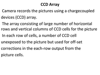
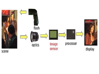
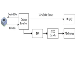
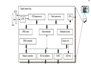
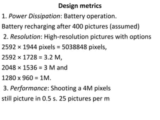
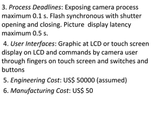
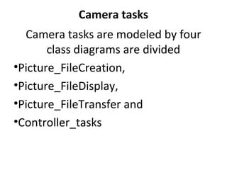
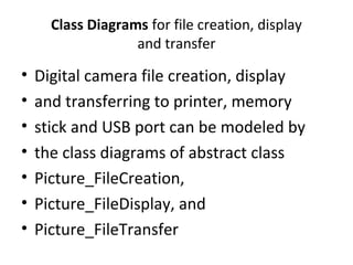
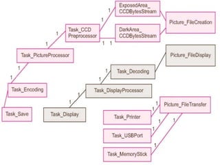
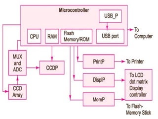
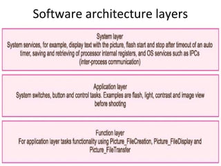
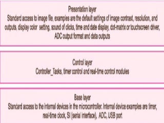
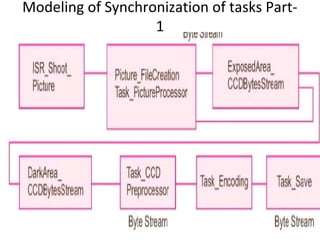
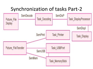

The document describes the hardware and software architecture of a digital camera. It discusses the key components including the CCD array for capturing images, memory for storage, and controllers for user input. It then outlines the main tasks of capturing and processing an image, encoding it into a file, displaying and transferring the file. Class diagrams are used to model the different tasks related to file creation, display, and transfer, with synchronization between tasks like the CCD processor and file creation managed through objects.


![casestudyofdigitalcamera-140715113252-phpapp01[1].pptx](https://cdn.slidesharecdn.com/ss_thumbnails/casestudyofdigitalcamera-140715113252-phpapp011-240904060527-344825f6-thumbnail.jpg?width=640&height=640&fit=bounds)