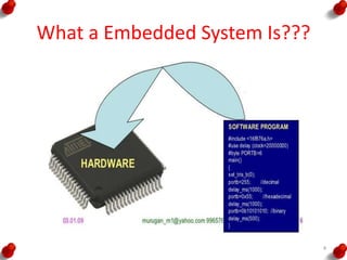
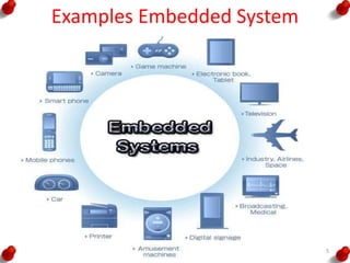
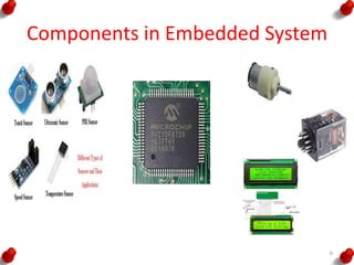
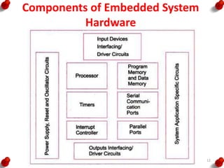
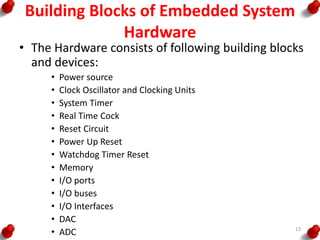
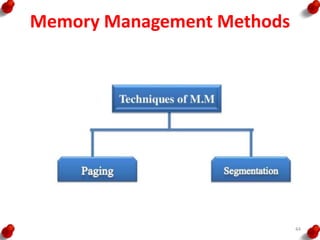
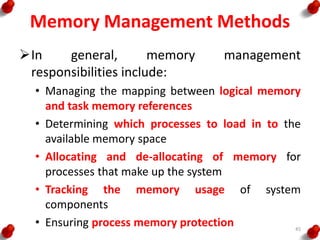
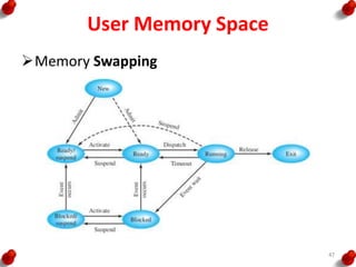
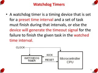
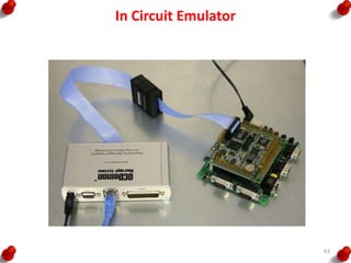
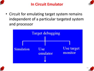
INTRODUCTION TO
EMBEDDED SYSTEMS
T.Ramprakash
AP/ECE
Ramco Institute of Technology
Rajapalayam
1
INTRODUCTION TO EMBEDDED SYSTEMS
• Introduction to Embedded Systems
• The Build process for embedded systems
• Structural units in Embedded processor
• Selection of processor
• Selection of Memory devices
2
INTRODUCTION TO EMBEDDED SYSTEMS
• DMA
• Memory management methods
• Timer and Counting devices
• Watchdog Timer
• Real Time Clock
• In circuit emulator
• Target Hardware Debugging. 3
What a Embedded System Is???
4
Examples Embedded System
5
Components in Embedded System
6
System
A system is a way of working, organizing or
doing one or many tasks, which are performed in
a system according to a fixed plan, program or
set or rules
7
General Computing System Components
• Microprocessor
• Large memory
• Input Units
• Out put Units
• Networking Units
• An Operating System
8
Embedded System
An embedded system is a system that has
embedded software in a computer hardware.
The system is dedicated for either an
application(s) or specific part of an application or
product or a component of a large system
Eg.
Washing machine
Cooking machine
Automative chocolate vending machines
Multitasking toys
9
Classification of Embedded System
i. Small Scale Embedded Systems
ii. Medium Scale Embedded Systems
iii. Sophisticated Embedded Systems
10
Embedded System Components
• It embeds Hardware similar to a computer
• Software usually embeds in the ROM, flash
memory or media card
• It embeds a Real Time Operation System
(RTOS)
11
Components of Embedded System
Hardware
12
Building Blocks of Embedded System
Hardware
• The Hardware consists of following building blocks
and devices:
• Power source
• Clock Oscillator and Clocking Units
• System Timer
• Real Time Cock
• Reset Circuit
• Power Up Reset
• Watchdog Timer Reset
• Memory
• I/O ports
• I/O buses
• I/O Interfaces
• DAC
• ADC 13
The Build Process
• The first step is selecting a processor
• The processor is selected from the following
considerations
– Instruction Set
– Maximum bits in an operand in an operation
– Clock frequency in MHz or GHz and the
processing speed in Million Instructions per
seconds
– Processor ability to solve the complex algorithms
used in meeting the deadlines for their processing
14
The Build Process
• The build process for embedding software
consists of the following steps
– Project file consisting of source file and library
files
– Compilation of the project files
– Linking all object files and locating onto a single
re-locatable object file
– Converting the object file in a form called hex-file
to binary image
15
The Build Process
16
Design Process in Embedded System
• Concepts used during Design process
– Abstraction
– Hardware and Software Architectures
– Extra Functional Properties
– System Related family of Designs
– Modular Design
– Mapping
– User Interfaces Design
– Refinements
17
Design Process in Embedded System
• Software Design Process
18
Design Process in Embedded System
• Design Metrics
– Power Dissipation
– Performance
– Process Deadlines
– User Interfaces
– Size
– Engineering Cost
– Manufacturing Cost
– Flexibility
– Prototype Development Time
– Time to Market
– System and User Safety
– Maintenance 19
Abstraction of Steps in Design Process
20
Structural Units in Embedded Processor
• Internal Buses:
– It internally connects all the structural units inside the processor.
– Its width can be 8,16,32 or 64 bits
• Address Bus
– It is the external bus that carries the address from the MAR to the memory as
well as the IO devices and the other units of the system
• Data Bus
– It is an external bus that carries the data from or to the address
• Control Bus
– It is an external bus to carry control signal between the processor and memory
devices
• Bus Interface Unit
– It is the interface unit between the processor’s internal units with the external
buses
• MAR:
– Memory Address Register
– It holds the address of the byte or word to be fetched from external memories
• MDR:
– It holds the byte or word fetched from/to external memory or I/O address
21
Structural Units in Embedded Processor
• Program Counter
– PC holds the memory address of the next instruction that would
be executed.
• Stack Pointer
– It is a pointer for an address which corresponds to stack top in
the memory
• Instruction Register
– It takes sequentially the instruction codes to the execution unit
of the processor
• Instruction Decoder
– It decodes the instruction opcode received at the IR passes it to
the processor CU
• Instruction Queue
– It is the queue of instruction so that the IR does not have to wait
for the next instruction after one has been carried out
22
Structural Units in Embedded Processor
• Arithmetic and Logical Unit
– It is a unit to execute arithmetic and logical instruction
according to the current instruction present in the IR
• Floating Point Processing Unit (FPPU)
– A unit separate from ALU for floating point processing
which is essential in processing mathematical
functions fast in a microprocessor or DSP
• Floating Point Register Set(FPRS):
– A register set dedicated for storing floating point
number in a standard format and used by FPPU for its
data and stack
23
Structural Units in Embedded Processor
• Control Unit
– It controls all the bus activities and unit functions
needed for processing
• Memory management Unit (MMU)
– It manages the memory such that instruction and
data are readily available for processing
• Application Register Set
– It is set of on-chip registers used during processing
the instruction of the application program of the
user
24
Structural Units in Embedded Processor
• Instruction Cache
– It sequentially store s, like an Instruction queue, the
instructions in FIFO.
• Data Cache
– It stores the pre-fetched data from the external
memory
– The data cache generally holds both the key and the
value together at the location
• Pre-Fetch Control Unit
– It is the unit that controls the prefetching of data into
the I-Cache and D-Cache in advance from the memory
units
– The instruction and data are delivered when needed
to the processor’s execution unit
25
Structural Units in Embedded Processor
• Register Window
– A register window consists of a subset of registers
with each subset storing static variables and status
words of a task or program thread.
• Advanced processing Unit
– These are units used for multi stage pipeline
processing, multiline superscalar processing to obtain
processing speed higher that one instruction per
clock cycle
• Atomic Operations Unit (AOU ):
– It lets a user instruction when broken into number of
processor instruction called atomic operation, finish
before an interrupt of a process occurs. 26
Structural Units in Embedded Processor
27
Embedded System Characteristics
• System functions in real time
• Program is preloaded in the ROM(s) or flash
memory
• Dedicated set of functions
• Complex dedicated purpose preprogrammed
– algorithms
– Hardware
– Graphics and Other user interfaces
• Multirate operations with different
predetermined time constraints to finish the
different operations 28
Constraints of Embedded Systems
• Available System Memory
• Available Processor Speed
• Meeting Deadlines
• Performance
• Power
• Size
• Design and Manufacturing Cost 29
Selection of Processor
• Different systems require different processor
features
• The processor is selected from the following
considerations
– Instruction Set
– Maximum bits in an operand in an operation
– Processing Speed
– Ability to solve the complex algorithms
– A processor gives high computing performance when
it has
• Pipeline and Superscalar architecture
• Pre-fetch cache unit, caches, register files and MMU
• RISC core architecture 30
Selection of Processor
– A processor with register windows provides fast
context switching in a multitasking system
– Processor has auto shut down features for its
units
– A processor with burst mode accesses external
memories fast
31
Selection of Memory Devices
• Software designer coding is over and the ROM
image file is ready, a hardware designer of a
system is faced with the a questions, of
– what type of memory ?
– what to use?
– how much size of each, should be to used???
32
Selection of Memory Devices
• Some of the selection process is,
– Internal ROM
– Internal EPROM
– Internal EEPROM
– Internal RAM
– ROM Device
– EPROM Device
– EEPROM Device
– Flash Device
– RAM device
– Parameterized Distributed RAM
– Parameterized Block RAM 33
Selection of Memory Devices
• Masked ROM or EPROM stores the embedded
software
• EEPROM is used for testing and design stages
and also is used to store the results during the
system program run time
• Flash stores the results byte by byte during a
system run after a full sector erase
• RAM is mostly used in SRAM form in a system
• Sophisticated system use RAM in the form of
DRAM, SDRAM or RDRAM
• Parameterized distributed RAM is used when the
I/O devices and subunits require a memory buffer
and a fast write by another system 34
DMA
• I/O devices need to transfer the data of other
systems to the memory addresses in the
system
• A system may also need to transfer data to the
IO devices
• A Direct Memory Access is required when a
block of data is to be transferred between two
systems without the CPU intervening, except
at the start and at the end
35
DMA
36
DMA
• DMA supports 3 modes of operations
– Single transfer at a time and then release of the
hold on the system bus
– Burst transfer at a time and then release of the
hold on the system bus. A burst may be a few Kilo
Bytes
– Bulk transfer and then release of the hold on the
system bus after the transfer is completed
37
DMAC
• DMA transfer is facilitated by the DMAC (DMA
Controller)
• Data transfer occurs efficiently between I/O
devices and system memory with the least
processor intervention using DMAC
• The system address and data buses become
unavailable to the processor and available to the
IO device that connects DMAC 38
DMA
A typical DMA controller includes three
registers
Starting Address Register
Length Register
Status Register
39
DMA
40
DMAC
41
Memory Management Methods
42
Memory Management Methods
How MMU works
Keep track of what part of memory are in use
Allocate memory to processes when needed
De-allocate when processes are done
Swapping or Paging between main memory and
disk
43
Memory Management Methods
44
Memory Management Methods
In general, memory management
responsibilities include:
• Managing the mapping between logical memory
and task memory references
• Determining which processes to load in to the
available memory space
• Allocating and de-allocating of memory for
processes that make up the system
• Tracking the memory usage of system
components
• Ensuring process memory protection 45
User Memory Space
Because multiple processes are sharing the
same physical memory when being loaded
into RAM for processing, there also must be
some protection mechanism so processes
cannot unintentionally affect each other when
being swapped in and out of a single physical
memory space
These issues are typically resolved by the OS
through “memory swapping” where partitions
of memory are swapped at run time.
46
User Memory Space
Memory Swapping
47
User Memory Space
48
Segmentation
A process encapsulates all the information that is
involved in executing a program, including source
code, stack and data.
All of the different types of information within a
process are divided into logical memory units of
variable sizes called SEGMENTS
Most OS typically allow processes to have all or
some combination of five types of information
within segments such as
Code Segment
Data Segment
Block started by Symbol
Stack Segment
Heap Segment
49
Typical Memory Allocation Schemes include:
First Fit
It scans from the beginning for the first ‘Hole’ that is
large enough
Next Fit
It scans from where the last search ended for the next
‘Hole’ that is large enough
Best Fit
It scans the entire list for the hole that best fits the
new data
Worst Fit
It places data in the largest available “hole”
Quick Fit
Here, list is kept with memory sizes. Allocation is done
from this information 50
Memory Management Functions
• Allocation and De-allocation
• Dynamic Blocks Allocation
• Memory Protection to the OS functions
• Memory Protection among the Tasks
• Multiprocessor Memory Allocation
51
Timer and Counting Devices
52
Timer and Counting Devices
• Timer Device
– A timer device is a device which counts the input
at the regular interval of the clock pulses
– The count are stored and incremented on each
pulse
– The timer gives output bits for the present counts
– The counts multiplied by the interval give the
time
– It has a input pin for resetting it for all count
bits = 0s
– It has an output pin for output when all counts
bits =0s after reaching the maximum value 53
Timer States
54
Timer and Counting Devices
• Counting Devices
– A counting device is a device which counts the
input due to the events at irregular or regular
intervals
– The counts give the number of input events or
pulses since it was last read
– Has a register to enable read of present counts
– Functions as timer when counting regular interval
clock pulses
– When a timer or counter becomes 0x00 or 0x0000
after 0xFF or 0xFFFF (maximum value), it can
generate an ‘interrupt’, or an output ‘Time-Out’
or set a status bit ‘TOV’ 55
Hardware Timer
56
Hardware Timer
• Control Bits are of 9 types,
I. Timer Enable (To activate a timer)
II. Timer start (to start counting at each clock input)
III. Timer stop (to stop counting)
IV. Pre-scaling Bits (to divide the clock out frequency signal from
the processor)
V. Up count Enable (To enable counting up by incrementing the
count value on each clock input)
VI. Down count enable (to decrement on a clock input)
VII. Load enable (To enable loading of a value at a register into the
timer)
VIII.Timer Interrupt Enable (To enable interrupt when the timer
count value reaches 0)
IX. Time out enable (To enable a signal when the timer overflows)57
Free running Counter
• A counting device may be a free running (blind
counting) device giving overflow interrupts at fixed
intervals
• A pre-scalar for the clock input pulses to fix the
intervals
58
Control bits, Status flags and variables of a
software timer
59
Uses of a timer device
• Initiating an event after a comparison(s) with
between the pre-set time with counted value.
• Watchdog timer - It resets the system after a
defined time
• Input pulse counting when using a timer,
which is ticked by giving non-periodic inputs
instead of the clock inputs.
60
Watchdog Timers
• A watchdog timer is a timing device that is set
for a preset time interval and a set of task
must finish during that intervals, or else the
device will generate the timeout signal for the
failure to finish the given task in the watched
time interval.
61
Real Time Clocks
• A clock, which is based on the interrupts at
pre-set intervals.
• An interrupt service routine executes on each
timeout (overflow) of this clock.
• This timing device once started never resets
or never reloaded with another value.
• Once it is set, it is not modified later.
• Used in a system to save the time and date.
• Used in a system to initiate return of control
to the system (OS) after the set system clock
periods
62
In Circuit Emulator
63
In Circuit Emulator
• Circuit for emulating target system remains
independent of a particular targeted system
and processor
64
In Circuit Emulator
• A circuit for emulating target system remains
independent of a particular targeted system
and processor
• Emulator or ICE provides great flexibility and
ease for developing various applications on a
single system in place of testing that multiple
targeted systems.
65
An Emulator
66
In Circuit Emulator
67
Emulator
• Emulates MCU inputs from sensors
• Emulates controlled outputs for the peripheral
interfaces/systems
• Emulates target MCU IOs and socket to
connect externally MCU
68
ICE
• Means In-Circuit Emulator
• Interface COM port of a computer
• Emulates target MCU IOs
• ICE socket connects MCU externally
• Uses computer developed object files and hex
files for the MCU
• Uses debugger at the computer developed
files for the MCU application
69
Target Hardware Debugging
70
Host-Target System Development Approach
• During development process, a host system is
used
• Then locating and burning the codes in the
target board.
• Target board hardware and software later
copied to get the final embedded system
• Final system functions exactly as the one
tested and debugged and finalized during the
development process
71
Host System (PC or Laptop or Workstation)
• High performance processor with caches, large
RAM memory
• ROMBIOS (read only memory basic input-output
system)
• Very large memory on disk
• Keyboard
• Display monitor
• Mice
• Network connection
• Program development kit for a high level
language program or IDE
• Host processor compiler and Cross Compiler
• Cross assembler 72
Program Development Tool Kit at host
• Program development tool kit or IDE
• Editor─ used for writing C codes or assembly
mnemonics or C++ or Java or Visual C++ using
the keyboard of the host system (PC) for
entering the program.
• Using GUIs for allowing the entry, addition,
deletion, insert, appending previously written
lines or files, merging record and files at the
specific positions.
73
Program Development Tool Kit at host
• Create source file that stores the edited file.
• File given an appropriate name by the
programmer
• Can use previously created files
• Can also integrate the various source files.
• Can save different versions of the source files.
• Compiler, cross compiler, assembler, cross
assembler 74
Target System
75
Sophisticated Target System
76
Sophisticated Target System
• Target system differs from a final system
• Target system interfaces with the computer as
well as works as a standalone system
• In target system might be repeated downloading
of the codes during the development phase.
• Target system copy made that later on functions
as embedded system
• Designer later on simply copies it into final
system or product.
• Final system may employs ROM in place of flash,
EEPROM or EPROM in embedded system. 77
INTRODUCTION TO EMBEDDED SYSTEMS
• Introduction to Embedded Systems
• The Build process for embedded systems (2)
• Structural units in Embedded processor(2)
• Selection of processor(1)
• Selection of Memory devices (1)
78
Reference
1. Rajkamal, ‘Embedded System-Architecture,
Programming, Design’, Mc Graw Hill, 2013.
2. Peckol, “Embedded system Design”, John Wiley &
Sons, 2010.
3. Lyla B Das,” Embedded Systems-An Integrated
Approach”, Pearson, 2013.
79

Introduction to embedded systems

  • 1.
  • 2.
    INTRODUCTION TO EMBEDDEDSYSTEMS • Introduction to Embedded Systems • The Build process for embedded systems • Structural units in Embedded processor • Selection of processor • Selection of Memory devices 2
  • 3.
    INTRODUCTION TO EMBEDDEDSYSTEMS • DMA • Memory management methods • Timer and Counting devices • Watchdog Timer • Real Time Clock • In circuit emulator • Target Hardware Debugging. 3
  • 4.
    What a EmbeddedSystem Is??? 4
  • 5.
  • 6.
  • 7.
    System A system isa way of working, organizing or doing one or many tasks, which are performed in a system according to a fixed plan, program or set or rules 7
  • 8.
    General Computing SystemComponents • Microprocessor • Large memory • Input Units • Out put Units • Networking Units • An Operating System 8
  • 9.
    Embedded System An embeddedsystem is a system that has embedded software in a computer hardware. The system is dedicated for either an application(s) or specific part of an application or product or a component of a large system Eg. Washing machine Cooking machine Automative chocolate vending machines Multitasking toys 9
  • 10.
    Classification of EmbeddedSystem i. Small Scale Embedded Systems ii. Medium Scale Embedded Systems iii. Sophisticated Embedded Systems 10
  • 11.
    Embedded System Components •It embeds Hardware similar to a computer • Software usually embeds in the ROM, flash memory or media card • It embeds a Real Time Operation System (RTOS) 11
  • 12.
    Components of EmbeddedSystem Hardware 12
  • 13.
    Building Blocks ofEmbedded System Hardware • The Hardware consists of following building blocks and devices: • Power source • Clock Oscillator and Clocking Units • System Timer • Real Time Cock • Reset Circuit • Power Up Reset • Watchdog Timer Reset • Memory • I/O ports • I/O buses • I/O Interfaces • DAC • ADC 13
  • 14.
    The Build Process •The first step is selecting a processor • The processor is selected from the following considerations – Instruction Set – Maximum bits in an operand in an operation – Clock frequency in MHz or GHz and the processing speed in Million Instructions per seconds – Processor ability to solve the complex algorithms used in meeting the deadlines for their processing 14
  • 15.
    The Build Process •The build process for embedding software consists of the following steps – Project file consisting of source file and library files – Compilation of the project files – Linking all object files and locating onto a single re-locatable object file – Converting the object file in a form called hex-file to binary image 15
  • 16.
  • 17.
    Design Process inEmbedded System • Concepts used during Design process – Abstraction – Hardware and Software Architectures – Extra Functional Properties – System Related family of Designs – Modular Design – Mapping – User Interfaces Design – Refinements 17
  • 18.
    Design Process inEmbedded System • Software Design Process 18
  • 19.
    Design Process inEmbedded System • Design Metrics – Power Dissipation – Performance – Process Deadlines – User Interfaces – Size – Engineering Cost – Manufacturing Cost – Flexibility – Prototype Development Time – Time to Market – System and User Safety – Maintenance 19
  • 20.
    Abstraction of Stepsin Design Process 20
  • 21.
    Structural Units inEmbedded Processor • Internal Buses: – It internally connects all the structural units inside the processor. – Its width can be 8,16,32 or 64 bits • Address Bus – It is the external bus that carries the address from the MAR to the memory as well as the IO devices and the other units of the system • Data Bus – It is an external bus that carries the data from or to the address • Control Bus – It is an external bus to carry control signal between the processor and memory devices • Bus Interface Unit – It is the interface unit between the processor’s internal units with the external buses • MAR: – Memory Address Register – It holds the address of the byte or word to be fetched from external memories • MDR: – It holds the byte or word fetched from/to external memory or I/O address 21
  • 22.
    Structural Units inEmbedded Processor • Program Counter – PC holds the memory address of the next instruction that would be executed. • Stack Pointer – It is a pointer for an address which corresponds to stack top in the memory • Instruction Register – It takes sequentially the instruction codes to the execution unit of the processor • Instruction Decoder – It decodes the instruction opcode received at the IR passes it to the processor CU • Instruction Queue – It is the queue of instruction so that the IR does not have to wait for the next instruction after one has been carried out 22
  • 23.
    Structural Units inEmbedded Processor • Arithmetic and Logical Unit – It is a unit to execute arithmetic and logical instruction according to the current instruction present in the IR • Floating Point Processing Unit (FPPU) – A unit separate from ALU for floating point processing which is essential in processing mathematical functions fast in a microprocessor or DSP • Floating Point Register Set(FPRS): – A register set dedicated for storing floating point number in a standard format and used by FPPU for its data and stack 23
  • 24.
    Structural Units inEmbedded Processor • Control Unit – It controls all the bus activities and unit functions needed for processing • Memory management Unit (MMU) – It manages the memory such that instruction and data are readily available for processing • Application Register Set – It is set of on-chip registers used during processing the instruction of the application program of the user 24
  • 25.
    Structural Units inEmbedded Processor • Instruction Cache – It sequentially store s, like an Instruction queue, the instructions in FIFO. • Data Cache – It stores the pre-fetched data from the external memory – The data cache generally holds both the key and the value together at the location • Pre-Fetch Control Unit – It is the unit that controls the prefetching of data into the I-Cache and D-Cache in advance from the memory units – The instruction and data are delivered when needed to the processor’s execution unit 25
  • 26.
    Structural Units inEmbedded Processor • Register Window – A register window consists of a subset of registers with each subset storing static variables and status words of a task or program thread. • Advanced processing Unit – These are units used for multi stage pipeline processing, multiline superscalar processing to obtain processing speed higher that one instruction per clock cycle • Atomic Operations Unit (AOU ): – It lets a user instruction when broken into number of processor instruction called atomic operation, finish before an interrupt of a process occurs. 26
  • 27.
    Structural Units inEmbedded Processor 27
  • 28.
    Embedded System Characteristics •System functions in real time • Program is preloaded in the ROM(s) or flash memory • Dedicated set of functions • Complex dedicated purpose preprogrammed – algorithms – Hardware – Graphics and Other user interfaces • Multirate operations with different predetermined time constraints to finish the different operations 28
  • 29.
    Constraints of EmbeddedSystems • Available System Memory • Available Processor Speed • Meeting Deadlines • Performance • Power • Size • Design and Manufacturing Cost 29
  • 30.
    Selection of Processor •Different systems require different processor features • The processor is selected from the following considerations – Instruction Set – Maximum bits in an operand in an operation – Processing Speed – Ability to solve the complex algorithms – A processor gives high computing performance when it has • Pipeline and Superscalar architecture • Pre-fetch cache unit, caches, register files and MMU • RISC core architecture 30
  • 31.
    Selection of Processor –A processor with register windows provides fast context switching in a multitasking system – Processor has auto shut down features for its units – A processor with burst mode accesses external memories fast 31
  • 32.
    Selection of MemoryDevices • Software designer coding is over and the ROM image file is ready, a hardware designer of a system is faced with the a questions, of – what type of memory ? – what to use? – how much size of each, should be to used??? 32
  • 33.
    Selection of MemoryDevices • Some of the selection process is, – Internal ROM – Internal EPROM – Internal EEPROM – Internal RAM – ROM Device – EPROM Device – EEPROM Device – Flash Device – RAM device – Parameterized Distributed RAM – Parameterized Block RAM 33
  • 34.
    Selection of MemoryDevices • Masked ROM or EPROM stores the embedded software • EEPROM is used for testing and design stages and also is used to store the results during the system program run time • Flash stores the results byte by byte during a system run after a full sector erase • RAM is mostly used in SRAM form in a system • Sophisticated system use RAM in the form of DRAM, SDRAM or RDRAM • Parameterized distributed RAM is used when the I/O devices and subunits require a memory buffer and a fast write by another system 34
  • 35.
    DMA • I/O devicesneed to transfer the data of other systems to the memory addresses in the system • A system may also need to transfer data to the IO devices • A Direct Memory Access is required when a block of data is to be transferred between two systems without the CPU intervening, except at the start and at the end 35
  • 36.
  • 37.
    DMA • DMA supports3 modes of operations – Single transfer at a time and then release of the hold on the system bus – Burst transfer at a time and then release of the hold on the system bus. A burst may be a few Kilo Bytes – Bulk transfer and then release of the hold on the system bus after the transfer is completed 37
  • 38.
    DMAC • DMA transferis facilitated by the DMAC (DMA Controller) • Data transfer occurs efficiently between I/O devices and system memory with the least processor intervention using DMAC • The system address and data buses become unavailable to the processor and available to the IO device that connects DMAC 38
  • 39.
    DMA A typical DMAcontroller includes three registers Starting Address Register Length Register Status Register 39
  • 40.
  • 41.
  • 42.
  • 43.
    Memory Management Methods HowMMU works Keep track of what part of memory are in use Allocate memory to processes when needed De-allocate when processes are done Swapping or Paging between main memory and disk 43
  • 44.
  • 45.
    Memory Management Methods Ingeneral, memory management responsibilities include: • Managing the mapping between logical memory and task memory references • Determining which processes to load in to the available memory space • Allocating and de-allocating of memory for processes that make up the system • Tracking the memory usage of system components • Ensuring process memory protection 45
  • 46.
    User Memory Space Becausemultiple processes are sharing the same physical memory when being loaded into RAM for processing, there also must be some protection mechanism so processes cannot unintentionally affect each other when being swapped in and out of a single physical memory space These issues are typically resolved by the OS through “memory swapping” where partitions of memory are swapped at run time. 46
  • 47.
  • 48.
  • 49.
    Segmentation A process encapsulatesall the information that is involved in executing a program, including source code, stack and data. All of the different types of information within a process are divided into logical memory units of variable sizes called SEGMENTS Most OS typically allow processes to have all or some combination of five types of information within segments such as Code Segment Data Segment Block started by Symbol Stack Segment Heap Segment 49
  • 50.
    Typical Memory AllocationSchemes include: First Fit It scans from the beginning for the first ‘Hole’ that is large enough Next Fit It scans from where the last search ended for the next ‘Hole’ that is large enough Best Fit It scans the entire list for the hole that best fits the new data Worst Fit It places data in the largest available “hole” Quick Fit Here, list is kept with memory sizes. Allocation is done from this information 50
  • 51.
    Memory Management Functions •Allocation and De-allocation • Dynamic Blocks Allocation • Memory Protection to the OS functions • Memory Protection among the Tasks • Multiprocessor Memory Allocation 51
  • 52.
  • 53.
    Timer and CountingDevices • Timer Device – A timer device is a device which counts the input at the regular interval of the clock pulses – The count are stored and incremented on each pulse – The timer gives output bits for the present counts – The counts multiplied by the interval give the time – It has a input pin for resetting it for all count bits = 0s – It has an output pin for output when all counts bits =0s after reaching the maximum value 53
  • 54.
  • 55.
    Timer and CountingDevices • Counting Devices – A counting device is a device which counts the input due to the events at irregular or regular intervals – The counts give the number of input events or pulses since it was last read – Has a register to enable read of present counts – Functions as timer when counting regular interval clock pulses – When a timer or counter becomes 0x00 or 0x0000 after 0xFF or 0xFFFF (maximum value), it can generate an ‘interrupt’, or an output ‘Time-Out’ or set a status bit ‘TOV’ 55
  • 56.
  • 57.
    Hardware Timer • ControlBits are of 9 types, I. Timer Enable (To activate a timer) II. Timer start (to start counting at each clock input) III. Timer stop (to stop counting) IV. Pre-scaling Bits (to divide the clock out frequency signal from the processor) V. Up count Enable (To enable counting up by incrementing the count value on each clock input) VI. Down count enable (to decrement on a clock input) VII. Load enable (To enable loading of a value at a register into the timer) VIII.Timer Interrupt Enable (To enable interrupt when the timer count value reaches 0) IX. Time out enable (To enable a signal when the timer overflows)57
  • 58.
    Free running Counter •A counting device may be a free running (blind counting) device giving overflow interrupts at fixed intervals • A pre-scalar for the clock input pulses to fix the intervals 58
  • 59.
    Control bits, Statusflags and variables of a software timer 59
  • 60.
    Uses of atimer device • Initiating an event after a comparison(s) with between the pre-set time with counted value. • Watchdog timer - It resets the system after a defined time • Input pulse counting when using a timer, which is ticked by giving non-periodic inputs instead of the clock inputs. 60
  • 61.
    Watchdog Timers • Awatchdog timer is a timing device that is set for a preset time interval and a set of task must finish during that intervals, or else the device will generate the timeout signal for the failure to finish the given task in the watched time interval. 61
  • 62.
    Real Time Clocks •A clock, which is based on the interrupts at pre-set intervals. • An interrupt service routine executes on each timeout (overflow) of this clock. • This timing device once started never resets or never reloaded with another value. • Once it is set, it is not modified later. • Used in a system to save the time and date. • Used in a system to initiate return of control to the system (OS) after the set system clock periods 62
  • 63.
  • 64.
    In Circuit Emulator •Circuit for emulating target system remains independent of a particular targeted system and processor 64
  • 65.
    In Circuit Emulator •A circuit for emulating target system remains independent of a particular targeted system and processor • Emulator or ICE provides great flexibility and ease for developing various applications on a single system in place of testing that multiple targeted systems. 65
  • 66.
  • 67.
  • 68.
    Emulator • Emulates MCUinputs from sensors • Emulates controlled outputs for the peripheral interfaces/systems • Emulates target MCU IOs and socket to connect externally MCU 68
  • 69.
    ICE • Means In-CircuitEmulator • Interface COM port of a computer • Emulates target MCU IOs • ICE socket connects MCU externally • Uses computer developed object files and hex files for the MCU • Uses debugger at the computer developed files for the MCU application 69
  • 70.
  • 71.
    Host-Target System DevelopmentApproach • During development process, a host system is used • Then locating and burning the codes in the target board. • Target board hardware and software later copied to get the final embedded system • Final system functions exactly as the one tested and debugged and finalized during the development process 71
  • 72.
    Host System (PCor Laptop or Workstation) • High performance processor with caches, large RAM memory • ROMBIOS (read only memory basic input-output system) • Very large memory on disk • Keyboard • Display monitor • Mice • Network connection • Program development kit for a high level language program or IDE • Host processor compiler and Cross Compiler • Cross assembler 72
  • 73.
    Program Development ToolKit at host • Program development tool kit or IDE • Editor─ used for writing C codes or assembly mnemonics or C++ or Java or Visual C++ using the keyboard of the host system (PC) for entering the program. • Using GUIs for allowing the entry, addition, deletion, insert, appending previously written lines or files, merging record and files at the specific positions. 73
  • 74.
    Program Development ToolKit at host • Create source file that stores the edited file. • File given an appropriate name by the programmer • Can use previously created files • Can also integrate the various source files. • Can save different versions of the source files. • Compiler, cross compiler, assembler, cross assembler 74
  • 75.
  • 76.
  • 77.
    Sophisticated Target System •Target system differs from a final system • Target system interfaces with the computer as well as works as a standalone system • In target system might be repeated downloading of the codes during the development phase. • Target system copy made that later on functions as embedded system • Designer later on simply copies it into final system or product. • Final system may employs ROM in place of flash, EEPROM or EPROM in embedded system. 77
  • 78.
    INTRODUCTION TO EMBEDDEDSYSTEMS • Introduction to Embedded Systems • The Build process for embedded systems (2) • Structural units in Embedded processor(2) • Selection of processor(1) • Selection of Memory devices (1) 78
  • 79.
    Reference 1. Rajkamal, ‘EmbeddedSystem-Architecture, Programming, Design’, Mc Graw Hill, 2013. 2. Peckol, “Embedded system Design”, John Wiley & Sons, 2010. 3. Lyla B Das,” Embedded Systems-An Integrated Approach”, Pearson, 2013. 79