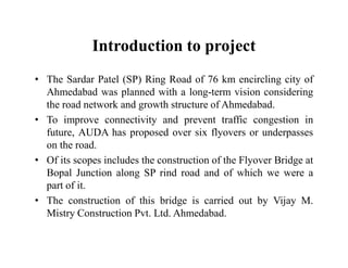
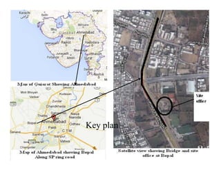
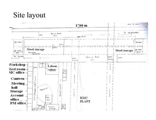
The document provides details about the construction of a flyover bridge along the SP Ring Road in Ahmedabad, India. Some key details include:
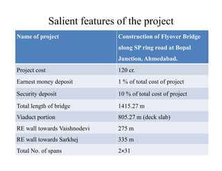
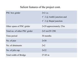
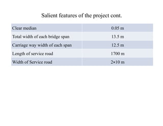
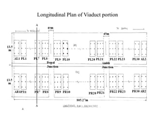
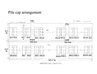
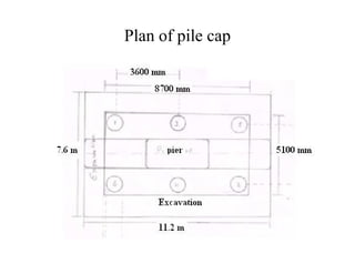
- The project involves constructing a 1,415 meter long flyover bridge with 30 piers and 32 pile caps.
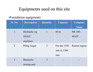
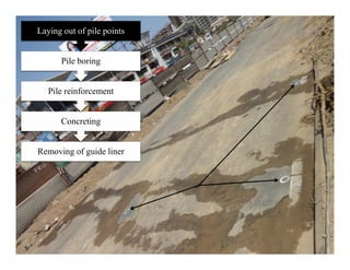
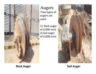
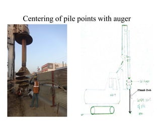
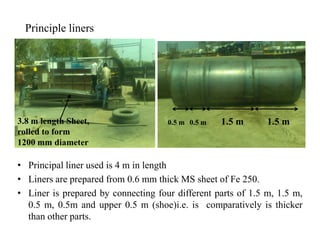
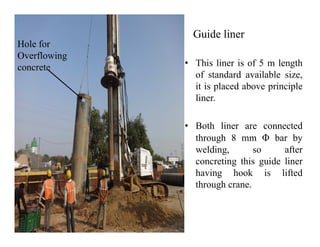
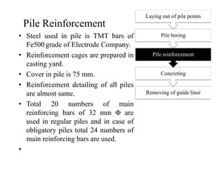
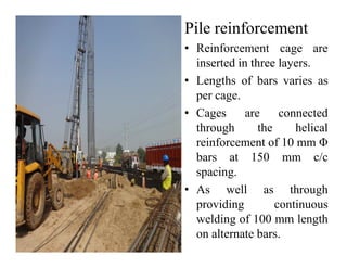
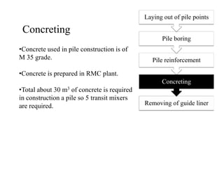
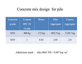
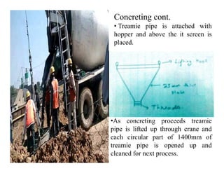
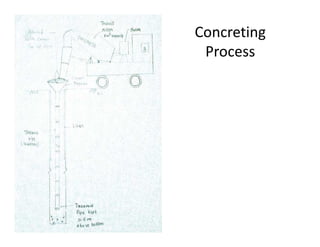
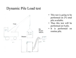
- Pile construction is a major aspect of the project, with 408 piles of 1,200 mm diameter being constructed using a hydraulic rig by boring and concreting.
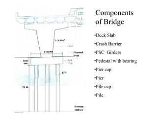
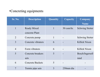
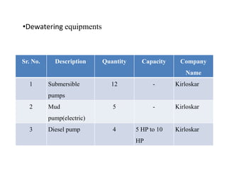
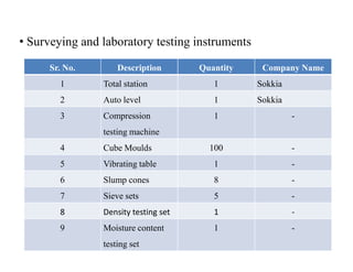
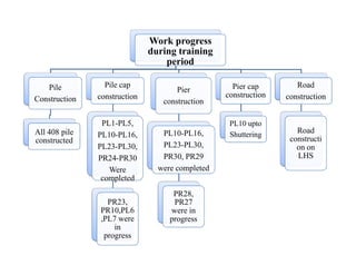
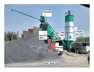
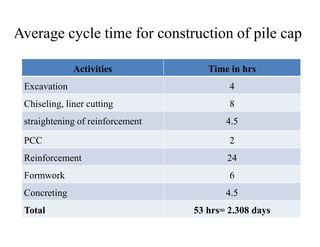
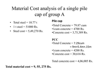
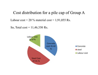
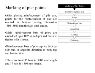
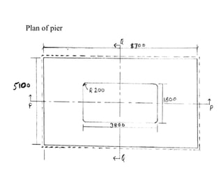
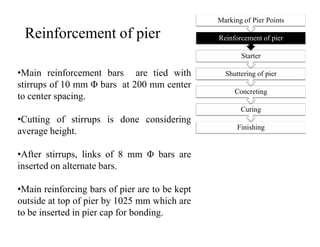
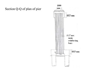
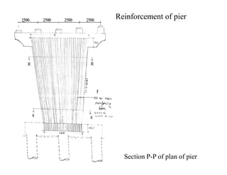
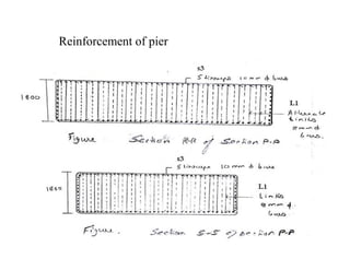
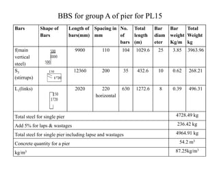
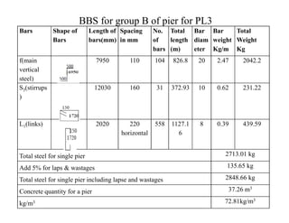
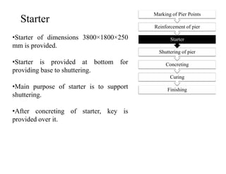
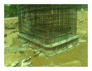
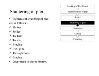
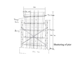
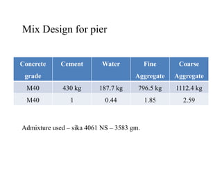
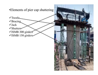
- Other construction activities discussed include pile cap construction, pier construction, road construction and the use of various equipment.
- The flyover is expected to improve connectivity and prevent traffic congestion along the busy SP Ring Road in Ahmedabad.
Pile foundation is important for construction of foundation where bearing capacity of soil is poor. Pile foundation is use for distribution of uneven load of superstructure.There are so many type of pile are use for construction. Here i present some of pile with suitable condition for construction and methods for construction.
Thank you.
This is useful for civil engineering students in their subject Building construction offered by GTU. This presentation includes Timbering of trenches, Scaffolding, Shoring 7 underpinning techniques used in construction of building for temporary period of time.
Joints are easy to maintain and are less detrimental than uncontrolled or uneven cracks. Concrete expands & shrinks with variations in moisture and temp. The overall affinity is to shrink and this can cause cracking at an early age. Uneven cracks are unpleasant and difficult to maintain but usually do not affect the integrity of concrete.
pipe expansion joint us bellows us bellows catalogue rubber expansion joint metal expansion joints driveway expansion joint filler flexi craft expansion joints building expansion joint systems
construction joint vs expansion joint construction joint vs control joint sidewalk control joint spacing concrete wall control joints expansion joint concrete construction joint concrete concrete joints control joint
monolithic isolation joints isolation joint material isolation joint vs expansion joint isolation joint neo prene insulating joints pipeline isolation joint vs control joint isolation joints in concrete concrete slab isolation joint
construction joint vs expansion joint construction joint vs control joints idewalk control joint spacing concrete wall control joints expansion joint concrete construction joint concrete concrete joints control joint
concrete joint filler
concrete joint filler strips
control joint vs construction joint concrete
concrete control joint filler
concrete slab control joint detail
types of concrete expansion joints
construction joint concrete
control joints in concrete
One way slab and two way slab- Difference betweenCivil Insider
Get PPT here
https://civilinsider.com/difference-between-one-way-slab-and-two-way-slab/
What is a Slab?
Slabs are the one of the most widely used structural elements whose depth is considerably smaller than rest of the dimensions. Basically slabs are used as roofs and floors in buildings, roof and bottom on water tanks, on bridges etc.
Slabs support and transfer load i.e. Dead load and live load, to columns by shear, flexure, and torsion. Slabs also help in reducing the effects of lateral wind loads and earthquake loads.
What is One Way Slab?
One way slabs are the slabs in which most of the loads are carried on the shorter span. The ratio of longer span to shorter span is equal to or greater than two or when the slab is supported by beams only along two opposite sides slab then the slab behaves as a One-way slab.
What is Two Way Slab?
Two-way slabs are the slabs in which loads are carried on both of the spans. The ratio of longer span to shorter span is less than two and when the slab is supported by beams along all the sides then the slab behaves as a two-way slab.
Difference Between One Way Slab and Two Way Slab
Here is the some basic information regarding Tunneling & Rock Drilling Equipments which I have collected from different resources (Internet,Professors,Experts,Engineers,Companies etc). It would be very helpful for M.Tech students of Construction Engineering & Management.
-RAJARSHI
It is used as a mould for a structure in which fresh concrete is poured only to harden subsequently.
formwork for concrete slab
beam formwork
steel formwork
doka h20
types of formwork
formwork for concrete
what is formwork in construction
building formwork
plywood disadvantages
advantage plywood
advantages and disadvantages of wood
best plywood for formwork
plywood formwork for concrete
mdf advantages and disadvantages
examples of advantages and disadvantages
advantage steel and construction
advantages of steel
disadvantages of steel structures
examples of advantages and disadvantages
advantages and disadvantages of surveys
wiki advantages and disadvantages
steel formwork design
steel formwork system
Aluminium Formwork Vs Conventional Formworkchaitanyakrsk
This technical paper covers the information about formwork introduction, types of formworks and mainly about the comparing aluminium formwork with conventional formwork. Data compiled from various prominent resources and from the experience gained over the years.
It is the presentation based on precast concrete construction which includes each and every point and scope which may be useful to civil engineering students
Бирюза приносит счастье в любви, устанавливает мир в семье, привлекает друзей и возбуждает симпатии к своему владельцу.
Она приносит благополучие и достаток (привлекает деньги к владельцу), усиливает интуицию, делает человека честолюбивым, храбрым, предусмотрительным, проницательным, охраняет своего владельца.
Бирюза является символом верной любви.
Изделия из бирюзы носят как амулет, приносящий победу, удачу, уверенность и положительные эмоции. Она помогает своему владельцу сосредоточиться, понять смысл жизни, определить, каких целей он должен добиваться.
Путешественникам следует брать с собой бирюзу в дорогу - она сделает путешествие легким и приятным.
Trabajo realizado para la clase de Ciencias de la Tierra y el medio ambiente, uno opcional que trata sobre los diversos fenómenos ambientales que ocurren en nuestro planeta y quizá no estemos concienciados de ellos.
Considero que esta estrategia puede ser muy útil para toda la sociedad en general puesto a que nos ayuda en todos los momentos de nuestra vida en el ámbito que cada quien decida utilizarlo. Principalmente que los padres incorporen a sus hijos a actividades como estas ya que son muy eficaces para el desarrollo y educación social y psicológico de sus hijos. con actividades como esta podríamos hacer del mundo un ligar mejor.
Growing of Precast construction system has given emphasis on improving work zone safety, reducing construction time and environmental impact, while maintaining the quality. The connections are the most important part of precast construction systems, being the general behavior of the precast structures related to their design, construction and performance. In this civil engineering project a trial to compare the strength of three types of portal frames viz. Monolithic Portal Frame, Portal Frame with corbel and Portal Frame without corbel and their deflections at various loads were observed and derived conclusion which one is efficient among all frames designed and cast.
Every Step you need in planning to extend a working open cast mine to underground mine on reaching a pit bottom.
Step-wise procedure to be followed is clearly mentioned.
Justifies the Indian Laws.
Sublevel Stoping method is explained in detail.
Case study of a copper mine is presented for eg.
NO1 Uk best vashikaran specialist in delhi vashikaran baba near me online vas...Amil Baba Dawood bangali
Contact with Dawood Bhai Just call on +92322-6382012 and we'll help you. We'll solve all your problems within 12 to 24 hours and with 101% guarantee and with astrology systematic. If you want to take any personal or professional advice then also you can call us on +92322-6382012 , ONLINE LOVE PROBLEM & Other all types of Daily Life Problem's.Then CALL or WHATSAPP us on +92322-6382012 and Get all these problems solutions here by Amil Baba DAWOOD BANGALI
#vashikaranspecialist #astrologer #palmistry #amliyaat #taweez #manpasandshadi #horoscope #spiritual #lovelife #lovespell #marriagespell#aamilbabainpakistan #amilbabainkarachi #powerfullblackmagicspell #kalajadumantarspecialist #realamilbaba #AmilbabainPakistan #astrologerincanada #astrologerindubai #lovespellsmaster #kalajaduspecialist #lovespellsthatwork #aamilbabainlahore#blackmagicformarriage #aamilbaba #kalajadu #kalailam #taweez #wazifaexpert #jadumantar #vashikaranspecialist #astrologer #palmistry #amliyaat #taweez #manpasandshadi #horoscope #spiritual #lovelife #lovespell #marriagespell#aamilbabainpakistan #amilbabainkarachi #powerfullblackmagicspell #kalajadumantarspecialist #realamilbaba #AmilbabainPakistan #astrologerincanada #astrologerindubai #lovespellsmaster #kalajaduspecialist #lovespellsthatwork #aamilbabainlahore #blackmagicforlove #blackmagicformarriage #aamilbaba #kalajadu #kalailam #taweez #wazifaexpert #jadumantar #vashikaranspecialist #astrologer #palmistry #amliyaat #taweez #manpasandshadi #horoscope #spiritual #lovelife #lovespell #marriagespell#aamilbabainpakistan #amilbabainkarachi #powerfullblackmagicspell #kalajadumantarspecialist #realamilbaba #AmilbabainPakistan #astrologerincanada #astrologerindubai #lovespellsmaster #kalajaduspecialist #lovespellsthatwork #aamilbabainlahore #Amilbabainuk #amilbabainspain #amilbabaindubai #Amilbabainnorway #amilbabainkrachi #amilbabainlahore #amilbabaingujranwalan #amilbabainislamabad
Welcome to WIPAC Monthly the magazine brought to you by the LinkedIn Group Water Industry Process Automation & Control.
In this month's edition, along with this month's industry news to celebrate the 13 years since the group was created we have articles including
A case study of the used of Advanced Process Control at the Wastewater Treatment works at Lleida in Spain
A look back on an article on smart wastewater networks in order to see how the industry has measured up in the interim around the adoption of Digital Transformation in the Water Industry.
Hierarchical Digital Twin of a Naval Power SystemKerry Sado
A hierarchical digital twin of a Naval DC power system has been developed and experimentally verified. Similar to other state-of-the-art digital twins, this technology creates a digital replica of the physical system executed in real-time or faster, which can modify hardware controls. However, its advantage stems from distributing computational efforts by utilizing a hierarchical structure composed of lower-level digital twin blocks and a higher-level system digital twin. Each digital twin block is associated with a physical subsystem of the hardware and communicates with a singular system digital twin, which creates a system-level response. By extracting information from each level of the hierarchy, power system controls of the hardware were reconfigured autonomously. This hierarchical digital twin development offers several advantages over other digital twins, particularly in the field of naval power systems. The hierarchical structure allows for greater computational efficiency and scalability while the ability to autonomously reconfigure hardware controls offers increased flexibility and responsiveness. The hierarchical decomposition and models utilized were well aligned with the physical twin, as indicated by the maximum deviations between the developed digital twin hierarchy and the hardware.
CW RADAR, FMCW RADAR, FMCW ALTIMETER, AND THEIR PARAMETERSveerababupersonal22
It consists of cw radar and fmcw radar ,range measurement,if amplifier and fmcw altimeterThe CW radar operates using continuous wave transmission, while the FMCW radar employs frequency-modulated continuous wave technology. Range measurement is a crucial aspect of radar systems, providing information about the distance to a target. The IF amplifier plays a key role in signal processing, amplifying intermediate frequency signals for further analysis. The FMCW altimeter utilizes frequency-modulated continuous wave technology to accurately measure altitude above a reference point.
Sachpazis:Terzaghi Bearing Capacity Estimation in simple terms with Calculati...Dr.Costas Sachpazis
Terzaghi's soil bearing capacity theory, developed by Karl Terzaghi, is a fundamental principle in geotechnical engineering used to determine the bearing capacity of shallow foundations. This theory provides a method to calculate the ultimate bearing capacity of soil, which is the maximum load per unit area that the soil can support without undergoing shear failure. The Calculation HTML Code included.
Industrial Training at Shahjalal Fertilizer Company Limited (SFCL)MdTanvirMahtab2
This presentation is about the working procedure of Shahjalal Fertilizer Company Limited (SFCL). A Govt. owned Company of Bangladesh Chemical Industries Corporation under Ministry of Industries.
NUMERICAL SIMULATIONS OF HEAT AND MASS TRANSFER IN CONDENSING HEAT EXCHANGERS...ssuser7dcef0
Power plants release a large amount of water vapor into the
atmosphere through the stack. The flue gas can be a potential
source for obtaining much needed cooling water for a power
plant. If a power plant could recover and reuse a portion of this
moisture, it could reduce its total cooling water intake
requirement. One of the most practical way to recover water
from flue gas is to use a condensing heat exchanger. The power
plant could also recover latent heat due to condensation as well
as sensible heat due to lowering the flue gas exit temperature.
Additionally, harmful acids released from the stack can be
reduced in a condensing heat exchanger by acid condensation. reduced in a condensing heat exchanger by acid condensation.
Condensation of vapors in flue gas is a complicated
phenomenon since heat and mass transfer of water vapor and
various acids simultaneously occur in the presence of noncondensable
gases such as nitrogen and oxygen. Design of a
condenser depends on the knowledge and understanding of the
heat and mass transfer processes. A computer program for
numerical simulations of water (H2O) and sulfuric acid (H2SO4)
condensation in a flue gas condensing heat exchanger was
developed using MATLAB. Governing equations based on
mass and energy balances for the system were derived to
predict variables such as flue gas exit temperature, cooling
water outlet temperature, mole fraction and condensation rates
of water and sulfuric acid vapors. The equations were solved
using an iterative solution technique with calculations of heat
and mass transfer coefficients and physical properties.
We have compiled the most important slides from each speaker's presentation. This year’s compilation, available for free, captures the key insights and contributions shared during the DfMAy 2024 conference.
6th International Conference on Machine Learning & Applications (CMLA 2024)ClaraZara1
6th International Conference on Machine Learning & Applications (CMLA 2024) will provide an excellent international forum for sharing knowledge and results in theory, methodology and applications of on Machine Learning & Applications.
6th International Conference on Machine Learning & Applications (CMLA 2024)
Case study bridge construction upto pier and road construction
1. Construction of Flyover bridge
along SP Ring Road at Bopal
Junction, Ahmedabad
Practical Site Training (8th semester)
Presented By :-
Satish Kambaliya
11bcl016
Guided By :-
Prof. Hemanth Kamplimath
2. Contents
• 1). Introduction to project
• 2). Pile construction
• 3). Pile cap construction
• 4). Pier construction• 4). Pier construction
• 5). Pier cap construction
• 6). Road construction
3. Introduction to project
• The Sardar Patel (SP) Ring Road of 76 km encircling city of
Ahmedabad was planned with a long-term vision considering
the road network and growth structure of Ahmedabad.
• To improve connectivity and prevent traffic congestion in
future, AUDA has proposed over six flyovers or underpassesfuture, AUDA has proposed over six flyovers or underpasses
on the road.
• Of its scopes includes the construction of the Flyover Bridge at
Bopal Junction along SP rind road and of which we were a
part of it.
• The construction of this bridge is carried out by Vijay M.
Mistry Construction Pvt. Ltd. Ahmedabad.
6. Name of project Construction of Flyover Bridge
along SP ring road at Bopal
Junction, Ahmedabad.
Project cost 120 cr.
Earnest money deposit 1 % of total cost of project
Salient features of the project
Security deposit 10 % of total cost of project
Total length of bridge 1415.27 m
Viaduct portion 805.27 m (deck slab)
RE wall towards Vaishnodevi 275 m
RE wall towards Sarkhej 335 m
Total No. of spans 2×31
7. Salient features of the project cont.
PSC box girder 2×2 i.e.
2 @ Ambli junction and
2 @ Bopal junction
Other spans of PSC girder 2×29 approximately 25m
Total no. of other PSC girder 2×5 m×29=290Total no. of other PSC girder 2×5 m×29=290
Time period 30 months
No. of pier 2×30
No. of abutments 2×2
No. of pile cap 2×32
Total width of Bridge 27.05 m
8. Salient features of the project cont.
Clear median 0.05 m
Total width of each bridge span 13.5 m
Carriage way width of each span 12.5 m
Length of service road 1700 m
Width of Service road 2×10 mWidth of Service road 2×10 m
9. Special contract condition
• Wastage of steel and cement has to been bear by company.
• If grade of concrete changes in the mix design, money for only
the amount of excess cement has to be bear by the client.
• The client should provide proper facilities to labour as per
code such as canteen, sanitation, labour colony etc.code such as canteen, sanitation, labour colony etc.
• PSC girder which is to be used as slab should be stored 2 km
around the site under the observation of AUDA.
• Drilling of pile is to be done only by hydraulic rig.
• Cement to be used is only of Ultratech, ACC, Sanghi.
• Steel to be used is only of TATA, sail and Electrode.
14. Detail of Infrastructure Facilities on Site
• Different site offices for AUDA, site Incharge, PMC, Account
section
• There are separate offices for site Engineers
• One meeting hall and storage room
• There is availability of RMC plant on site
• Workshop for repairing of machines
• There is also availability of weigh bridge and laboratory
facilities
• Steel yard for storage of steel
• There is a labour colony for approx. 120 labors, in addition to
these, there is proper availability of proper sanitation facilities.
• Site is well equipped with necessary medical facilities
• On this there is availability of canteen which is a big hall with
kitchen which provides lunch and dinner for 50 staff members.
16. Equipments used on this site
Sr. No. Description Quantity Capacity Company
Name
1 Hydraulic rig
(MAIT
1 60 m HR 180-
MAIT
•Foundation equipments
(MAIT
machine)
MAIT
2 Piling Auger 3 For dia 1150
mm to 1500
mm
Ruston engine
3 Bentonite
mixing unit
3 - -
19. •Dewatering equipments
Sr. No. Description Quantity Capacity Company
Name
1 Submersible 12 - Kirloskar
pumps
2 Mud
pump(electric)
5 - Kirloskar
3 Diesel pump 4 5 HP to 10
HP
Kirloskar
20. Sr. No. Description Quantity Company Name
1 Total station 1 Sokkia
2 Auto level 1 Sokkia
3 Compression
testing machine
1 -
• Surveying and laboratory testing instruments
testing machine
4 Cube Moulds 100 -
5 Vibrating table 1 -
6 Slump cones 8 -
7 Sieve sets 5 -
8 Density testing set 1 -
9 Moisture content
testing set
1 -
21. Construction of bridge
• Tender to the VMC was obtained in month of May.
• The construction work started in month of August.
• The construction proceeds initially with construction of site
office, labour colony, ready mixed concrete plant etc.
• Then further the work proceeds with construction of test pile
and anchor pile on the site for static pile load test and dynamic
pile load test.
• Parallel work proceeds with construction of service road on
right hand side after erection of barricades.
• After site clearing the construction of pile started in month of
January.
23. Work progress
during training
period
Pile
Construction
All 408 pile
constructed
Pile cap
construction
PL1-PL5,
PL10-PL16,
Pier
construction
PL10-PL16,
Pier cap
construction
PL10 upto
Shuttering
Road
construction
Road
constructiconstructed
PL10-PL16,
PL23-PL30,
PR24-PR30
Were
completed
PR23,
PR10,PL6
,PL7 were
in
progress
PL10-PL16,
PL23-PL30,
PR30, PR29
were completed
PR28,
PR27
were in
progress
Shuttering
constructi
on on
LHS
25. Pile details
• Type of pile - Bored cast in situ, friction pile
• Diameter of pile - 1200 mm
• Depth of pile bored - 28 m approximately
• Depth of pile required 26 m from the cut off level (top of PCC).
• Construction of total 408 piles in 64 groups
• Construction of two type of piles
1). Regular piles - 336 piles
2). Obligatory piles at junctions - 72 piles
29. Laying out of pile points
• Bench mark is established referring mean sea level.
• Center line of bridge work is carried out.
• Thus at various location on both side of centre line change point
(CP) are marked referring benchmark.
• Thus referring to change point (CP), width of bridge and design
data the easting and northing coordinates of various pile is decided.
• Thus marking of pile points is done through total station and
prism, as per data available of easting and northing for individual
pile.
30. Pile boring
• On this site boring of pile is done upto
28 m from ground level.
• Boring of pile is done through auger
attached with multi tasking hydraulic
rig machine. Concreting
Pile reinforcement
Pile boring
Laying out of pile points
• Initial boring upto 4 m is done through
rock auger and further boring is done
through soil auger.
• Pile boring includes
1). Centering of pile points
2). Installation of liners
3). Pouring of bentonite slurry
Removing of guide liner
31. Augers
•Two types of
augers are
used-
1). Rock auger
of (1500 mm)
2).Soil auger
of (1200 mm)
Rock Auger Soil Auger
of (1200 mm)
33. Installation of liners
• Liners act as form
work for pile. Two
liners are used i.e.
principle liner and
guide liner.
• After completion of• After completion of
boring upto 4 m, liners
are inserted.
• They are inserted by
hammering.
34. Principle liners
3.8 m length Sheet, 1.5 m1.5 m0.5 m0.5 m
• Principal liner used is 4 m in length
• Liners are prepared from 0.6 mm thick MS sheet of Fe 250.
• Liner is prepared by connecting four different parts of 1.5 m, 1.5 m,
0.5 m, 0.5m and upper 0.5 m (shoe)i.e. is comparatively is thicker
than other parts.
3.8 m length Sheet,
rolled to form
1200 mm diameter
1.5 m1.5 m0.5 m0.5 m
35. Guide liner
• This liner is of 5 m length
of standard available size,
it is placed above principle
liner.
• Both liner are connected
Hole for
Overflowing
concrete
• Both liner are connected
through 8 mm Φ bar by
welding, so after
concreting this guide liner
having hook is lifted
through crane.
36. Pouring of bentonite slurry
• Bentonnite slurry is use to stabilize soil by filling pores in soil,
this forms layer over loose sand.
• This is to be inserted after around 22 m depth when water table
is available.
• Approximately 13 bags of bentonnite is required to prepare
slurry for a pile.slurry for a pile.
• Each bag weights 50 kg. Thus approximately 650 kg of
bentonnite is required in one pile.
• As bentonnite is poured to 13 m of depth and pile diameter is
1200 mm, so 14.7 m3.
• So we can conclude around 44 kg of bentonnite is mixed with
water to prepare 1 m3 of slurry.
37. • Slurry is prepared by mixing bentonite clay with water in movable
bentonite tank.
• Tank is equipped with the pump, line transferring bentonite and it is
kept near the place where boring is carried out.
Pouring of bentonite slurry
38. Pile Reinforcement
• Steel used in pile is TMT bars of
Fe500 grade of Electrode Company.
• Reinforcement cages are prepared in
casting yard.
• Cover in pile is 75 mm.
• Reinforcement detailing of all piles
Concreting
Pile reinforcement
Pile boring
Laying out of pile points
• Reinforcement detailing of all piles
are almost same.
• Total 20 numbers of main
reinforcing bars of 32 mm Φ are
used in regular piles and in case of
obligatory piles total 24 numbers of
main reinforcing bars are used.
•
Removing of guide liner
39. Pile reinforcement
• Reinforcement cage are
inserted in three layers.
• Lengths of bars varies as
per cage.
• Cages are connected
through the helicalthrough the helical
reinforcement of 10 mm Φ
bars at 150 mm c/c
spacing.
• As well as through
providing continuous
welding of 100 mm length
on alternate bars.
42. Concreting
Concreting
Pile reinforcement
Pile boring
Laying out of pile points
•Concrete used in pile construction is of
M 35 grade.
•Concrete is prepared in RMC plant.
•Total about 30 m3 of concrete is required
Removing of guide liner
•Total about 30 m3 of concrete is required
in construction a pile so 5 transit mixers
are required.
43. Concrete mix design for pile
Concrete
grade
Cement
0PC 53
Grade
Water Fine
Aggregate
Coarse
Aggregate
M35 400 kg 172 kg 802.5 kg 1120.7 kg
Admixture used – sika 4661 NS =3.667 kg/ m3
M35 400 kg 172 kg 802.5 kg 1120.7 kg
M35 1 0.43 2.01 2.8
44.
45. Feeding of
material in
respective
hopper
Weighing of
material as
per the mix
design
Cleaning of
pan after
final
completion
Working
of RMC
design
Mixing of
batch in
rotating
pan
Empty the
batch
prepared in
transit
mixer
completion
of RMC
plant
46. Concreting
• Concreting is done
through tremie pipe.
• Tremie pipe of total
length 27.4 m is inserted
in piled bored, through
Tremie
pipe
in piled bored, through
crane.
• Tremie pipe are inserted
by connecting 16 circular
pipes each of 1400 mm
length and last part of 5 m
length.
47. Concreting cont.
• Treamie pipe is attached with
hopper and above the it screen is
placed.
•As concreting proceeds treamie
pipe is lifted up through crane and
each circular part of 1400mm of
treamie pipe is opened up and
cleaned for next process.
49. •After concreting guide liner is
removed.
•This process is carried out to save
cost of the project.
Removing Guide
Liner
•Piles constructed is covered with
mud with back hoe, so it does not
interpret construction of other
nearer pile.
51. Quality checks for pile
• Compressive strength test
Total 12 cubes casted from one pile from alternate mixers
Cubes are tested on site for 7days and 28days
From the total cubes casted 10% of them are sent to private
testing laboratory
1% of total cubes casted are sent to GERI1% of total cubes casted are sent to GERI
• Slump test
Required Slump – 135mm.
52. Pile
35
40
45
50
STRENGTHINMPA
Compressive strength at 28 days
compressive strength desired
0
5
10
15
20
25
30
PL10
PL11
PL12
PL13
PL14
PL15
PL16
PL23
PL24
PL25
PL26
PL27
PL30
PR1
PR2
PR3
PR4
PR5
PR6
PR7
PR10
PR11
PR12
PR13
PR14
PR15
PR16
PR23
COMPRESIVESTRENGTHIN
ONE PILE FROM EACH GROUP
53. Dynamic Pile Load test
• This test is going to be
performed on 2% total
pile available.
• Thus this test will be
performed on 8 pile.
• It is performed on• It is performed on
routine pile.
54. Static pile load test
•This is most reliable
method of determining
the static load carrying
capacity of a pile.
•Permissible limit of
settlement is 18mm.
•Settlement observed
was 3 mm
55. Integrity test
• Pile integrity test is a rapid way of assessing the continuity and
integrity of concrete piled foundations.
• This test is able to find defects corresponding to cracks, reductions
in section and zones of poor quality concrete.
• The test is based on wave propagation theory.• The test is based on wave propagation theory.
• Changes in cross sectional area - such as a reduction in diameter - or
material - such as a void in concrete - produce wave reflections.
• Accelerometer or geophone placed on top of the pile to be tested to
measure the response to the hammer impact.
56. Average cycle time for a pile construction
Activities Time Required
Boring 1 hr and 15 min
Liner installation(both) 30 minutesLiner installation(both) 30 minutes
Reinforcement cage lowering in three layers 45 minutes
Tremie pipe installation and concreting 2.5 hours
Total 5 hours
57. Average manpower required in a Pile construction
Category of manpower required Numbers of manpower
Site engineer (contractor), PMC 2
Supervisor 1
Hydraulic rig driver (skilled)-2, Assistant for rig – 5 7
Concreting (skilled labour) 6
Reinforcement cageReinforcement cage
Skilled labour 20
Unskilled labour 4
Foreman 1
Liner installation
Supervisor 1
Skilled labour 7
Total 49
58. Material cost analysis of a pile
• Total steel = 4.673 t
• 1 t steel = 51000 Rs.
• Steel cost = 2,38,323 Rs.
•Total Concrete = 29.4 cum
•1cum concrete = 4700 Rs.
•Concrete cost = 1,38,180 Rs.
Labour cost = 20 % total material cost = 75 ,301 Rs.
Total cost = 4,51,804 Rs.
Total material cost = 3,76,503 Rs.
59. Cost distribution for a pile
Concrete
Labour
Cost 16.67%
Total Cost For one pile
Concrete
cost 30.58%
Steel Cost
52.75%
Concrete
steel
Labour cost
60. PILE CAPPILE CAPPILE CAPPILE CAP
CONSTRUCTIONCONSTRUCTIONCONSTRUCTIONCONSTRUCTION
61. Pile cap details
• Construction of total - 64 pile caps i.e. 32 piles on one side.
• All pile caps are rectangular in shapes having dimensions
8700 × 5100 mm.
• Except obligatory pile cap which are square in shape and
having dimensions 8700 × 8700 mm.having dimensions 8700 × 8700 mm.
• Almost all pile caps consist of group of six piles in it. Except
in case of obligatory piles in it consist of group of nine piles.
• Construction of all pile caps is of 1800 mm height from top of
plain cement concrete.
64. Steps involved in Pile cap Construction
Straightening of pile reinforcement
PCC
Chiseling
Excavation
Curing
Concreting
Shuttering
Pile cap reinforcement
Straightening of pile reinforcement
65. Excavation
• Excavation of piles in group is carried out by dragline
• Rectangular excavation of 11200×5700 and upto 2500mm (as per
cutoff level) depth is carried out.
66. •Excavation - upto
bottom of PCC by
measuring through auto
level.
Excavation
•After excavation
through dragline it is to
be leveled through
labour for PCC.
67. Chiseling
• Top layer of pile contains bentonite
mixed with concrete.
• Thus top concrete is loose and does
not have enough strength.
• So chiseling of piles to be done
upto availability of loose concrete.
• Chiseling of pile is done upto 50
mm above top RL of PCC of pile
cap.
68. Plain Cement Concrete(PCC)
• PCC is done to obtain
plain surface for pile
cap reinforcement.
• PCC is done of M15
grade concrete in 1:2:4
ratio.ratio.
• PCC is done in
dimensions of
9000 ×5400×150 mm.
69. Straightening of Pile Bars
• Straightening of
piles bars are done
by heating through
gas welding.
• After straightening
of bars it is to be
bent by 475 mm atbent by 475 mm at
top after keeping
1300 mm straight
reinforcement bars
which is to be
embedded in pile
cap.
70. Pile cap reinforcement
• Reinforcement detailing of rectangular pile caps varies depending on
height of piers.
• Reinforcement detailing of pile cap is divided in two parts i.e.
• Group A (Pier height from 5 m to 6.85 m) for Pile cap- PL4 TO PL7,• Group A (Pier height from 5 m to 6.85 m) for Pile cap- PL4 TO PL7,
PR4 TO PL7, PL10 TO PL20, PR10 TO PR20, PL23 TO PL28, PR23
TO PR27.
• Group B (Pier height from 3 m to 4.9 m) for pile cap PL1 to PL3,
PR1 to PL3, PL29 and PL30, PR28 to PR30
71. •At top of pcc there is construction of reinforcement mesh of 8 mm Φ
bars at 200 mm c/c spacing.
•Mesh is provided in reinforcement for preventing concrete from
temperature crack at bottom surface of pile cap.
Reinforcement
meshmesh
74. Reinforcement detailing of Pile cap
Section C-C of plan of pile cap reinforcementSection C-C of plan of pile cap reinforcement
Section D-D of plan of pile cap reinforcement
76. Bar
Diamete
r
(mm)
Spacing
(mm) Shape No.
Cutting
Length
(mm)
Total
Length
(m)
Unit
Weight(
kg/m)
Total
Weight
(kg)
s5 12 100 86 28550
2455.3
0 0.89 2185.22
BBS for group A of pile cap cont.
Mesh
8 200 26 2700 70.20 0.39 27.38
8 200 14 5100 71.40 0.39 27.85
Total Weight (kg) of steel for single pile cap 10254.54
Add 5% for laps and wastages 512.73
Total steel for pile cap 10767.27
Concrete quantity for single pile cap(cum) 79.87m3
Kg/cum (excluding laps and wastages) 134.81
77. BBS for group B of pile cap
Bar
Diamet
er
(mm)
Spacing
(mm) Shape No.
Cutting
Length
(mm)
Total
Length
(m)
Unit
Weight(
kg/m)
Total
Weight
(kg)
b 20 125 70 6750 472.5 2.47 1167.08
c 20 100 50 10350 517.5 2.47 1278.23
d 25 125 70 6750 472.5 3.85 1819.13
e 32 100 50 10350 517.5 6.31 3265.43
t 12 - 4 27600 110.4 0.89 98.26
78. BBS for group B of pile cap cont.
Bar
Diame
ter
(mm)
Spacing
(mm) Shape No.
Cutting
Length
(mm)
Total
Length
(m)
Unit
Weight
(kg/m)
Total
Weight
(kg)
s5 16 150 57 28550
1627.3
5 1.58 2571.21
Mesh
8 200 26 2700 70.20 0.39 27.38
8 200 14 5100 71.40 0.39 27.85
Total Weight (kg) of steel for single pile cap 8959.82
Add 5% for laps and wastages 447.99
Total steel for pile cap 9407.81
Concrete quantity for single pile cap (cum) 79.87m3
Kg/cum (excluding laps and wastages) 117.79
79. Shuttering of pile cap
• After reinforcement shuttering of pile cap is done and various
members used in shuttering are as follow
Solder
Channel
Tie
Jack
Plates
• Cover used in pile cap is 75 mm.
81. Concreting of pile cap
•Concrete of grade M35 is used in pile cap.
•Total 79.87m3 of concrete is required in one pile cap and it is prepared
in RMC plant. Total about 13 transit mixers are required for one pile cap.
Mix design for pile cap
Concrete
grade
Cement
OPC 53
Grade
Water Fine
Aggregate
Coarse
Aggregate
M35 365 kg 183.5 kg 777.2 kg 1186.4 kg
M35 1 0.5 2.13 3.25
Admixture used - sika 4661 NS =3.6 kg/ m3
82. •Vibrator is used for
compaction as
concreting proceeds.
•After concreting top
layer of pile cap are
to be leveled.
83. Curing of Pile cap
•Curing of pile cap is done
through pounding at top
surface.
• After 2 days of concreting
shuttering of pile cap is
opened.
•After removing shuttering,
soil filling around pile cap
is done.
84. Quality checks for pile cap
• Compressive strength test
Total 20 cubes casted from one pile cap from alternate mixers.
Cubes are tested on site for 7days and 28days.
From the total cubes casted 10% of them are sent to private
testing laboratory.
1% of total cubes casted are sent to GERI.
• Slump test
Required Slump – 135 mm.
86. Average cycle time for construction of pile cap
Activities Time in hrs
Excavation 4
Chiseling, liner cutting 8
straightening of reinforcement 4.5straightening of reinforcement 4.5
PCC 2
Reinforcement 24
Formwork 6
Concreting 4.5
Total 53 hrs= 2.308 days
87. Average manpower required for a pile
cap construction
Category of manpower Manpower Required
Site engineer (contractor and PMC) 2
Forman/Supervisor 1
Excavation of Pile cap (Unskilled labour) 10
Liner cutting and chiseling (Skilled labour) 7Liner cutting and chiseling (Skilled labour) 7
Straightening of reinforcement (Skilled labour) 7
PCC of pile cap (Skilled Labour) 8
Erection of reinforcement - Skilled labour 15
Erection of reinforcement - Unskilled labour 5
Shuttering of pile cap (Skilled labour ) 8
Concreting of pile cap (Skilled labour) 8
Total Manpower required 71
88. Material Cost analysis of a single pile
cap of group A
• Total steel = 10.77 t
• 1 t steel = 51000 Rs.
• Steel cost = 5,49,270 Rs.
Pile cap
•Total Concrete = 79.87 cum
•1cum concrete = 4700 Rs.
•Concrete cost = 3,75,389 Rs.
PCCPCC
•Total Concrete = 7.29cum
= 9m×5.4m×.15m
•1cum concrete = 4200 Rs.
•Concrete cost = 30,616 Rs.
Total concrete cost = 4,06,005 Rs.
Total material cost = 9, 55, 275 Rs.
89. Cost distribution for a pile cap of Group A
Labour cost
Labour cost = 20 % material cost = 1,91,055 Rs.
So, Total cost = 11,46,330 Rs.
Concrete
cost 35.42
%
Steel Cost
47.91 %
Labour cost
16.67%
Concrete
steel
Labour cost
91. Pier details
• On this site there is construction of 64 piers i.e. 32 piers on
one side.
• Height of pier varies from 3 m to 6.85 m. Dimension of the
pier at bottom remains same i.e. 3800×1800 mm.pier at bottom remains same i.e. 3800×1800 mm.
• The slope of the pier is 1:11.6067.
• Thus according to slope and varying height the length at top
varies in every pier; but the width 1800 mm remains same
through out in every pier.
93. Procedure for pier construction
Starter
Reinforcement of pier
Marking of Pier Points
Finishing
Curing
Concreting
Shuttering
94. Curing
Concreting
Shuttering of pier
Starter
Reinforcement of pier
Marking of Pier Points
Marking of pier points
•After placing reinforcement of pile cap,
points for the reinforcement of pier are
marked at bottom having dimension
1800 3800 mm through total station.
•Main reinforcement bars of piers are
embedded upto 1025 mm depth and bars are
Finishing
embedded upto 1025 mm depth and bars are
tied up with stirrups.
•Reinforcement bars of pile cap are bent by
500 mm in opposite direction at both top
and bottom side.
•There are total 35 bars in 3800 mm length
and 17 bars in 1800 mm length.
96. Marking of Pier Points
Finishing
Curing
Concreting
Shuttering of pier
Starter
Reinforcement of pier
Marking of Pier Points
•Main reinforcement bars are tied with
stirrups of 10 mm Φ bars at 200 mm center
to center spacing.
•Cutting of stirrups is done considering
Reinforcement of pier
Finishing
•Cutting of stirrups is done considering
average height.
•After stirrups, links of 8 mm Φ bars are
inserted on alternate bars.
•Main reinforcing bars of pier are to be kept
outside at top of pier by 1025 mm which are
to be inserted in pier cap for bonding.
97. •Reinforcement detailing of pier is
divided in two groups.
.
• Group A for height from 5 to 6.85
m for pier PL4 to PL7, PR4 to
PR7, PL10 to PL20, PR10 to
PR20, PL23 to PL28, PR23 to PR27.
•Group B for height from 3 to 4.90 m•Group B for height from 3 to 4.90 m
for pier PL1 to PL3, PR1 to
PR3, PL29 to PL30, PR28 to PR30.
101. BBS for group A of pier for PL15
Bars Shape of
Bars
Length of
bars(mm)
Spacing in
mm
No.
of
bars
Total
length
(m)
Bar
diam
eter
Bar
weight
Kg/m
Total
Weight
kg
f(main
vertical
steel)
9900 110 104 1029.6 25 3.85 3963.96
S3
(stirrups)
12360 200 35 432.6 10 0.62 268.21
L1(links) 2020 220
horizontal
630 1272.6 8 0.39 496.31
Total steel for single pier 4728.49 kg
Add 5% for laps & wastages 236.42 kg
Total steel for single pier including lapse and wastages 4964.91 kg
Concrete quantity for a pier 54.2 m3
kg/m3 87.25kg/m3
102. BBS for group B of pier for PL3
Bars Shape of
Bars
Length of
bars(mm)
Spacing
in mm
No.
of
bars
Total
length
(m)
Bar
diam
eter
Bar
weight
Kg/m
Total
Weight
Kg
f(main
vertical
steel)
7950 110 104 826.8 20 2.47 2042.2
S3(stirrups
)
12030 160 31 372.93 10 0.62 231.22
L1(links) 2020 220
horizontal
558 1127.1
6
8 0.39 439.59
Total steel for single pier 2713.01 kg
Add 5% for laps & wastages 135.65 kg
Total steel for single pier including lapse and wastages 2848.66 kg
Concrete quantity for a pier 37.26 m3
kg/m3 72.81kg/m3
103. Finishing
Curing
Concreting
Shuttering of pier
Starter
Reinforcement of pier
Marking of Pier Points
Starter
•Starter of dimensions 3800×1800×250
mm is provided.
•Starter is provided at bottom for
providing base to shuttering.
•Main purpose of starter is to support Finishing
•Main purpose of starter is to support
shuttering.
•After concreting of starter, key is
provided over it.
105. Shuttering of pier
• Elements of shuttering of pier
are as follows:-
Shutter
Solder
Tie bars
Finishing
Curing
Concreting
Shuttering of pier
Starter
Reinforcement of pier
Marking of Pier Points
Trestle
Bracing
PVC pipe
Through bolts
Bracing
• Cover used in pier is 40 mm.
Finishing
107. •Grade of concrete used in pier is M40.
•Quantity of concrete is varying in every
pier as the height of the pier .
•Average concrete quantity required
considering average height is 46 m3. Finishing
Curing
Concreting of pier
Shuttering of pier
Starter
Reinforcement of pier
Marking of Pier Points
Concreting of pier
considering average height is 46 m3.
•Concreting is done through fully
automatically operated concrete pump
having boom pressure.
Finishing
110. Curing of pier
• After two days of the concreting, form
work of the pier is removed.
• Curing of pier is done through sack
layered around the pier. By spraying
water around the sack so keeping it
Curing
Concreting of pier
Shuttering of pier
Starter
Reinforcement of pier
Marking of Pier Points
water around the sack so keeping it
wet.
• At top of every pier two water tanks
are placed which is punctured from the
bottom portion so continuous curing of
pier can be done at top portion.
Finishing
113. Average cycle time for a pier construction
Activity Time in hours
Reinforcement 16
Starter 4
Shuttering 18Shuttering 18
Concreting 4.5
Total 42.5
114. Average manpower required for a pier construction
Category of manpower required Numbers of manpower
Engineer – contractor and PMC 2
Supervisor 1
Reinforcement
Skilled labour 10
Unskilled labour 5Unskilled labour 5
Shuttering
Skilled 10
Unskilled 6
Concreting
Skilled 4
Finishing (skilled labour) 2
Total 40
115. Material cost analysis for a pier of group A
•Steel
Total steel = 4.964 t
1 t steel = 51000 Rs.
Steel cost = 2, 53,164 Rs.
•Concrete
Total Concrete = 54.2 cum
1cum concrete = 4700 Rs.
Concrete cost = 2, 54, 740 Rs.Steel cost = 2, 53,164 Rs. Concrete cost = 2, 54, 740 Rs.
Total material cost = 5, 07, 904 Rs.
Labour cost = 20 % of material cost = 1, 01, 581 Rs.
Total cost of pier = 6, 09, 485 Rs.
116. Labour cost
16.67%
Total Material Cost For one pier
COST DISTRIBUTION OF PIER FOR GROUPA
Concrete
cost 41.79%
Steel Cost
41.54%
Concrete
steel
Labour cost
117. Quality checks for pier
• Compressive strength test
Total 16 cubes casted from one pier from alternate mixers.
• Slump test
Required Slump – 165 mm.
• If cubes fails testing of pier is done by rebound hammer.• If cubes fails testing of pier is done by rebound hammer.
38
40
42
44
46
PL10
PL11
PL12
PL13
PL14
PL15
PL16
PL23
PL24
PL25
PL26
PL27
PL28
PL29
PL30
PR30
PR29
CompressivestrengthinMpa
Date of casting
Compressive strength at 28 days
strength desired strength ahieved
119. Pier cap details
• Bottom length - 7600 mm
• Top length - 11200 mm
• Depth of pier cap - 1500 mm
• Width of pier cap varies i.e.
2850 mm2850 mm
3000 mm
• Grade of concrete used in pier cap is M40.
• The lap length shall not be less than 76 times diameter of bars.
• Welding of reinforcement is not permitted in pier cap.
• Cover in pier cap is 75 mm.
122. Shuttering of pier cap
Reinforcement of pier cap
Placing of girder
Construction procedure for pier cap
Finishing
Curing
Concreting of pier cap
Shuttering of pier cap
123. Curing
Concreting of pier cap
Shuttering of pier cap
Reinforcement of pier cap
Placing of girder
Placing of girders
•Construction of pier cap proceeds with
placing of four ISMB-300 girder of 14 m
length.
•Girders are place above trestle of 6 m
height.
Finishing• Further work proceeds with placing of
ISMB-150 girders in direction parallel to
traffic of 5 m length.
•These are to be placed above ISMB-300
girders.
•Total 23 numbers of ISMB-150 girders
are placed.
126. Reinforcement of pier cap
• Reinforcement of pier cap is to be rests
over bottom shuttering.
• Reinforcement of pier is divided in two
groups.
• Group A for pier cap of width 2.85 m at
pier PL1 to PL7, PR1 to PR7, PL10 to
Curing
Concreting of pier cap
Shuttering of pier cap
Reinforcement of pier cap
Placing of girder
pier PL1 to PL7, PR1 to PR7, PL10 to
PL16, PR10 to PR16, PL24 to PL30
and PR26 to PR30.
• Group B for pier cap of width 3 m at
pier PL17 to PL20, PR17 to PR20 and
PR23 to PR25.
Finishing
131. BBS for group A of pier cap
Bar Mark Shape of bar Length
of bar in
mm
Spacing
in mm
No. of
bars
Total
length of
bar in m
Bar
Diame
ter
Total
weight
kg/m
Total
Weight
Kg
a –Bar at top
perpendicular
to traffic
11920
_
40 476.8 32 6.31 3008.61
b - Bar at
bottom
perpendicular
to traffic
12370
_
26 321.62 16 1.58 508.16
to traffic
L1 – Ring
along
perpendicular
to pier cap
24330
_
10 243.3 16 1.58 384.41
s1 – Vertical
stirrups along
traffic
7800 100 62 483.6 20 2.47 1194.49
s2 - Vertical
stirrups along
traffic
10080 100 112 1128.96 12 0.89 1004.77
132. BBS for group A of pier cap cont.
s3 - Vertical
stirrups along
traffic
8530 100 50 426.5 20 2.47 1053.46
S4 - Horizontal
perpendicular
to traffic
9900
_
32 316.8 10 0.62 192.42
s5-Vertical
stirrups
perpendicular
to traffic
4990 150 24 119.76 10 0.62 74.25
to traffic
s6 - Vertical
stirrups along
traffic
8530 100 33 281.49 20 2.47 695.28
d - spacer pin
along traffic
2770 1000 12 33.24 32 6.31 209.74
Total steel for single pier cap 8229.59
Add 5% for lapse and vastage 416.48
Total steel 8746.07
Concrete quantity for single pile (cum) 42.49
Kg/cum (excluding laps and wastages) 205.838
133. Bar Mark Shape of bar Length
of bar
in mm
Spacing
in mm
No. of
bars
Total
length of
bar in m
Bar
Diamete
r in mm
Total
weight
kg/m
Total
Weight
Kg
a –Bar at top
perpendicular
to traffic
11920
_
40 476 32 6.31 3008.61
b - Bar at
bottom
perpendicular
to traffic
12370
_
26 321.62 16 1.58 508.16
BBS for group B of pier cap
to traffic
L1 – Ring
along
perpendicular
to pier cap
24630
_
10 246.3 16 1.58 389.15
s1 – Vertical
stirrups along
traffic
8100 100 62 502 20 2.47 1240.43
s2 - Vertical
stirrups along
traffic
10480 100 112 1173 12 0.89 1044.65
134. BBS for group B of pier cap cont.
s3 - Vertical
stirrups along
traffic
8830 100 50 441.5 20 2.47 1090.51
s4 -Horizontal
perpendicular to
traffic
10300
_
32 329.6 10 0.62 204.35
s5 - Vertical
stirrups
perpendicular to
traffic
4990 150 24 119.76 10 0.62 74.25
traffic
s6 - Vertical
stirrups along
traffic
8830 100 33 291.39 20 2.47 719.73
d – spacer pin
along traffic
2920 1000 12 35.04 32 6.31 221
Total steel for single pier cap 8500.95
Add 5% for lapse and vastage 425.05
Total steel 8925.99
Concrete quantity for single pile (cum) 44.73
Kg/cum (excluding laps and wastages) 199.55
135. Shuttering of pier cap
Curing
Concreting of pier cap
Shuttering of pier cap
Reinforcement of pier cap
Placing of girder
•Shuttering of pier cap is divided in two
part - bottom shuttering and side
shuttering.
•Bottom shuttering is to be shuttled above
the girder placed.
Finishing•Reinforcement of pier cap is to be
supported on bottom shuttering.
• After completely tying of reinforcing
bars, side shuttering of pier cap is to be
placed.
• Side shuttering of pier cap is supported
by jack resting on girders placed.
136. •Elements of pier cap shuttering
Trestle
Bracing
Jack
Shutters
ISMB 300 girders
ISMB 150 girders
138. Cycle time for a pier cap construction
Activities Time required in hour
Placing of girders 8
Bottom shuttering 24
Reinforcement 56
Side shuttering 16
Total 104 hours
139. Material cost analysis of a pier cap for group A
• Steel
Total steel = 8.229 t
1 t steel = 51000 Rs.
Steel cost = 4, 19, 679 Rs.
•Concrete
Total Concrete = 42.49 cum
1cum concrete = 4700 Rs.
Concrete cost = 1, 99, 703 Rs.
Material analysis is done considering pier cap of width 2.85 m.
Steel cost = 4, 19, 679 Rs. Concrete cost = 1, 99, 703 Rs.
Total material cost= 6, 19, 382 Rs.
Labour cost = 20 % of material cost = 1, 23, 876 Rs.
Total cost = 7, 43, 258 Rs.
140. Cost distribution of a pier cap for group A
Concrete cost
26.87%
Labour cost
16.67 %
Total Material Cost For one pier Cap
26.87%
Steel Cost
56.46%
16.67 %
Concrete
steel
Labour cost
141. Cost construction upto pier cap
Considering PL15
• Cost of a pile = 4, 51,804 Rs.
• Cost of 6 piles = 27,10,824 Rs.
• Cost of pile cap = 11,46,330 Rs.
• Cost of pier = 6,09,485 Rs.
• Cost of pier cap = 7, 43, 258 Rs.
• Total cost = 52,09,897 Rs
Thus we can conclude that total cost upto construction of
pier cap is approximately = 52, 09, 897 Rs.
143. Introduction
• To handle the local traffic after construction of bridge, 10 m
wide service road is prepared on both side of bridge. This road
is also used as service road during bridge construction.
• The construction of road work is given as subcontract by VMC
to Ashish Infracon at price of 30 cr.to Ashish Infracon at price of 30 cr.
• Total time duration for construction of road is 30 months.
• Final finishing of road after bridge construction.
• Road construction is of flexible pavement.
144. Flexible pavement
• Flexible pavements have low or negligible flexural strength and
are flexible in their structural action under loads.
• In case of flexible pavement deformation of lower layer affects to
layer above it.
• A typical flexible pavement consists of four components:
Soil subgradeSoil subgrade
Sub base course
Base course
Surface course
• The flexible pavement layers transmit the compressive stress to
lower layer by grain to grain transfer through the points of
contact in granular structure.
145. Salient Features
• Total length of road -1700 m
• Width - 10 m
• Crest - 1125 mm
• Camber of 2.5%• Camber of 2.5%
• Total chainage provided – 0 to 1900 m
• Construction of road from chainage 100 to 1800 m
• Design speed of road is 80 km/hr.
149. Road construction procedure
Final Reduced Level (FRL)
Original Ground Level (OGL)
Preliminary survey
Courses of flexible pavement
Cutting and Filling
Site clearing
Erection of Barricading
150. Cutting and filling
•From data of OGL sheet, FRL
sheet and required crest, cutting
or filling required can be
measured.
•Cutting Depth
=OGL-(FRL-Crest)=OGL-(FRL-Crest)
•Cutting is done through power
shovel.
151.
152. Compaction of
bottom strata
•Available bottom soil
strata is sprayed with
water after cutting.
•Compacted with roller to
achieve density of
1.85 gm/cc.
•Further level and density
is checked by PMC
engineer.
153. Construction of courses of flexible pavement
Bituminous Carpet(BC)
Dense Bitumen Macadam(DBM)
Final Reduced Level (FRL)
Original Ground Level
(OGL)
Preliminary survey
Wet Mix Macadam(WMM)
Granular Sub Base(GSB)
Sub Grade Courses of flexible
pavement
Cutting and Filling
Site clearing
Erection of Barricading
154. Procedure for a layer construction
1).Dumping of material over compacted layer
155. 2). Spraying of water
•Further work proceeds with spreading of material through grader.
•After spreading of material, spraying of water is carried out.
156. 3).Compacting Layer
•Further work proceeds
with compacting a layer
through roller machine.
•After compaction density
and level of layer is
checked.checked.
•If required results are
obtained further work
proceeds with
construction of other layer
over it.
157. Sub Grade
• Total depth of subgrade – 500 mm.
• Construction of subgrade - 3 layers( approximately 150 mm,150
mm,200 mm)
• Soil which is obtain from cutting is used in subgrade.• Soil which is obtain from cutting is used in subgrade.
• Density of final layer : 1.90 gm/cc.
158.
159. Material Cost analysis of sub grade
• Density of soil for sub grade =1.9 gm/cc = 1900 kg/ m3
• Total soil for 10 m long sub grade construction
= 10 m(long)×10 m(wide)×0.5 m(Thick)×1900 kg/ m3
= 95000 kg of soil
=95 t=95 t
• 1 t subgrade soil = 275 Rs.
• Cost for 10 m long subgrade construction = 275 Rs.×95 t
= 26, 125 Rs.
160. Granular Sub Base(GSB)
• Over the subgrade, GSB is to be spreaded.
• This layer is 200 mm thick.
• GSB layer mainly composed metal and coarse sand.
• This layer is compacted to achieve density of 2.16 gm/cc.
• Optimum moisture content (OMC) - 7.5%
Coarse
Sand 68%
Metal
32%
GSB
Coarse Sand
Metal
162. Material Cost analysis for GSB
• Density of GSB = 2.16 gm/cc = 2160 kg/ m3
• Total GSB for 10 m long road construction
= 10 m(long)×10 m(wide)×0.2m(Thick)×2160 kg/ m3
= 43200 kg of GSB
=43.2 t=43.2 t
• 1 t GSB = 350 Rs.
• Cost for 10 m long GSB construction = 350 Rs.×43.2 t
= 15,120 Rs.
163. Wet Mix Macadam(WMM)
• Thickness of this layer 250 mm.
• Spreaded - two layers.
• Materials - metal (0-40 mm), Stone dust and water.
• Density of first layer - 2.3 gm/cc.
• Density of second layer – 2.39 gm/cc
• Water content - approximately 5%• Water content - approximately 5%
• OMC – 6.5% after spraying with water and compacting
40mm
Metal 28%
20mm
Metal 18%
10mm
Metal
29%
Stone
Dust 25%
WMM
Metal of 40mm
Metal of 20mm
Metal of 10mm
Stone dust
164.
165. Material Cost analysis for WMM
• Density of WMM = 2.39 gm/cc = 2390 kg/ m3
• Total WMM for 10 m long road construction
= 10 m(long)×10 m (wide)×0.25m (Thick)×2390 kg/ m3
= 59, 750 kg of WMM
=59.75 t=59.75 t
• 1 t WMM = 550 Rs.
• Cost for 10 m long WMM construction = 550 Rs.×59.75 t
= 32863 Rs.
166. Application of Prime
Coat
•Prime coat is applied to plug in the
capillary voids of the porous surface
•The prime coat is sprayed uniformly
through a mechanical sprayer at a rate of
7.3 to 14.6 kg per 10 m2 area.7.3 to 14.6 kg per 10 m area.
•After 24 hours of application of prime
coat, dense bitumen macadam is applied
over it.
167. Dense Bitumen Macadam(DBM)
• Total thickness of DBM- 135mm
• It is applied in two layer
• First layer - 65mm
• Density – 2.42 gm/cc.
• Bitumen is 4.5% of total weight of all material.
20mm Metal
30%
10mm Metal
27%
6mm Metal
18%
Stone dust
25%
DBM
Metal of 20mm
Metal of 10mm
Metal of 6mm
Stone dust
168. Scarification
•When road already exits, the
construction over it proceeds by
scarifying road surface with back
hoe.
•Scarification is only possible
when level of existing road iswhen level of existing road is
around 150-200 mm lower than
road to be constructed.
169. DBM
• It is prepared in
bitumen plant at
temperature of
135°C which
decreases to
105°C, which is105°C, which is
required at site.
• Just before
application of
DBM tack coat is
applied at rate of
4.9 to 9.8 kg per
10 m2 area.
171. Material Cost analysis for DBM
• Density of DBM = 2.42 gm/cc = 2420 kg/ m3
• Total DBM for 10 m long road construction
= 10 m(long)×10 m (wide)×0.135m (Thick)×2420 kg/ m3
= 32, 670 kg of DBM
=32.67 t=32.67 t
• 1 t DBM = 3200 Rs.
• Cost for 10 m long DBM construction = 3200 Rs.×32.67 t
= 1, 04, 544 Rs.
172. Bituminous Carpet (BC)
• After construction of bridge, second layer of DBM will be applied.
Required density of DBM – 2.42gm/cc.
• Over it bituminous carpet of 40 mm will be spreaded.
• This gives smooth surface to road constructed.• This gives smooth surface to road constructed.
• Bitumen carpet consists of coarse aggregate of 12.5 mm and 10 mm
size, premixed with bitumen.
• Required density of BC - 2.45gm/cc.
173. Quality checks
• Density test
This test is performed after application every layer.
density test is performed by sand replacement method.
• Moisture test
This test is performed in moisture meter.This test is performed in moisture meter.
174. Material cost analysis for 10 m road
construction
•Cost of subgrade = 26, 125 Rs.
•Cost of GSB = 15, 120 Rs.
•Cost of WMM = 32, 863 Rs.
•Cost of DBM = 1, 04, 544 Rs.
•Total cost = 1, 78, 652 Rs.
•Thus we can conclude material cost for construction of
10 m long, 10 m wide flexible pavement road of
1085 mm crest = 1, 78, 652 Rs.