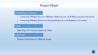
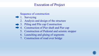
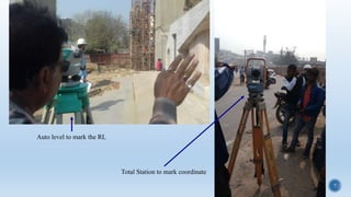
1
National Institute of Technology Patna
Presentation for Major Project (8CE195)
On
CONSTRUCTION OF FLYOVER IN PATNA
Presented by
Narayan Gupta(1403037)
Mahendra Kumar(1403089)
Akhilesh Rajpoot (1403016)
2
Construction of flyover
1. Connecting Mithapur flyover to Bhikhari Thakur flyover via R-Block junction (166 crores)
2. Connecting Mithapur flyover to Chiraiyatand flyover via karbigahiya (121 crores)
Client
Bihar Rajya Pul Nirman Nigam Ltd. Patna
Contractor
Rachna Construction Co. Bharuch, Gujrat
Project Detail
3
Introduction
1 2R-Block junction karbigahiya
4
What is flyover?
A bridge over another road
Allowing traffic without interruption
with its approaches on both side
Super structure
Substructure
Foundation
Girder
Pier Cap
Pier shaft
Pile cap
Pile
5
Execution of Project
Sequence of construction
1. Surveying
2. Analysis and design of the structure
3. Piling and Pile cap Construction
4. Construction of Pier shaft and Pier cap
5. Construction of Pedestal and seismic stopper
6. Launching and gluing of segments
7. Construction of road over bridge
6
SURVEYING (TOPOGRAPHICAL SURVEY)
Topography is used to locater and determine
the position of any point in both the horizontal
and vertical coordinates.
various maps are studied and then detailed is
done by Total station (TS) and layouts are
given on AutoCAD.
By using AutoCAD we can find the
coordinates(north, east) and reduce level of
any point.
Coordinates of any point is marked with the
help of Total station.
Reduce level (RL) is marked by using Auto
level.
Circular mark on ground with
nail to represent a particular
coordinate and RL
7
Auto level to mark the RL
Total Station to mark coordinate
8
Piling
Type of pile - Bored Cast in-situ concrete piles
Code of practice - (IS 2911-part 1-section 2:2010)
1- Point is located on ground to start the excavation.
2- Soil is excavated by auger at located point and
liner(length 2-3m) is inserted.
FOUNDATIONS: Foundations are the structures
which are constructed below existing ground level. It
sustains the loads coming from the sub structures and
superstructures. Bridges had to carry a big load so PILE
FOUNDATION are preferred
Auger
Liner
9
3- Flushing is done using bentonite slurry
and bentonite is also used for the
stabilization of bore hole and boring is done
upto desired depth (30m-34m).
Bentonite
Tank for mixing of bentonite and waterHydrometer
10
4- boring is done by RIG machine(MAIT) and Bucket.
Rig machine
Bucket
11
5- formation of cage
Dimension and Reinforcement Detail for pile
Cage
Cover block
12
6-Shifting of cage into borehole
13
7- Manner of concreting which shall be by use of tremie
Tremie pipe(dia 200mm)-
for flushing and concreting
TM
Concrete pouring from TM into tremie
through hopper
Insertion of tremie pipe
14
Pile cap
1-Excvation of Soil for pile cap
15
2- Chipping of extra unsound concrete of pile that is above cut off level
And PCC is done at cut off level (thickness of PCC-100mm)
16
Hexagonal Pile cap
Rectangular Pile cap
Scaffolding for reinforcement work of pile cap
17
Reinforcement For Hexagonal Pile capReinforcement of Rectangular Pile Cap
Reinforcement of Pile Cap (4 type)
18
Drawing and BBS of Pile Cap
19
Cleaning and
lubrication of formwork
Assembling of
formwork
With clear cover of
75mm
20
Location of pier shaft is marked using total station
Vertical bar of pier shaft are placed in to marked location
21
Pouring of concrete and compaction of concrete using immersion vibrator
Workability is checked by slump test before pouring and sample is collected for compressive strength
22
Shear key is made at construction joint
Unloading of formwork
Curing of pile cape
23
After 28 days of pile cap casting , the paint of epoxy coal
tar Is applied to the surface of pile cap to make the
surface impermeable
Instead of using paint, grade of concrete is increased to
M- 45
24
Pier Shaft
Drawing and detailing of pier shaft BBS of pier shaft
25
Pier Shaft
Assembly of reinforcement for first lift Cleaning and lubrication of formwork and it is applied
26
Pouring of concrete using pump and TM
Workability is checked before pouring and cubes are casted
for compressive strength
Vertical pipe is used to prevent the
segregation of concrete
27
Reinforcement is done for second lift
Formwork is placed using hydra and pouring is done
28
Pier Shaft Curing of pier shaft is done using jute bag (sprinkle method)
29
Pier Cap and Portal beam of rotary is under construction….
30
Test
1- sample of concrete is collected at the time of pouring.
workability is checked by slump test.
for compressive strength of concrete, cube are casted and sent to lab for testing
Slump cone
31
Pile load test
Routine test
As per 2911 (part 4):1985
It is carried out on a working
pile with a view to check
whether pile is capable of
taking the working load
assigned to it.
The number of tests may
generally be one-half percent
of the total number of piles
required.
In this test compression load
is applied to the pile top by
means of a hydraulic jack
against rolled steel joist and
suitable load frame capable of
providing reaction and the
settlement is recorded by dial
gauges.
Dial gauge
Hydraulic jack
Kentledge
Maximum allowable settlement is 12 mm
32
Pile Integrity test
Non destructive pile integrity test (PIT)
using low strain integrity test
As per IS 14893:2001
This test is performed for confirming the
integrity of pile upto full depth
33
Supervision
-Helmet, jacket and shoes
for all employs and worker
-Barricading, Instruction
board, light, reflector, safety
cone, flag
-safety belt is used if any
worker is at height more
than 2m from ground
Safety
34
Supervision
Quality control
• Quality of Concrete--- workability and strength
compaction of concrete using immersion vibrator (IS 3558:1983)
curing
• Steel --- reinforcement as per drawing and BBS, dia and length of bar, spacing of bar,
lap length, binding of bar, development length, coupler, clear cover.
• Other material --- lubricant, bentonite, coal tar epoxy, paint etc.
35
Concrete material
Pile M 35
PCC M 15
Pile cape M 40
Pier shaft M 50
Clear cover to the reinforcement shall be
a) Pile cape - 75mm
b) Pile - 75mm
c) Pier - 50/75mm
Minimum lap length
Pile = 54d
Pile cape = 51d( for bottom and side face reinforcement)
=78d (for top face reinforcement )
Pier = 44d
d- Diameter of smaller bar being lapped
Steel
TMT bar (Fe 500D)
36
Cutting and bending of steel at yard
Threading for rebar splicing mechanical coupler
Reinforcement Yard
37
Batching plant
for production
of concrete
Batching Plant
38
Testing machines at lab
39
Fabrication of formwork and staging
Fabrication unit
40
Machine and Tools
Trailer concrete pump
Backhoe loader
Transit mixture
Water tanker Crawler crane
41
Machine and Tools
Rig machine
Hydraulic crane
Immersion
needle
vibrator
Concrete
breaker
42
Machine and Tools
Tremie pipe Funnel
Bucket Auger
Liner
43
Conclusion
Flyover makes transportation very easy. It becomes very difficult task when there
is a project inside the city. R-block and Karbigahiya are the busiest route of
Patna. In construction of flyover, construction of foundation requires large area
that interrupt the already running traffic.
Some point what we learned at site.
• To analyze the drawing of project and to prepare the BBS from drawing.
• Calculation of required concrete, steel and other material
• Surveying for accuracy of position of different part
• Various site test to ensure the quality of construction
• Safety check for efficient work
• Management of running traffic with the help of local police
• Handling of existing structure like sewer, underground cables and statue.
• Maintenance of data for completed structure
44
References
1. IS 456:2000
2. IS 2911 (Part 1/Sec 2):2010
3. IS 2911 (part 4):1985
4. IS 14893:2001
5. IS 3558:1983
Code of practice for plain and reinforced concrete
Design and construction of pile foundations-code of practice (bored cast in-
situ concrete piles)
Codes of practice for design and construction of pile foundations – load
test on piles
Non-destructive integrity testing of piles (NDT)-guidelines
Code of practice for use of immersion vibrators for consolidating concrete
45
THANK YOU

Major Project ppt

  • 1.
    1 National Institute ofTechnology Patna Presentation for Major Project (8CE195) On CONSTRUCTION OF FLYOVER IN PATNA Presented by Narayan Gupta(1403037) Mahendra Kumar(1403089) Akhilesh Rajpoot (1403016)
  • 2.
    2 Construction of flyover 1.Connecting Mithapur flyover to Bhikhari Thakur flyover via R-Block junction (166 crores) 2. Connecting Mithapur flyover to Chiraiyatand flyover via karbigahiya (121 crores) Client Bihar Rajya Pul Nirman Nigam Ltd. Patna Contractor Rachna Construction Co. Bharuch, Gujrat Project Detail
  • 3.
  • 4.
    4 What is flyover? Abridge over another road Allowing traffic without interruption with its approaches on both side Super structure Substructure Foundation Girder Pier Cap Pier shaft Pile cap Pile
  • 5.
    5 Execution of Project Sequenceof construction 1. Surveying 2. Analysis and design of the structure 3. Piling and Pile cap Construction 4. Construction of Pier shaft and Pier cap 5. Construction of Pedestal and seismic stopper 6. Launching and gluing of segments 7. Construction of road over bridge
  • 6.
    6 SURVEYING (TOPOGRAPHICAL SURVEY) Topographyis used to locater and determine the position of any point in both the horizontal and vertical coordinates. various maps are studied and then detailed is done by Total station (TS) and layouts are given on AutoCAD. By using AutoCAD we can find the coordinates(north, east) and reduce level of any point. Coordinates of any point is marked with the help of Total station. Reduce level (RL) is marked by using Auto level. Circular mark on ground with nail to represent a particular coordinate and RL
  • 7.
    7 Auto level tomark the RL Total Station to mark coordinate
  • 8.
    8 Piling Type of pile- Bored Cast in-situ concrete piles Code of practice - (IS 2911-part 1-section 2:2010) 1- Point is located on ground to start the excavation. 2- Soil is excavated by auger at located point and liner(length 2-3m) is inserted. FOUNDATIONS: Foundations are the structures which are constructed below existing ground level. It sustains the loads coming from the sub structures and superstructures. Bridges had to carry a big load so PILE FOUNDATION are preferred Auger Liner
  • 9.
    9 3- Flushing isdone using bentonite slurry and bentonite is also used for the stabilization of bore hole and boring is done upto desired depth (30m-34m). Bentonite Tank for mixing of bentonite and waterHydrometer
  • 10.
    10 4- boring isdone by RIG machine(MAIT) and Bucket. Rig machine Bucket
  • 11.
    11 5- formation ofcage Dimension and Reinforcement Detail for pile Cage Cover block
  • 12.
    12 6-Shifting of cageinto borehole
  • 13.
    13 7- Manner ofconcreting which shall be by use of tremie Tremie pipe(dia 200mm)- for flushing and concreting TM Concrete pouring from TM into tremie through hopper Insertion of tremie pipe
  • 14.
    14 Pile cap 1-Excvation ofSoil for pile cap
  • 15.
    15 2- Chipping ofextra unsound concrete of pile that is above cut off level And PCC is done at cut off level (thickness of PCC-100mm)
  • 16.
    16 Hexagonal Pile cap RectangularPile cap Scaffolding for reinforcement work of pile cap
  • 17.
    17 Reinforcement For HexagonalPile capReinforcement of Rectangular Pile Cap Reinforcement of Pile Cap (4 type)
  • 18.
    18 Drawing and BBSof Pile Cap
  • 19.
    19 Cleaning and lubrication offormwork Assembling of formwork With clear cover of 75mm
  • 20.
    20 Location of piershaft is marked using total station Vertical bar of pier shaft are placed in to marked location
  • 21.
    21 Pouring of concreteand compaction of concrete using immersion vibrator Workability is checked by slump test before pouring and sample is collected for compressive strength
  • 22.
    22 Shear key ismade at construction joint Unloading of formwork Curing of pile cape
  • 23.
    23 After 28 daysof pile cap casting , the paint of epoxy coal tar Is applied to the surface of pile cap to make the surface impermeable Instead of using paint, grade of concrete is increased to M- 45
  • 24.
    24 Pier Shaft Drawing anddetailing of pier shaft BBS of pier shaft
  • 25.
    25 Pier Shaft Assembly ofreinforcement for first lift Cleaning and lubrication of formwork and it is applied
  • 26.
    26 Pouring of concreteusing pump and TM Workability is checked before pouring and cubes are casted for compressive strength Vertical pipe is used to prevent the segregation of concrete
  • 27.
    27 Reinforcement is donefor second lift Formwork is placed using hydra and pouring is done
  • 28.
    28 Pier Shaft Curingof pier shaft is done using jute bag (sprinkle method)
  • 29.
    29 Pier Cap andPortal beam of rotary is under construction….
  • 30.
    30 Test 1- sample ofconcrete is collected at the time of pouring. workability is checked by slump test. for compressive strength of concrete, cube are casted and sent to lab for testing Slump cone
  • 31.
    31 Pile load test Routinetest As per 2911 (part 4):1985 It is carried out on a working pile with a view to check whether pile is capable of taking the working load assigned to it. The number of tests may generally be one-half percent of the total number of piles required. In this test compression load is applied to the pile top by means of a hydraulic jack against rolled steel joist and suitable load frame capable of providing reaction and the settlement is recorded by dial gauges. Dial gauge Hydraulic jack Kentledge Maximum allowable settlement is 12 mm
  • 32.
    32 Pile Integrity test Nondestructive pile integrity test (PIT) using low strain integrity test As per IS 14893:2001 This test is performed for confirming the integrity of pile upto full depth
  • 33.
    33 Supervision -Helmet, jacket andshoes for all employs and worker -Barricading, Instruction board, light, reflector, safety cone, flag -safety belt is used if any worker is at height more than 2m from ground Safety
  • 34.
    34 Supervision Quality control • Qualityof Concrete--- workability and strength compaction of concrete using immersion vibrator (IS 3558:1983) curing • Steel --- reinforcement as per drawing and BBS, dia and length of bar, spacing of bar, lap length, binding of bar, development length, coupler, clear cover. • Other material --- lubricant, bentonite, coal tar epoxy, paint etc.
  • 35.
    35 Concrete material Pile M35 PCC M 15 Pile cape M 40 Pier shaft M 50 Clear cover to the reinforcement shall be a) Pile cape - 75mm b) Pile - 75mm c) Pier - 50/75mm Minimum lap length Pile = 54d Pile cape = 51d( for bottom and side face reinforcement) =78d (for top face reinforcement ) Pier = 44d d- Diameter of smaller bar being lapped Steel TMT bar (Fe 500D)
  • 36.
    36 Cutting and bendingof steel at yard Threading for rebar splicing mechanical coupler Reinforcement Yard
  • 37.
    37 Batching plant for production ofconcrete Batching Plant
  • 38.
  • 39.
    39 Fabrication of formworkand staging Fabrication unit
  • 40.
    40 Machine and Tools Trailerconcrete pump Backhoe loader Transit mixture Water tanker Crawler crane
  • 41.
    41 Machine and Tools Rigmachine Hydraulic crane Immersion needle vibrator Concrete breaker
  • 42.
    42 Machine and Tools Tremiepipe Funnel Bucket Auger Liner
  • 43.
    43 Conclusion Flyover makes transportationvery easy. It becomes very difficult task when there is a project inside the city. R-block and Karbigahiya are the busiest route of Patna. In construction of flyover, construction of foundation requires large area that interrupt the already running traffic. Some point what we learned at site. • To analyze the drawing of project and to prepare the BBS from drawing. • Calculation of required concrete, steel and other material • Surveying for accuracy of position of different part • Various site test to ensure the quality of construction • Safety check for efficient work • Management of running traffic with the help of local police • Handling of existing structure like sewer, underground cables and statue. • Maintenance of data for completed structure
  • 44.
    44 References 1. IS 456:2000 2.IS 2911 (Part 1/Sec 2):2010 3. IS 2911 (part 4):1985 4. IS 14893:2001 5. IS 3558:1983 Code of practice for plain and reinforced concrete Design and construction of pile foundations-code of practice (bored cast in- situ concrete piles) Codes of practice for design and construction of pile foundations – load test on piles Non-destructive integrity testing of piles (NDT)-guidelines Code of practice for use of immersion vibrators for consolidating concrete
  • 45.