Construction Methods & Sequence 3D Animation
•
20 likes•6,254 views

This presentation provides an overview of construction methods and sequencing using 3D animations and images. It aims to help stakeholders understand projects and engage site teams. The presentation covers general site facilities, temporary works like sheet pile walls, dewatering, traffic management, and more. Construction methods for various elements like diaphragm walls, vibro compaction, piling, and more are presented. The sequencing of activities like bridge construction, reinforced concrete works, and steel erection are also demonstrated.

Recommended
More Related Content
What's hot
What's hot (20)
Similar to Construction Methods & Sequence 3D Animation
Similar to Construction Methods & Sequence 3D Animation (20)
More from David H Moloney
More from David H Moloney (15)
Recently uploaded
Recently uploaded (20)
Construction Methods & Sequence 3D Animation
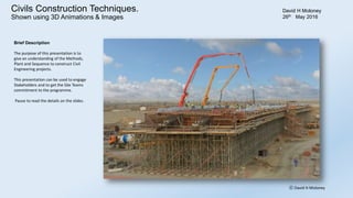
- 1. Construction Methods & Sequence Shown using 3D Animations & Images. David H Moloney 3rd June 2016 Brief Description The purpose of this presentation is to give an understanding of the Methods, Plant and Sequence to construct Civil Engineering projects. This presentation can be used to engage Stakeholders and to get the Site Teams commitment to the programme. Also can be used for Induction Training and as a way to capture and share knowledge. High in Educational Value and easily understood. Pause to read the details on the slides. ⓒ David H Moloney
- 4. Contractor’s Temporary Site Facilities ⓒ David H Moloney GeneralItems Brief Description Contractors Site facilities comprise: Offices, Canteens, Toilets, Drying Rooms, Stores, Plant Yard, generators and Workshops.
- 5. Contractor’s Temporary Site Facilities ⓒ David H Moloney GeneralItems
- 6. Contractor’s Camp for 8,000 persons ⓒ David H Moloney GeneralItems
- 7. Sheet Pile Temporary Shaft ⓒ David H Moloney GeneralItems Brief Description Sheet Pile Temporary shaft is used to enable an excavation for a deep structure. The construction sequence is: Install sheet-piles. Excavate and install bracing. Excavate to final level. Construct concrete structure. Backfill, remove bracing and sheet-piles
- 8. Sheet pile Temporary Shaft ⓒ David H Moloney GeneralItems 3D Animation to show Sequence
- 9. Dewatering ⓒ David H Moloney GeneralItems Brief Description Construction dewatering is the removal or drainage of groundwater and or surface / rain water usually by pumping to keep the works dry.
- 10. Dewatering ⓒ David H Moloney GeneralItems
- 11. Dewatering by Wellpoints ⓒ David H Moloney GeneralItems
- 12. Water Pollution Prevention ⓒ David H Moloney GeneralItems Brief Description Pumped and rain water that is contaminated with clay and silt needs to be treated prior to discharge from site. Settlement ponds and settlement tanks are two methods
- 13. Dewatering by Settlement Lagoon ⓒ David H Moloney GeneralItems
- 15. Traffic Management ⓒ David H Moloney GeneralItems Brief Description Traffic management plans are necessary when working on or beside roads
- 16. Traffic Management - Realign Motorway under new Bridges ⓒ David H Moloney GeneralItems
- 17. Traffic Management - Realign Motorway under new Bridges ⓒ David H Moloney GeneralItems
- 18. Traffic Management – Divert Live Traffic onto Realigned Carriageway ⓒ David H Moloney GeneralItems
- 19. Temporary Fence type 1 ⓒ David H Moloney GeneralItems Brief Description Examples of temporary security fences that are higher than the usual
- 20. Temporary Fence type 1 ⓒ David H Moloney GeneralItems
- 21. Temporary Fence type 2 ⓒ David H Moloney GeneralItems Brief Description Temporary fence on precast beam for airport.
- 22. Temporary Fence type 2 ⓒ David H Moloney GeneralItems
- 23. Site Hoarding examples ⓒ David H Moloney GeneralItems
- 24. FalseworkGeneralItems Brief Description Falsework to support Bridge deck formwork
- 25. Geotechnical
- 26. Diaphragm Wall Construction - Sequence, Plant & MethodsGeotechnical Brief Description A diaphragm wall is a reinforced concrete wall that is constructed underground insitu. A deep narrow trench is excavated in panels and filled with concrete. A mechanical grab or cutter suspended from a special tracked crane is used. Ground anchors or Bracing used to prevent wall collapsing inwards
- 27. Diaphragm Wall Construction - Sequence, Plant & Methods ⓒ David H Moloney Geotechnical
- 28. Vibro Compaction - Sequence, Plant & Methods ⓒ David H Moloney Geotechnical Brief Description Vibro compaction is used to compact granular ground to improve its load bearing capacity and reduces the seismic liquefaction potential. Used for the Palm Islands in Dubai. A vibrator suspended from a crane is used and inserted to a triangular grid pattern.
- 29. Vibro Compaction - Sequence, Plant & Methods ⓒ David H Moloney Geotechnical
- 30. Stone Columns ⓒ David H Moloney Geotechnical Brief Description Stone columns are used to improve the load bearing capacity of ground. Top feed vibrators suspended from an excavator or crane along with loading shovels are used. The stone columns are constructed to a triangular grid pattern.
- 31. Stone Columns ⓒ David H Moloney Geotechnical
- 32. Earthworks
- 33. Much Shifting Brief Description Muck Shifting is the process of moving large quantities of soil and rock. Earthworks
- 34. Excavate & Load, Cart, Tip & Return Brief Description Cycle Time for 7km haulage distance using an Excavator 45 tonne weight and Dumper with a 40 tonne capacity, the cycle time is 34 minutes Earthworks 7 minutes 14 minutes 3 minutes 14 minutes 7 km 7 km
- 47. Mass Haul DiagramEarthworks Brief Description Shows the quantities and location of excavation and fill quantities for motorway.
- 48. Rock - Excavability Brief Description The excavability of rock depends mainly on the rock strength and the layer thickness. This diagram shows excavation methods for rock of various strengths and thicknesses, with a free face. ⓒ David H Moloney Earthworks
- 51. Excavate with Roadheader Drill & Fit Rock Bolts Spray Mortar as Lining Excavators with Rock Breaker & Rock Rotary Cutter Roadheader MiningEarthworks Brief Description Mining. Rock breaking underground methods. Rock Bolts installation to strengthen the rock and eliminate rock falls. Spray mortar to line rock face.
- 52. Dredging & ReclamationEarthworks Brief Description Dredging is excavation under water. Reclamation is filling in water to make land.
- 54. Dredging & Reclamation PlantEarthworks
- 55. Diverting Existing Underground Utilities ⓒ David H Moloney Earthworks Brief Description Before digging establish the location and route of underground cables.
- 56. Concrete
- 57. Concrete Batching Plant David H Moloney ⓒ David H Moloney Brief Description Concrete batching plant comprises - concrete mixer, control cabin, silos for cement and fly ash, aggregate bins and conveyor belt system to feed the mixer. Also aggregate storage bays and water storage tanks. Concrete
- 58. Concrete Batching Plant ⓒ David H Moloney Concrete
- 59. Concrete Batching Plant ⓒ David H Moloney Concrete
- 60. Concrete Batching Plant – Computer Controlled ⓒ David H Moloney Concrete
- 61. Concrete Batching Plant David H Moloney ⓒ David H Moloney Brief Description . The mixing is computer controlled and has a dynamic screen display, showing the process. The material storage capacity is, to match two days concrete production. Concrete
- 62. Concrete Batching Plant on Barge for Marine Piles ⓒ David H Moloney Concrete
- 63. Quarry & Aggregate Production ⓒ David H Moloney Concrete Brief Description Quarry and Aggregate Production. Rock is blasted free from a quarry face and fragmented. The blasted rock is crushed and screened to produce different size ranges of aggregates
- 64. Quarry & Aggregate Production ⓒ David H Moloney Concrete
- 65. Quarry - Drilling Holes for Explosives ⓒ David H Moloney Concrete
- 66. Quarry - Placing Explosives in Holes ⓒ David H Moloney Concrete
- 67. Quarry - Blasting ⓒ David H Moloney Concrete
- 68. Aggregate Production ⓒ David H Moloney Concrete
- 69. Reinforcement Cutting & Bending Yard ⓒ David H Moloney Concrete Brief Description Reinforcement in 12 m lengths. Delivery in 3 ton Bundles
- 70. Reinforcement Cutting & Bending ⓒ David H Moloney Concrete
- 71. Reinforcement Cutting & Bending ⓒ David H Moloney Concrete
- 72. Reinforcement Cutting & Bending Yard David H Moloney ⓒ David H Moloney Reinforcement in 12 m lengths. Delivery in 3 ton Bundles Reinforcement cut to length by Shearing Machine Reinforcement Bent to Shape by Bending Machine Reinforcement that is cut and bent is Bundled for delivery to work site Concrete
- 73. Reinforced Wall Construction Sequence ⓒ David H Moloney Concrete Brief Description The sequence to construct a reinforced concrete wall is as follows: Tie the reinforcement. Erect stop-ends and the wall shutters. Pour and vibrate the concrete mix. Remove the shutters after the concrete has hardened. . Cycle Time Pour per Day
- 74. Reinforced Wall Construction Sequence ⓒ David H Moloney Concrete
- 75. Reinforced Structure Construction Sequence ⓒ David H Moloney Concrete Brief Description The general sequence to construct a reinforced concrete tank is as follows- 1. Construct the floor and wall panels in a hit and miss pattern. 2. Construct the floor and wall corners and T shape panels. 3. Construct the roof working outwards from the back.
- 76. Reinforced Structure Construction Sequence ⓒ David H Moloney Concrete
- 77. Reinforced Construction Tank, Construction Sequence David H Moloney ⓒ David H Moloney Concrete
- 78. Bridge & Post-tensioning Concrete Brief Description The sequence to post-tension a bridge deck is as follows; Fix the ducts and anchorages. Install the stressing strand. Concrete the deck. Stress the strands and lock at anchorages. Grout the ducts.
- 84. Bridge Post Tensioning Deck – Install Strand Concrete
- 85. Bridge Post Tensioning Deck Concrete
- 86. Bridge Construction Sequence David H Moloney ⓒ David H Moloney Concrete
- 87. Bridge Construction Stages, Images & Timeline Concrete
- 88. Bridge Construction Stages, Images & Timeline Concrete
- 89. Bridge Construction Stages, Images & Timeline Concrete
- 90. Bridge Construction Stages, Images & Timeline Concrete
- 91. Bridge Construction Stages, Images & Timeline Concrete
- 92. Bridge Construction Stages, Images & Timeline Concrete
- 93. Bridge Construction Stages, Images & Timeline Concrete
- 94. Bridge Construction Stages, Images & Timeline Concrete
- 95. Bridge Construction Stages, Images & Timeline Concrete
- 96. Bridge Construction Stages, Images & Timeline Concrete
- 97. Bridge Construction Stages, Images & Timeline Concrete
- 98. Viaduct Concrete Brief Description Shown is the construction of a light rail viaduct where an overhead gantry was used to lift and place the precast concrete viaduct segments.
- 99. Viaduct Concrete
- 100. Viaduct Concrete
- 101. Viaduct Concrete
- 102. Viaduct Concrete
- 103. Quay Wall Construction Concrete Brief Description The quay wall is 24 metres high and 2,250 metres long. The precast blocks weight up to 180 tonnes. The coping blocks are cast insitu.
- 105. Precast Quay Wall Blocks Concrete Brief Description A precast yard for casting, storage and loading the quay blocks onto barges. Cycles time to lift blocks of their casting pads is 4 days
- 106. Precast Quay Wall Blocks Concrete
- 107. Breakwater Sea Armour Placing Concrete Brief Description Shown is the sequence, plant and methods to construct a breakwater
- 108. Breakwater Sea Armour Placing Concrete
- 109. Precast Sea Armour Concrete Brief Description Shown is a precast yard to manufacture concrete precast sea armour
- 111. Tower Construction Concrete Brief Description Air Traffic Control Tower constructed using a jump-up shutter system.
- 112. Tower Construction Climbing Shutter Concrete Cycle Time 3 Days
- 113. Culvert Construction Concrete Brief Description Sequence to construct culvert with head walls.
- 115. Pipework
- 116. Onshore Gas Pipeline Construction Sequence Gas Processing Facility Pipework Brief Description Sequence, methods and plant to construct a gas / oil pipeline across country.
- 117. Onshore Gas Pipeline Construction Sequence Pipework
- 118. Pipe-jacking Pipework Brief Description Method for pipe-jacking The pipes are assembled in the access shaft and are pushed using a hydraulic jack..
- 120. Horizontal Directional Drilling Pipework Brief Description Horizontal Directional Drilling under a taxiway. Process 1. A pilot hole id drilled to the designed profile 2. A reamer is pulled back through the hole to enlarge it 3. A pipe string is pulled into the hole.
- 122. Cable Laying Pipework Brief Description 132 kVa Cable laying .
- 126. Cable Laying ⓒ David H Moloney Cable Drum Stand Cable pulled on rollers Cable Winch Cable Drum Unloading Cable on rollers Cable Testing prior to Backfilling Miscellaneous
- 127. Pipe Spools Fabrication Pipework Brief Description Spools are fabricated from pipes and fittings .
- 128. Spool Fabrication on site Pipework
- 129. Pipe Spool Fabrication Workshop Pipework
- 130. Spool Fabrication - Pipe Rolling & Cutting Table Pipework
- 131. Spool Fabrication Spool Rolling Pipework W. Soule & Company USA
- 132. Spool Fabrication - Automatic Welding with Pipe Rolling Pipework W. Soule & Company USA
- 133. Post Weld Heat Treatment Non Destructive Testing Cut Bevel Fit-up Weld NDT PWHT Blasting Painting Spool Fabrication Steps Pipework
- 134. Spool Fabrication Examples of Application Pipework Expansion Loop on Piperack Slug Catcher
- 135. Structural Steel & Miscellaneous
- 136. Steel Building Multi-storey ⓒ David H Moloney StructuralSteel Brief Description Sequence to erect a structural steel multi storey building.
- 137. Steel Building Multi-storey ⓒ David H Moloney StructuralSteel
- 138. Structural Steel Building Multi Storey ⓒ David H Moloney Step 1 Set-out Grid Lines Step 2 Holding Down Bolts Step 3 Erect 1st level use core for stability Step 4 Complete 1st Level Step 5 Erect following Levels Step 6 Plumb & Align Structure 3D images to show Construction Sequence. StructuralSteel
- 139. Steel Building Single Storey ⓒ David H Moloney StructuralSteel Brief Description Sequence to erect a structural steel single storey portal building.
- 140. Steel Building Single Storey ⓒ David H Moloney StructuralSteel
- 141. Structural Steel Building Single Storey 3D images to show Construction Sequence. ⓒ David H Moloney Step 1 Set-out Grid Lines Step 2 Holding Down Bolts Step 3 Erect 1st Bay Step 4 Erect 2nd Bay Step 5 Erect following Bays StructuralSteel
- 142. Steel Storage Tank ⓒ David H Moloney StructuralSteel Brief Description Sequence and methods to construct a steel circular tank.
- 143. Steel Storage Tank ⓒ David H Moloney StructuralSteel
- 144. Steel Circular Storage Tank – Construction ⓒ David H Moloney StructuralSteel
- 145. Pipe Rack ⓒ David H Moloney StructuralSteel Brief Description Sequence, methods and plant to construct a steel pipe rack that carriers the pipework and cables between the different processes in a gas / oil refinery.
- 146. Pipe Rack ⓒ David H Moloney StructuralSteel
- 147. Airport Roof Truss ⓒ David H Moloney StructuralSteel Brief Description Roof Truss 190 tonne in weight. Sections welded together on trestles and the truss is lifted into position.
- 148. Airport Roof Truss StructuralSteel Roof Truss Sections Roof Truss Sections assembled on trestles Trusses weigh 190 tonnes Crane Demag CC 8800
- 151. Piling
- 152. Piling Construction - Plant & Methods Brief Description Piling Plant, Equipment and Material; Crawler Crane, Piling Hammer, Temporary Casing, Piling Rig, Concrete Pump, Concrete Mixer Trucks, Tremie Pipe and Reinforcement Cage Piling
- 153. Piling Construction - Plant, Methods & SequencePiling
- 154. Piling Construction - Plant & MethodsPiling
- 155. Piling Construction - Vertical PilesPiling
- 156. Piling Construction - Raking PilesPiling
- 157. Secant Pile Wall Construction - Sequence, Plant & Methods ⓒ David H Moloney Piling Brief Description Sequence, methods and plant to construct a secant pile underground wall. Ground anchors or Bracing used to prevent wall collapsing inwardsGround anchors Bracing
- 158. Secant Pile Construction - Sequence, Plant & Methods ⓒ David H Moloney Piling
- 159. Pile Load Test ⓒ David H Moloney Piling Brief Description A jack is used to load the pile in steps and gauges measure any settlement.
- 160. Pile Load Test ⓒ David H Moloney Piling
- 161. Roads & Pavings
- 162. Asphalt Batching Yard Roads&Pavings Brief Description Asphalt Batching Yard .
- 166. Road Construction Brief Description Sequence, methods and plant to construct a motorway on a high embankment Roads&Pavings
- 169. Runway Asphalt Pavement Roads&Pavings Brief Description Sequence, plant and methods to construct a runway
- 173. Runway Asphalt Pavement - Marking Roads&Pavings
- 175. Asphalt Pavement - 4 Pavers in Echelon Roads&Pavings Brief Description 4 pavers used to minimise lengths of cold joints
- 176. Asphalt Pavement - 4 Pavers in Echelon Roads&Pavings
- 177. Concrete Slipform Paving Roads&Pavings Brief Description Slipform Airport Concrete paving. Slipform Concrete Paver Spreader Texturing & Curing
- 178. Concrete Slipform Paving – Texturing Machine Roads&Pavings
- 179. Concrete Slipform Paving - Slipform Machine Roads&Pavings
- 180. Concrete Slipform Paving – Placer / Spreader Machine Roads&Pavings
- 182. Concrete Slipform Paving – Drilling holes for dowels Roads&Pavings
- 183. Concrete Slipform Paving – Drilling holes for dowels Roads&Pavings
- 185. Tunnels
- 186. Tunnels Tunnels Brief Description 3D animation showing underground station and twin tunnels.
- 187. Tunnels Tunnels
- 188. Tunnels Tunnels
- 189. Tunnel Boring Machine (TBM) Cutting Head Rotates Excavated material removed by conveyor belt Lifting muck to surface with skip Placing Concrete Segments Tunnels Brief Description Tunnelling construction methods
- 190. Start Graphic Programme - Timeline & 3D Schematic Tunnel Profile
- 191. Tunnel Precast Segments Brief Description Process to precast tunnel segments. Cycle Time Daily Tunnels
- 193. Micro Tunnelling Brief Description Micro tunnelling is used to dig small tunnels where a tunnelling boring machine is controlled from a cabin at ground level Tunnels
- 195. Micro Tunnelling Sequence David H Moloney ⓒ David H Moloney Tunnels
- 196. Miscellaneous Works
- 197. Fencing Miscellaneous Brief Description Fencing. Sequence of construction; 1. Clear and grade the ground. 2. Fix corner and straining posts. 3. Fix intermediate posts. 4. Fix line wire, chain-link and razor wire. 5. Construct concrete ground beam
- 202. Cranes Lift Miscellaneous Brief Description Lifting a large column / vessel from the horizontal and rotate into the vertical using two cranes.
- 204. Gas Processing Facility Erect Flares / Columns & Vessels - 3D Simulation Miscellaneous
- 205. Climbing Tower Cranes Miscellaneous Brief Description A climbing tower crane lifts itself up using a climbing attachment with hydraulic jacks that surrounds the mast. The climbing attachment lifts itself up off the erected mast and inserts a new mast section.
- 208. Airplane Wingtip Clearance Miscellaneous Brief Description Regulation distances shown for wingtip clearance.
- 210. Taxiway Reconstruction Airside Miscellaneous Brief Description Regulations regarding working adjacent to a live runway.
- 214. Airfield Ground Lights Miscellaneous Jig to Level Pot
- 218. ILS Localiser Antenna & Approach Lights Miscellaneous
- 221. ILS Glide Path Antenna Miscellaneous
- 222. Progress Monitoring & Administration
- 223. Progress Monitoring & Reporting - Dashboard ⓒ David H Moloney Brief Description Dashboard is a single page, graphical representation of current progress and historical trends
- 224. Histogram Charts for Resources & Outputs Manpower per Discipline Concrete per Location Man-hours for each month of the Project Quantity for each month of the Project ⓒ David H Moloney Brief Description Histograms shows resources etc. for each month of a project.
- 225. Plant & Equipment List & Worker’s Job Titles ⓒ David H Moloney
- 226. Daily Work Record Brief Description Daily Work Records showing the allocation of resources, materials and work activities carried out daily.
- 227. Organogram Brief Description Shown are the line and lateral relationships between the various team members and their relative position in the site organisation.
- 228. Staff Directory Brief Description List of staff and their contact details
- 229. Time Chainage Diagram Brief Description The chart has two axis: one for time and the other for location A legend explains meaning of the colours, symbols and line types Legend
- 230. Production by David H Moloney My YouTube Channel link: https://www.youtube.com/channel/UCeJR9J7svhBd-C0ZoAH2fhQ