1. This document provides notes and specifications for the construction of a road over bridge (ROB) over railway tracks, including general notes, specification and design notes, and reference notes.
2. Key requirements include obtaining CRS sanction prior to work, maintaining minimum vertical clearances over tracks, providing crash barriers and guard rails, and designing the bridge to withstand specified loadings.
3. The road authority must enter an agreement with Railways and submit design drawings and completion drawings for approval before and after construction, and load test the bridge after completion.
What are methods of steel structure designnajeeb muhamed
There are three different methods for design of steel structure, i.e. simple design, continuous design and semi-continuous steel design.
Joints in structures have been assumed to behave as either pinned or rigid to render design calculations manageable.
In simple design the joints are idealised as perfect pins. Continuous design assumes that joints are rigid and that no relative rotation of connected members occurs whatever the applied moment.
The vast majority of designs carried out today make one of these two assumptions, but a more realistic alternative is now possible, which is known as semi-continuous design.
Geometric Design of Railways in India is explained. Design of horizontal curves, speed on curves, super-elevation, cant deficiency, transition curves etc. are included
The main outcome of this project is the construction sequence of HMR which primarily starts with excavation, erection of piers, launching girder process and assembling of segments. This project clearly gives a brief knowledge on how the post tensioning and pre stressing works are held at off site and onsite. This project enlightens about the safety requirements and measures taken during the pre-casting works and at on site works.
A. This Section includes removal of existing escalators and design, fabrication, and installation of heavy-duty escalators, designed specifically for transportation system usage, for the Washington Metropolitan Area Transit Authority (WMATA). This involves the installation of new escalators in the existing wellways at stations within the WMATA Metro Rail System. Work performed under this Section will provide new escalators complete and ready for use in compliance with all applicable Codes and the requirements of this Section.
Water scarcity is the lack of fresh water resources to meet the standard water demand. There are two type of water scarcity. One is physical. The other is economic water scarcity.
CFD Simulation of By-pass Flow in a HRSG module by R&R Consult.pptxR&R Consult
CFD analysis is incredibly effective at solving mysteries and improving the performance of complex systems!
Here's a great example: At a large natural gas-fired power plant, where they use waste heat to generate steam and energy, they were puzzled that their boiler wasn't producing as much steam as expected.
R&R and Tetra Engineering Group Inc. were asked to solve the issue with reduced steam production.
An inspection had shown that a significant amount of hot flue gas was bypassing the boiler tubes, where the heat was supposed to be transferred.
R&R Consult conducted a CFD analysis, which revealed that 6.3% of the flue gas was bypassing the boiler tubes without transferring heat. The analysis also showed that the flue gas was instead being directed along the sides of the boiler and between the modules that were supposed to capture the heat. This was the cause of the reduced performance.
Based on our results, Tetra Engineering installed covering plates to reduce the bypass flow. This improved the boiler's performance and increased electricity production.
It is always satisfying when we can help solve complex challenges like this. Do your systems also need a check-up or optimization? Give us a call!
Work done in cooperation with James Malloy and David Moelling from Tetra Engineering.
More examples of our work https://www.r-r-consult.dk/en/cases-en/
Welcome to WIPAC Monthly the magazine brought to you by the LinkedIn Group Water Industry Process Automation & Control.
In this month's edition, along with this month's industry news to celebrate the 13 years since the group was created we have articles including
A case study of the used of Advanced Process Control at the Wastewater Treatment works at Lleida in Spain
A look back on an article on smart wastewater networks in order to see how the industry has measured up in the interim around the adoption of Digital Transformation in the Water Industry.
NO1 Uk best vashikaran specialist in delhi vashikaran baba near me online vas...Amil Baba Dawood bangali
Contact with Dawood Bhai Just call on +92322-6382012 and we'll help you. We'll solve all your problems within 12 to 24 hours and with 101% guarantee and with astrology systematic. If you want to take any personal or professional advice then also you can call us on +92322-6382012 , ONLINE LOVE PROBLEM & Other all types of Daily Life Problem's.Then CALL or WHATSAPP us on +92322-6382012 and Get all these problems solutions here by Amil Baba DAWOOD BANGALI
#vashikaranspecialist #astrologer #palmistry #amliyaat #taweez #manpasandshadi #horoscope #spiritual #lovelife #lovespell #marriagespell#aamilbabainpakistan #amilbabainkarachi #powerfullblackmagicspell #kalajadumantarspecialist #realamilbaba #AmilbabainPakistan #astrologerincanada #astrologerindubai #lovespellsmaster #kalajaduspecialist #lovespellsthatwork #aamilbabainlahore#blackmagicformarriage #aamilbaba #kalajadu #kalailam #taweez #wazifaexpert #jadumantar #vashikaranspecialist #astrologer #palmistry #amliyaat #taweez #manpasandshadi #horoscope #spiritual #lovelife #lovespell #marriagespell#aamilbabainpakistan #amilbabainkarachi #powerfullblackmagicspell #kalajadumantarspecialist #realamilbaba #AmilbabainPakistan #astrologerincanada #astrologerindubai #lovespellsmaster #kalajaduspecialist #lovespellsthatwork #aamilbabainlahore #blackmagicforlove #blackmagicformarriage #aamilbaba #kalajadu #kalailam #taweez #wazifaexpert #jadumantar #vashikaranspecialist #astrologer #palmistry #amliyaat #taweez #manpasandshadi #horoscope #spiritual #lovelife #lovespell #marriagespell#aamilbabainpakistan #amilbabainkarachi #powerfullblackmagicspell #kalajadumantarspecialist #realamilbaba #AmilbabainPakistan #astrologerincanada #astrologerindubai #lovespellsmaster #kalajaduspecialist #lovespellsthatwork #aamilbabainlahore #Amilbabainuk #amilbabainspain #amilbabaindubai #Amilbabainnorway #amilbabainkrachi #amilbabainlahore #amilbabaingujranwalan #amilbabainislamabad
Hierarchical Digital Twin of a Naval Power SystemKerry Sado
A hierarchical digital twin of a Naval DC power system has been developed and experimentally verified. Similar to other state-of-the-art digital twins, this technology creates a digital replica of the physical system executed in real-time or faster, which can modify hardware controls. However, its advantage stems from distributing computational efforts by utilizing a hierarchical structure composed of lower-level digital twin blocks and a higher-level system digital twin. Each digital twin block is associated with a physical subsystem of the hardware and communicates with a singular system digital twin, which creates a system-level response. By extracting information from each level of the hierarchy, power system controls of the hardware were reconfigured autonomously. This hierarchical digital twin development offers several advantages over other digital twins, particularly in the field of naval power systems. The hierarchical structure allows for greater computational efficiency and scalability while the ability to autonomously reconfigure hardware controls offers increased flexibility and responsiveness. The hierarchical decomposition and models utilized were well aligned with the physical twin, as indicated by the maximum deviations between the developed digital twin hierarchy and the hardware.
Cosmetic shop management system project report.pdfKamal Acharya
Buying new cosmetic products is difficult. It can even be scary for those who have sensitive skin and are prone to skin trouble. The information needed to alleviate this problem is on the back of each product, but it's thought to interpret those ingredient lists unless you have a background in chemistry.
Instead of buying and hoping for the best, we can use data science to help us predict which products may be good fits for us. It includes various function programs to do the above mentioned tasks.
Data file handling has been effectively used in the program.
The automated cosmetic shop management system should deal with the automation of general workflow and administration process of the shop. The main processes of the system focus on customer's request where the system is able to search the most appropriate products and deliver it to the customers. It should help the employees to quickly identify the list of cosmetic product that have reached the minimum quantity and also keep a track of expired date for each cosmetic product. It should help the employees to find the rack number in which the product is placed.It is also Faster and more efficient way.
Overview of the fundamental roles in Hydropower generation and the components involved in wider Electrical Engineering.
This paper presents the design and construction of hydroelectric dams from the hydrologist’s survey of the valley before construction, all aspects and involved disciplines, fluid dynamics, structural engineering, generation and mains frequency regulation to the very transmission of power through the network in the United Kingdom.
Author: Robbie Edward Sayers
Collaborators and co editors: Charlie Sims and Connor Healey.
(C) 2024 Robbie E. Sayers
RAT: Retrieval Augmented Thoughts Elicit Context-Aware Reasoning in Long-Hori...
GADFORROB.pdf
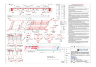
1. SANCTION OF CRS TO BE OBTAINED PRIOR TO EXECUTION OF THE WORK.
General Notes
1. Unless otherwise specified, all measurements are shown in mm and levels are shown in meters.
2. The foundation levels shown in the drawing are to be verified at site based on confirmatory subsoil investigation prior to commencement of
work.
3. Max pressure on the soil at foundation level is specified in concerned detailed drawings pertaining to foundations.
4. The bridge shall be designed to IRC class 'A' loading or 70R loading or 385T (S.V Loading) whichever gives worst effect for the given
carriageway width as per IRC standards.
5. Stair cases are to be provided on both sides of the ROB outside railway boundary to suit pedestrian traffic (wherever footpaths are provided).
6. 4.00m wide strip with polysulphide paint preferably in black colour shall be provided on the soffit of deck and footpath slabs over running
tracks.
7. Guard rails shall be provided on tracks below ROB.
8. No construction joint shall be allowed in concrete work unless it is specified in detailed drawings as per design considerations.
9. The details, type and dimensions of foundations, & sub-structure and super structure elements shown in the drawing are indicative and may
vary as per actual design and detailed drawings. However obligatory clearances mentioned in the drawings shall not be reduced under any
circumstances without prior approval of CBE.
10.High containment crash barrier of 1.80m height within Railway boundary and 1.50m height in approaches beyond Railway boundary for
minimum length of 90.00m above footpath level shall be provided as per IRC 5&6 guide lines.
11.The land boundaries indicated in the drawing here may not reflect the actual Railway boundary and reckoning actual land. The certified land
plan as available in HQ of divisional offices only is the final authority. The land boundaries shown in this plan cannot be of authority for this
purpose.
Specification and design related notes:
1. The grade of concrete for various RCC/Mass concrete works, & grade of steel for composite structures shall be in accordance with IRS
concrete bridge code 1997 & new I.S.456-2000 and IRC Codes & specifications etc.
2. Expansion joints shall be strip seal joints as per MORTH specifications. Confined POT Bearings shall mandatory be provided for spans
exceeding 30.0m.
3. Elastomeric/Pot-Ptfe Bearings shall be as per MORTH standards and specifications.
4. Protective coatings for reinforcement against corrosion should be provided as per latest correction slip of IRS concrete bridge code edition.
5. Drainage spouts shall be provided 2.00m away from the center line of existing / future track considering the traction / future traction and same
has to be ensured in the detailed drawings and by the Engineer-in-charge at site.
6. During construction a minimum clearance of 2575mm to be maintained between centre line of existing track to the face of Temporary
Arrangements Structure.
7. Variation of transverse slopes shall be maintained in deck/superstructure only. Under any circumstances, wearing coat thickness should not
exceed 80mm thick during execution and maintenance period. This shall be ensuring by Road authority under Railway supervision from time
to time”.
8. Bridge is to be designed assuming exposure condition as moderate.
9. Provision of clamps in the superstructure for supporting the traction wire to be made in communication with concerned authority.
Reference notes/ Drawings:
1. Wearing coat with uniform thickness, and misc. items such as drainage spouts with grating arrangements etc., shall be similar to MORTH
drawing No.SD/205. Location of drainage spouts shall invariably be shown in detailed drawings.
2. Expansion joints, Elastomeric & Confined POT/PTFE bearings shall be procured only from pre-qualified manufacturers of MORTH. Warranty
and maintenance conditions on these items have to be ensured as per MORTH guidelines/circulars issued from time to time.
3. For 36.0m composite super structure refer DRg. Nos: RDSO/B-10775, to 10775/12.
4. for 18.0m composite girder super structure refer drawing no. RDSO/B-11772 to RDSO/B-11772/12, RDSO/B-11776 series and CBS-0044
IMPORTANT NOTES:
1. A common bench mark should be established by Railways and Road Authority Engineers before starting the work.
2. Concerned Road Authority (NHAI) has to enter an MOU with south central Railway.
as per draft MOU vetted by PCE office before commencement of the work. PCE office will coordinate to finalize the draft copy of
MOU. ROB work in Railway portion shall be commenced accordingly as per terms and conditions of MOU. MOU shall be signed in triplicate.
Original shall be retained by PCE office. Duplicate and Triplicate copies shall be retained with NHAI and Devision.
3. Concerned Road Authority has to submit Completion Drawings of Detailed drawings & GAD and final design in original (drawings in cloth
tracing) duly signed by them and Railway Divisional officials after immediate completion of the work in accordance with para 911 of Indian
Railway Works Manual.
4. Load test has to be carried out in presence of NHAI & Railway Authorities immediately after completion of the superstructure considering the
provisions of IRC SP 51-2015 - Guide lines for load testing of Bridges.
5. All the records of Quality Assurance / Quality Control, testing of the materials and satisfactory completion of an activity shall be maintained at
site by the Contractor's Engineer and Supervising Engineers. On the basis of the records, Railways Engineers shall do stage wise clearance.
Without such stage clearance, the work in the next stage of construction shall be not allowed by the Railway Supervisor, unless proper system
of check and exercise is followed at the site.
6. CRS permission shall be obtained prior to commencement of work considering para 1202 {Clause-2(g)} of Indian Railway P.Way Manual.
7. Safety Pre-Cautions and Measures to be observed during execution of ROB shall be finalized by Vijayawada Division with the
concerned road authority before commencement of work as per Railway Board Directives communicated to Divisions vide letter no: W-
71/BR/Safety/General dated: 16.11.2009.
8. Narrow road over bridges having width of deck less than approaches, traffic safety measures on approaches to narrow road over bridges shall
be provided by concerned road authority as per MORTH letter No.RW/NH/33044/23/2007-S&R® Dated: 31-10-2008. Concerned Railway
Division has to ensure it.
9. Procedural guidelines of Annexure-II and Annexure-I etc. issued by Railway Board vide their letter No.2001/CE-I/Misc/NH/4 Pt.III dated:
28.06.2010 shall be ensured during submission of proposal and during execution etc.
10.The scope of Railway supervision is main span of 3x36.0 composite+1x18.0mts composite (RDSO standard span). And the piers over which
the main span is resting. The arrangement of approach spans beyond Railway boundary shall not be changed without prior permission of
Railways as approved in the drawing.
11.The substructure and foundation shall be designed by considering RDSO standard drawings bearing Drg. Nos RDSO/B-11772 to
RDSO/B-11772/12 for 18.0m.and RDSO/B-10775/R to RDSO/B-10775/12 for 36.0m.
12.Para 1851 to 1853, 1033, 1617 & 1618 etc. of Indian Railway Code for Engineering Department mutatis-mutandis will apply for these works
and Concerned Road Authority/Railway Division has to ensure it from time to time.
13.This approval is subjected deposition of way leave charges, land leave charges and other charges as per extant Railway norms.
14.(a) As per clause A-3 of Memorandum dt.10/11/14 entered between ministry of Railways and ministry of Transport and Highways. NHAI has
to develop instrumentation scheme. Accordingly, NHAI has to submit detailed instrumentation in monitoring system as part of design &
drawings before commencement of the work.
(b)NHAI shall do the instrumentation in the Railway super structure across the Railway bridge portion NHAI has to develop maintenance &
inspection manual to maintain the ROB from time to time. NHAI also has to develop instrumentation system of ROB. The same have to be
ratified by Railways. NHAI has to submit periodical reports of the instrumentation system of super structure and bearings from time to time
Annual basis or the period specified by the railway division whichever less is.
15.Design of bearing is dependent on time period and flexibility of substructure. Therefore, the design of bearing shall be considered as part of
substructure for which the seismic forces are computed by considering time period of whole structure.
16.The inspection of steel composite girders of ROB shall be done as per railway board letter no: 2016/54/CE-III/BR/RDSO/MISC. Date:
15/07/2019 (Composite girder)
17.As per Railway board Lr. No: 2015/CE-IV/ROB/78 Pt. Date:07/12/2020 if work was not started after approval of GAD, The GAD needs to be
revalidate after a reasonable period of 2 years to match the prevailing ground situation.
18.Inspection of steel girder for ROB'S shall be done by RDSO (both at workshop & site) as per railway board letter no.
2016/54/CE-III/BR/RDSO/MISE Date: 15/07/2019
19.Height gueges need to be provided at starting of approaches in case of bowstring arrangement.
20.Proposed RCL indicated will be tentative approaches including approach span shall not be taken until finalization of detailed design and
drawings including launching scheme of main span crossing over railway track with bowstring type superstructure (bowstring girder).
21. Fixing of any electrical or communications cable, ducts, lighting mast/polls, boards etc.,over the crash barrier/parapet in the railway portion of
the viaduct is not permitted without prior approval of railway division officials.
22.Necessary reposition has to be made by road authorities (NHAI/MORTH) for shifting of railway assets temporaing/permanenthy due to
construction of ROB to railways before and during execution of ROB work.
DESCRIPTION
0.065
RAIL TOP LVL. (EXIST. TRACK)
LEVELS
MIN. VERTICAL CLEARANCE 6.55M
WEARING COAT THK.
M
M
M
UNITS
PROPOSED FRL CALCULATIONS
CROSS FALL OR
CAMBER M 0.3825
97.220
DEPTH OF GIRDER INCLUDING
SLAB (18.0M / 36.0M) M 1.165/1.881
℄OF EXPANSION JOINT
℄OF EXPANSION JOINT
(80MM)
P3
P2
FINISHED ROAD LEVEL
A2
93.014
FOUNDATION BOTTOM LEVEL
P2
P1
TO CHITRAKOOT
HALF PLAN AT TOP
HALF PLAN AT BOTTOM
RE WALL
RE WALL
APPROACH
TO MOHANGANJ
SLAB
(SCALE 1:150)
TO CHITRAKOOT
SECTION ELEVATION (RAILWAY PORTION)
( SCALE 1:150)
36 M STANDARD GIRDER
AS PER RDSO SPAN
(RDSO/B-11775)
A1
106.100
94.068
RE WALL
RAILWAY
BOUNDARY
℄OF PIER
CHAINAGE 43+578.7
43+541.7
43+504.7 43+633.7
106.100 106.100 106.100
94.750 95.414
26.973
GROUND LVL.
1.
2.
3.
4.
G.L
G.L
RAILWAY
BOUNDARY
43+560
95.711
BORE
HOLE-1
BORE
HOLE-1
32000 53000
PILE CAP
TOP LVL.
PILE CAP CUT LVL.
5100
3600
750 750
DIVERTED
CANAL /DRAIN
G.L
FRL.103.328
℄OF BEARING
2.50 % SLOPE
PILE
Ø1200(TYP.)
RE WALL
℄OF EXPANSION JOINT
(80MM)
5100
3600 750
750
1500
2000
330
℄
O
F
E
X
IS
T
IN
G
T
R
A
C
K
53000 SQ 56771 SK
32000 SQ 3428 SK RAILWAY BOUNDARY
℄
F
U
T
U
R
E
T
R
A
C
K
PILE CAP
TOP LVL.
PILE CAP CUT LVL.
5100
3600 750
750
℄OF BEARING
℄OF BEARING
36700 SQ 39311 SK (OVERALL
LENGTH OF STEEL GIRDER)
37000 SQ 39632SK(C/C OF EJ.)
36000 SQ 38560 SK
2.50 % SLOPE
PILE Ø1200(TYP.)
RE WALL
5100
3600
750 750
36 M STANDARD GIRDER
AS PER RDSO SPAN
(RDSO/B-11775)
℄OF TRACK ℄FUTURE TRACK
℄FUTURE TRACK
7800 SQ 8355 SK
℄OF EXPANSION JOINT
℄OF EXPANSION JOINT
(80MM)
A1 P1
℄OF EXPANSION JOINT
(80MM)
9695 SQ 10385 SK
TO MOHANGANJ
5100
'1'
'2'
7
5
0
3
6
0
0
3
6
0
0
7
5
0
3
6
0
0
1
2
3
0
0
5100
5100 SQ
5463 SK
G.L
PILE CAP
TOP LVL.
PILE CAP CUT LVL.
5100
3600
750 750
℄OF BEARING
18700 SQ 20030 SK (OVERALL
LENGTH OF STEEL GIRDER)
19080 SQ 20437 SK(C/C OF EJ.)
18000 SQ 19281 SK C/C OF BRG.
EXISTING CANAL / DRAIN
RAILWAY BOUNDARY
EXISTING CANAL / DRAIN DIVERTED
22262 SQ 23846 SK 12540 SQ 13454 SK 33540 SQ 35926 SK 1460 SQ 1564 SK 16869
6550
(MIN.
VERTICAL
CLEARANCE)
20°
21°
'3'
RE WALL
BORE
HOLE-2
5100
5100
7
5
0
3
6
0
0
3
6
0
0
7
5
0
3
6
0
0
1
2
3
0
0
7
5
0
S
Q
8
0
3
S
K
3
6
0
0
S
Q
3
8
5
6
S
K
1
2
3
0
0
S
Q
1
3
1
7
5
S
K
BORE
HOLE-2
A2
2000
9695 SQ
10385 SK
7800 SQ
8355 SK
36700 SQ 39311 SK (OVERALL
LENGTH OF STEEL GIRDER)
37000 SQ 39632SK(C/C OF EJ.)
36000 SQ 38560 SK
36700 SQ 39311 SK (OVERALL
LENGTH OF STEEL GIRDER)
37000 SQ 39632SK(C/C OF EJ.)
36000 SQ 38560 SK
7800 SQ 8355 SK
36000 SQ 38560 SK 36000 SQ 38560 SK 36000 SQ 38560 SK 18000 SQ 19281 SK
3
6
0
0
S
Q
3
8
5
6
S
K
3
6
0
0
S
Q
3
8
5
6
S
K
7
5
0
S
Q
8
0
3
S
K
7
5
0
S
Q
8
0
3
S
K
3
6
0
0
S
Q
3
8
5
6
S
K
1
2
3
0
0
S
Q
1
3
1
7
5
S
K
3
6
0
0
S
Q
3
8
5
6
S
K
3
6
0
0
S
Q
3
8
5
6
S
K
7
5
0
S
Q
8
0
3
S
K
7
5
0
S
Q
8
0
3
S
K
3
6
0
0
S
Q
3
8
5
6
S
K
1
2
3
0
0
S
Q
1
3
1
7
5
S
K
3
6
0
0
S
Q
3
8
5
6
S
K
3
6
0
0
S
Q
3
8
5
6
S
K
7
5
0
S
Q
8
0
3
S
K
7
5
0
S
Q
8
0
3
S
K
3
6
0
0
S
Q
3
8
5
6
S
K
1
2
3
0
0
S
Q
1
3
1
7
5
S
K
3
6
0
0
S
Q
3
8
5
6
S
K
3
6
0
0
S
Q
3
8
5
6
S
K
7
5
0
S
Q
8
0
3
S
K
7800 SQ
8355 SK
9695 SQ
10385 SK
95.200
43+615.7
106.100
P3
94.137 94.188 95.180 94.068 95.501 96.052 96.440 93.121 93.003
RAILWAY BRIDGE 49
'3'
T
O
U
N
C
H
A
H
A
R
T
O
P
H
A
P
H
A
M
A
U
/
P
R
A
Y
A
G
R
A
J
℄
F
U
T
U
R
E
T
R
A
C
K
℄
F
U
T
U
R
E
T
R
A
C
K
℄
F
U
T
U
R
E
T
R
A
C
K
℄
E
X
IS
T
IN
G
T
R
A
C
K
9695 SQ 10385 SK
9695 SQ
10385 SK
7800 SQ
8355 SK
7800 SQ
8355 SK
9695 SQ
10385 SK
18 M STANDARD GIRDER
AS PER RDSO SPAN
(RDSO/B-11772)
RTL
43+515 43+525 43+550 43+570 43+590 43+600 43+610 43+525
43+620
97.220
(RECHANNELISED )
RE 26/13
RE
26/11
3
6
5
0
0
*^
5
8
7
0
0
^^
21
90
0
*^
*^ = DISTANCE OF OHE MAST FROM ROB EDGE ABOVE
^^ = DISTANCE OF OHE MAST TO OHE MAST
6
2
9
0
0
^^
54801.2
^^
48247.7
*^
6553.5
*^
7546.5
*^
5872.22
^^
24646.5*^
34075.7*^
CENTER LINE OF EXISTING TRACK
RE 26/12
ABRIVATION:-
F.R.L FINISHED ROAD LEVEL
LVL.
TYP.
CENTER LINE
LEVEL
TYPICAL
C
L
THK. THICK
C/C
G.L
CENTER TO CENTER
GROUND LEVEL
FDN. FOUNDING LEVEL
EXP. EXPANSION
BRG. BEARING
SYMM. SYMMETRICAL
SQ SQUARE DIMENSION
SK. SKEW DIMENSION
BH BORE HOLE
FEATURES
PROPOSED WORK RED
COLOUR
TO BE DISMANTLE
GREEN
BLUE
FUTURE
EXIST. RAILWAY TRACK BLACK
PROP. RAILWAY TRACK GREEN
300
1500
500 250 1500 10500
CARRIAGE WAY
500
250
2500 2500 2500 2500 2500
SHY DISTANCE
CRASH BARRIER
RAILING FOOT
PATH
15300 SQ 16389 SK
300
1500
500
250
1500
10500
CARRIAGE WAY
500 250
SHY DISTANCE
CRASH BARRIER RAILING
FOOT
PATH
15300 SQ 16389 SK
2500
2500
2500
2500
2500
750
3600
750
12300
FOUNDATION AS PER DESIGN
FND. LVL. FND. LVL.
(SCALE 1:120)
SECTION AT A-A (ABUTMENT)
15300
(SCALE 1:150)
750
750
1500
2500 1650 7000 2500
3600 3600
PILE TOP LVL.
PILE TOP LVL.
GROUND LVL.
AS PER HIGHWAY PROFILE
2500
1650
7000
1650
2500
REWALL
2.5% SLOPE 2.5% SLOPE
750
12300
FOUNDATION AS PER DESIGN
3600 3600 3600
1825 1825 1825 1825
ABUTMENT CAP PLAN
1650
1600SQ
1714SK 2500SQ
2678SK
1200SQ
1285SK
15300 SQ/16389 SK
℄
OF
BRG.
JACKING
LOCATION (TYP.)
℄
OF
EXP.JOINT
1800SQ
1928SK
2500SQ
2678SK
2500SQ
2678SK
2500SQ
2678SK
2500SQ
2678SK
1600SQ
1714SK
2500SQ
2678SK
1200SQ
1285SK
15300 SQ/16389 SK
2500SQ
2678SK
2500SQ
2678SK
2500SQ
2678SK
2500SQ
2678SK
GAD NEED TO BE REVALIDATED AFTER A REASONABLE PERIOD OF 2 YEARS TO MATCH THE PREVAILING GROUND SITUATION.
GAD NEED TO BE REVALIDATED AFTER A REASONABLE PERIOD OF 2 YEARS TO MATCH THE PREVAILING GROUND SITUATION.
# FRL SHALL BE DECIDED AS PER RTL MAINTAINING MIN. CLEARANCE OF 6.50M BETWEEN RTL & GIRDER BOTTOM LEVEL.
DEPTH
(M) STRATA
BH A1(R.L.97.100m)
DESCRIPTION
SILTY WITH
GRAVEL
SAND AND
GRAVELLY
CLAY WITH SAND
SILT WITH
GRAVEL
FINE SAND
AND SILT
DETAILS OF BORE HOLE
43+500
43+600
43+700
43+800
EXISTING BRIDGE NO. 49
CANAL TO BE RETAINED AT
ABUTMENT PIER LOCATION
PROPOSED ROB DRAIN
26.973
510
0
10951
510
0
123
00
(SCALE 1:50)
DETAIL-'2' 1631
250
1881
DEPTH
(M) STRATA
DESCRIPTION
SILTY WITH
GRAVEL
SILTY CLAY
SILTY CLAY WITH
GRAVEL
SILT SAND WITH
GRAVEL
SILTY CLAY
WITH GRAVEL
GRAVEL WITH
SILT
BH P3(R.L.97.100m)
300
1500500 250 1500 10500
CARRIAGE WAY
500
250
2500 2500 2500 2500 2500
SHY DISTANCE
CRASH BARRIER
RAILING FOOT
PATH
15300
300
1500
500
250
1500
10500
CARRIAGE WAY
500 250
SHY DISTANCE
CRASH BARRIER RAILING
FOOT
PATH
15300
2500
2500
2500
2500
2500
(SCALE 1:120)
15300
750
750
1500
2500 2150 2150 2500
GROUND LVL. GROUND LVL.
AS PER HIGHWAY PROFILE
2500
2150
2150
2500
2.5% SLOPE 2.5% SLOPE
6000 6000
(SCALE 1:150)
PIER CAP PLAN
℄
OF
BRG.
℄
OF
EXP.JOINT
2330SQ
2496SK
1600SQ
1714SK 2500SQ
2678SK
1200SQ
1285SK
2500SQ
2678SK
2500SQ
2678SK
2500SQ
2678SK
2500SQ
2678SK
750
3600
750 3600 3600 750
3600 3600 3600
SECTION AT B-B (PIER)
15300 SQ/16389 SK
1600SQ
1714SK
2500SQ
2678SK
1200SQ
1285SK
2500SQ
2678SK
2500SQ
2678SK
2500SQ
2678SK
2500SQ
2678SK
15300 SQ/16389 SK
PILE TOP LVL.
PILE TOP LVL.
330
1631
250
1881
2000
1650
(SCALE 1:50)
DETAIL-'1'
750
750
330
915
250
1165
2000
1650
(SCALE 1:50)
DETAIL-'4'
750
750
(SCALE 1:50)
DETAIL-'3'
915
250
1165
1631
250
1881
KEY PLAN
GAD FOR CONSTRUCTION OF 4-LANE GREEN FIELD HIGHWAY FROM Km 35.000
TO KM 49.155 (AUTARPUR TO SINGARAUR UPHAR) OF NH -731A AT RAILWAY KM
26KM 750M 26/12 TP.
Consultancy Services for Feasibility Study & Preparation of Detailed Project Report for
improvement & up-gradation of in principle & newly declared National Highways in the
state of Uttar pradesh. Package-II (i) Stretch from Near Pratapgarh(NH-31) - Jethwada -
Shrangvepur-Manjhanpur-Rajapur - Near Chitrakoot (NH-35) & Length -160.000Km
DWG NO: ARKI/MORT&H/UP-17358/NH-731A/ROB/GAD/101
NORTHERN RAILWAY
CLIENT:
AUTHORITY OF WORK
DATE: JUNE 2022 PAPER SIZE: A0
SCALE : AS SHOWN REVISION : R2
DIVISION: SECTION: PHAPHAMAU-UNCHAHAR
PROPOSED ID : NRLK00040
LUCKNOW
Arkitechno Consultants(I) Pvt.Ltd.
N3/91, I.R.C Village, Near Maharishi Public School,Nayapalli, Bhubaneswar- 751015.Odisha
Telephone :+91 674 2554 205; Fax:+91 674 2553689
DESIGN CONSULTANTS
DRG. NO.
DRAWING TITLE:
CHECKED BY: A.A
DRAWN BY : D.R
EE,UPPWD
NH-DIVISION-1
DRM
Sr. DEN / COORDINATION
Sr. DEE (TRD)
Sr. DSTE
Sr. DOM
Sr. DEN / 6
PRAYAGRAJ
NR
NR
NR
NR
NR
NR
ADRM
NR
THE FEASIBILITY OF PROPOSED PLAN IS BEING
CHECKED AT SITE AND FOUND CORRECT
SSE / WORKS / PRG SSE / P. WAY / PRG ADEN / PRG
FOR SITE FEASIBILITY STUDY :-
CBE
DY. CE / ROB