Downloaded 1,704 times


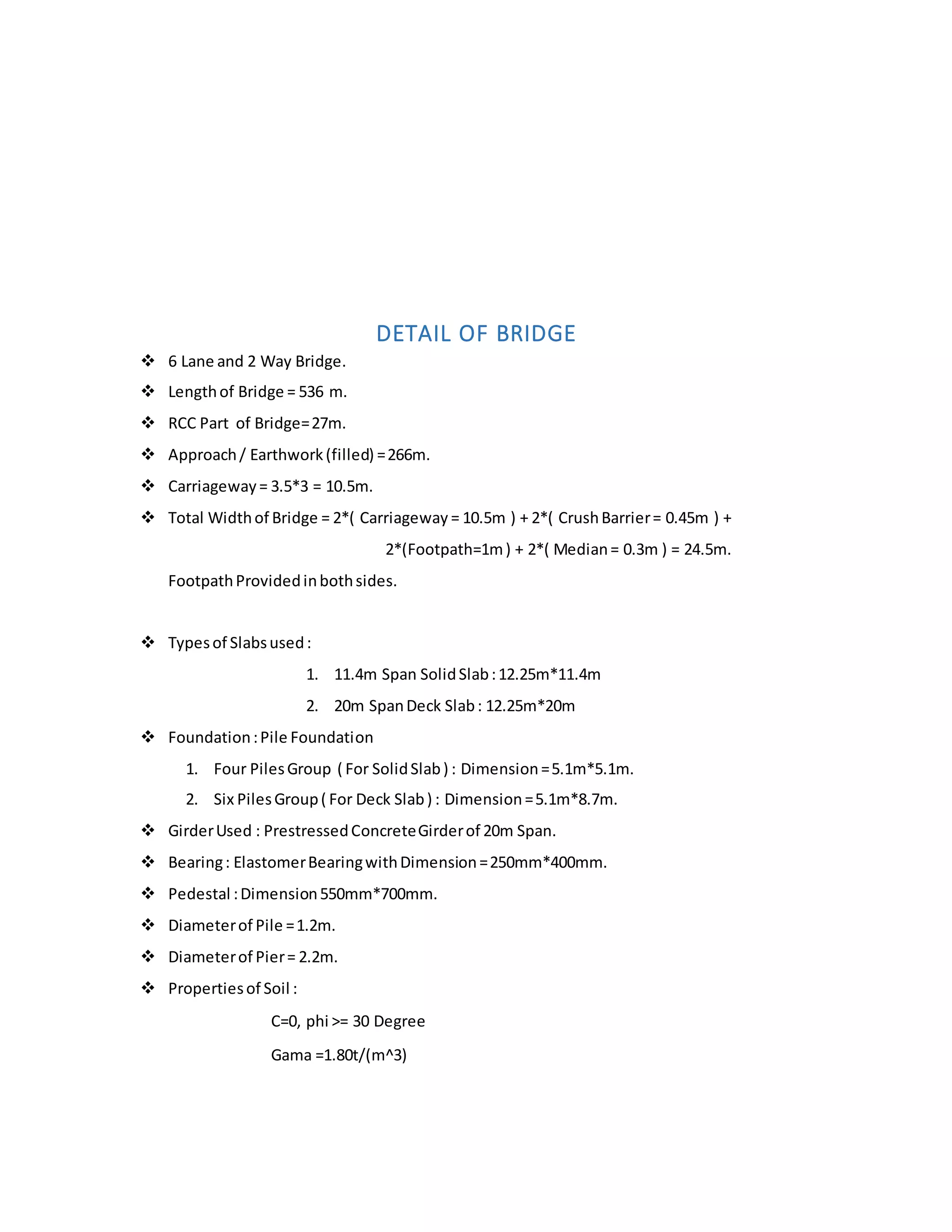

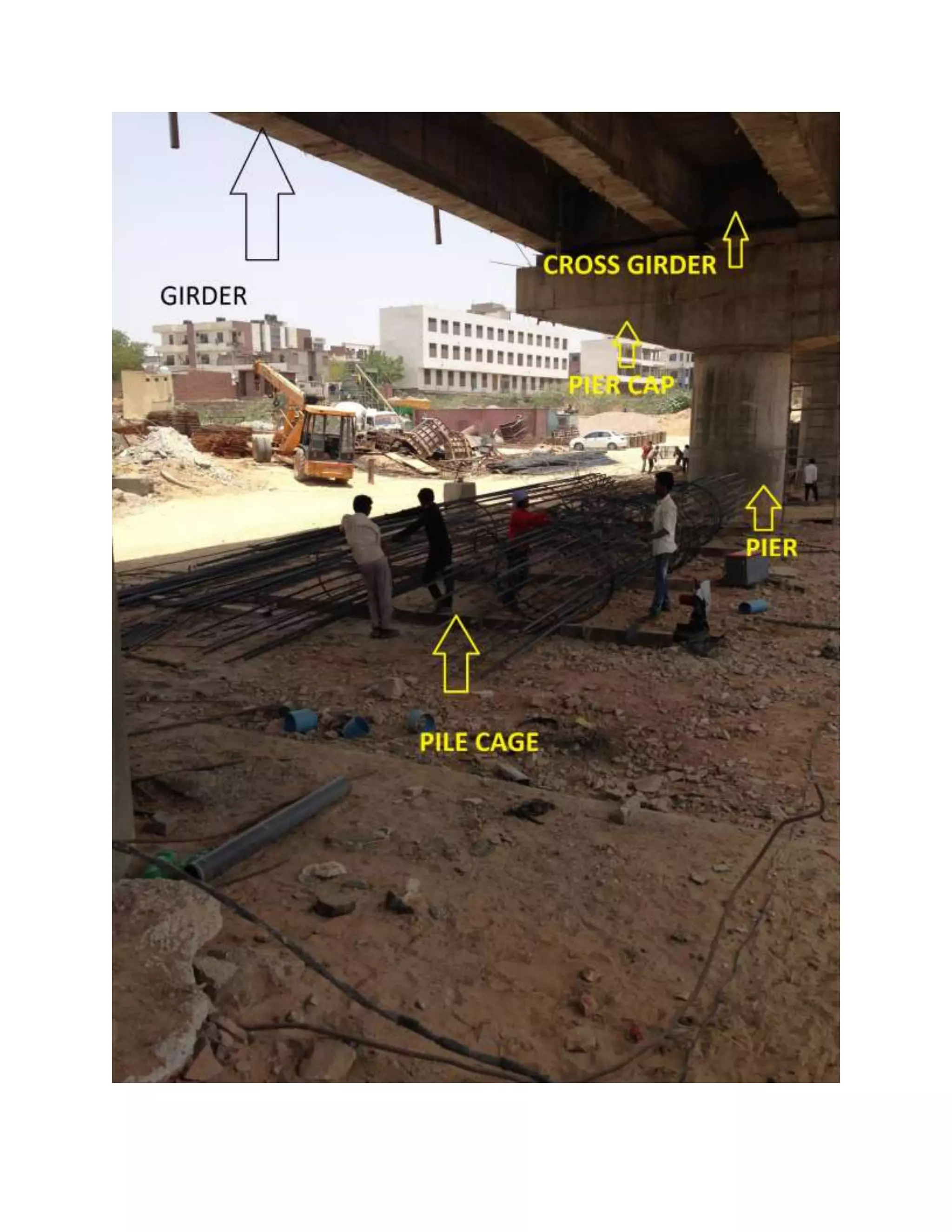
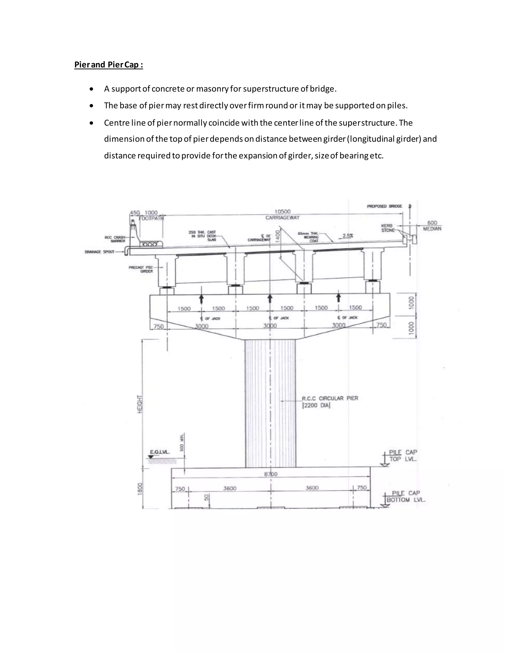
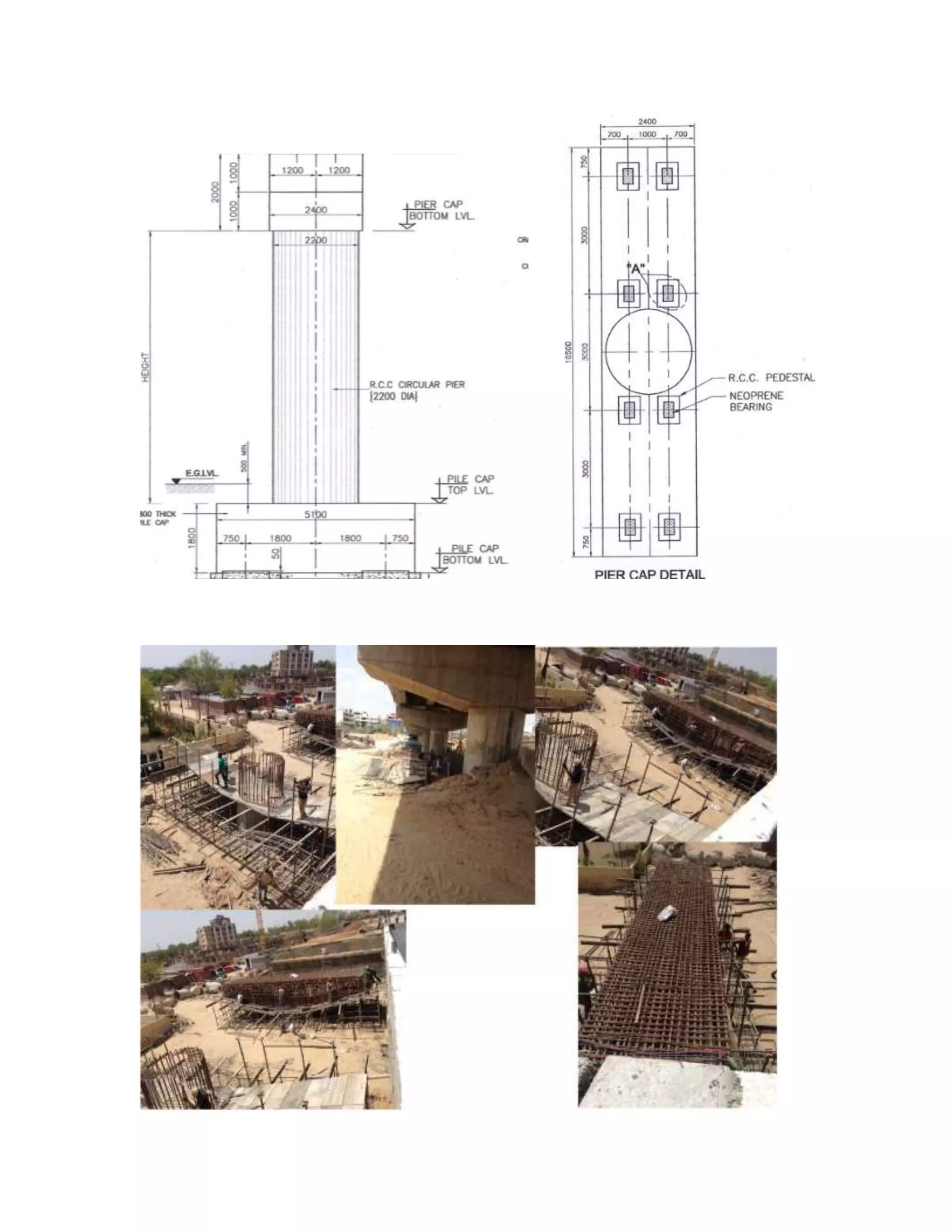
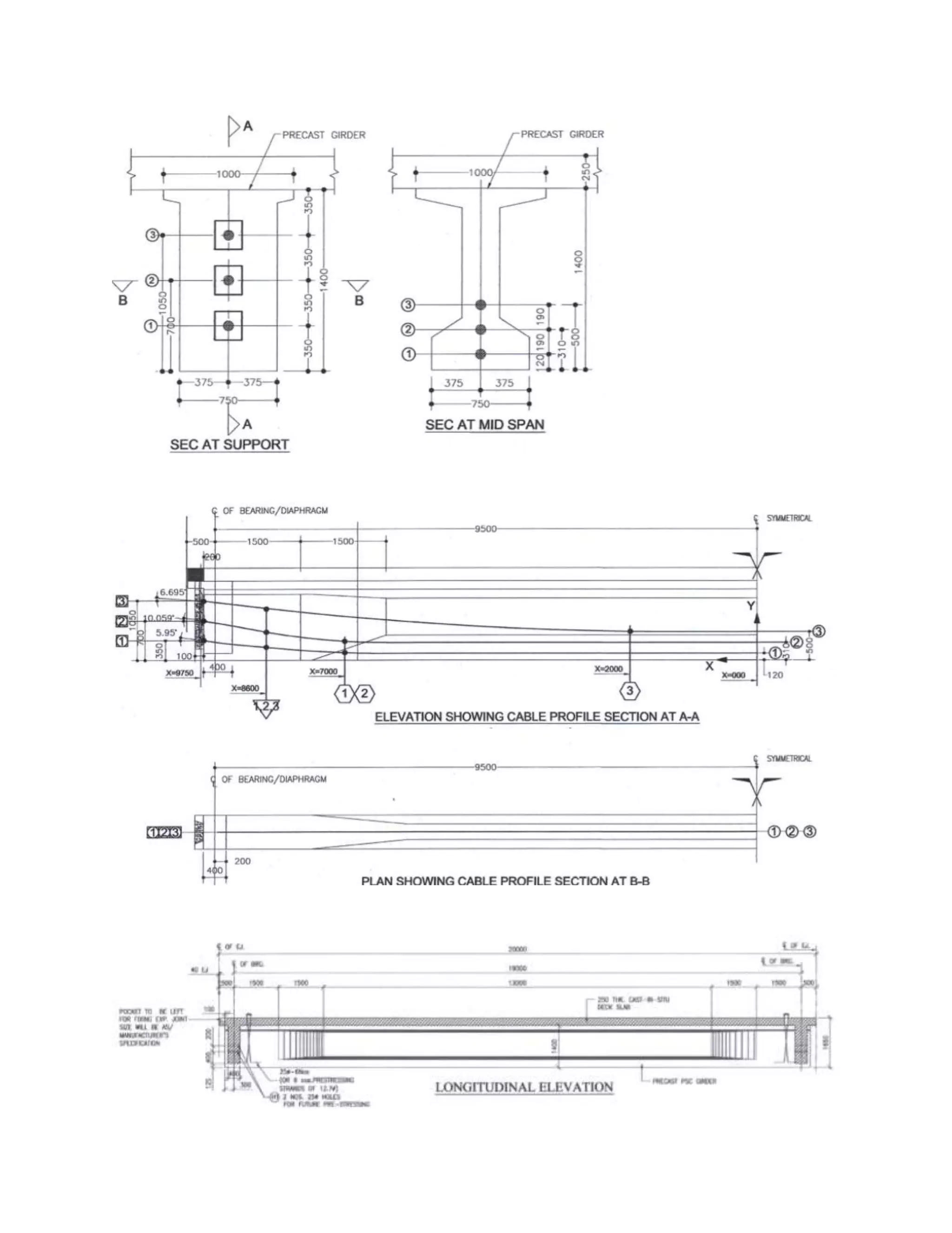
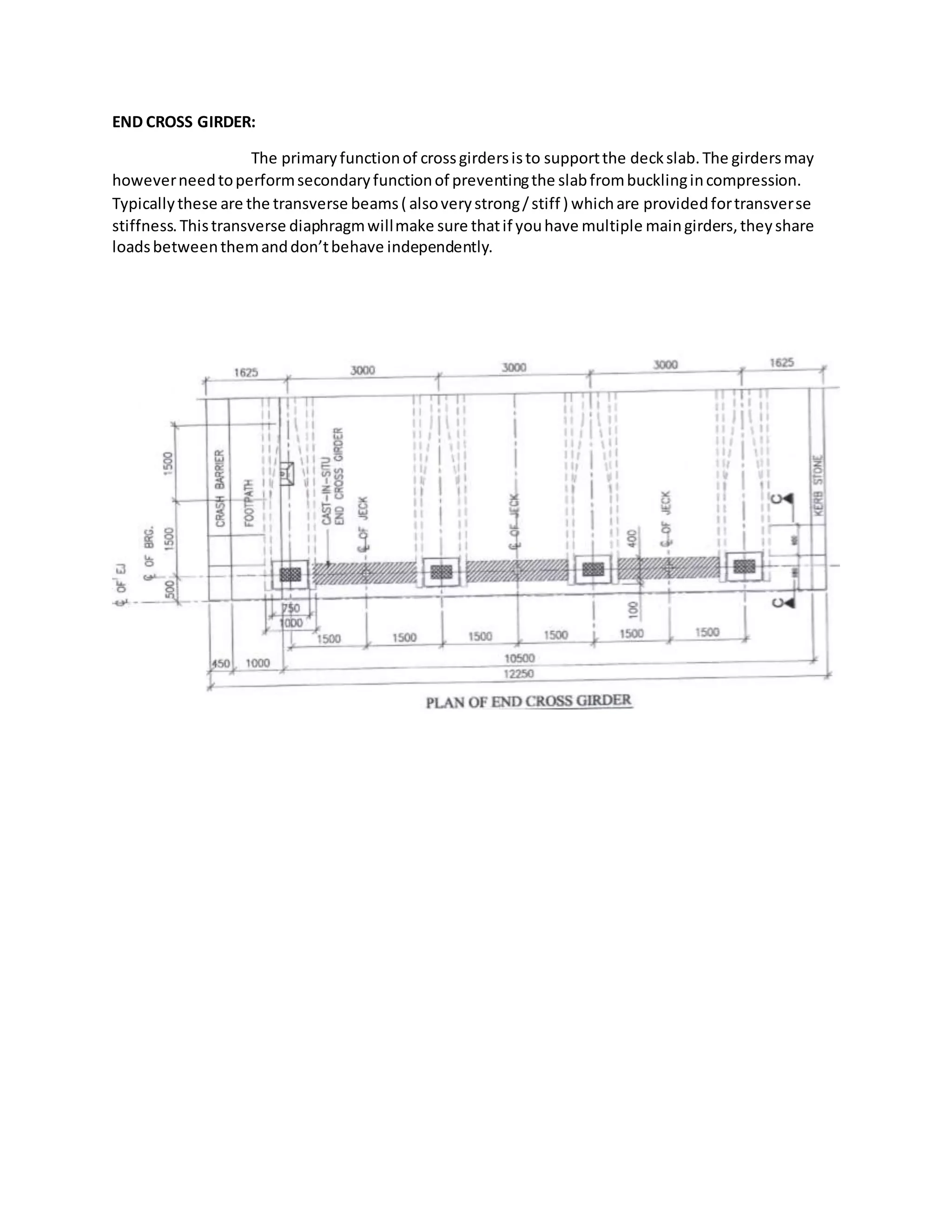
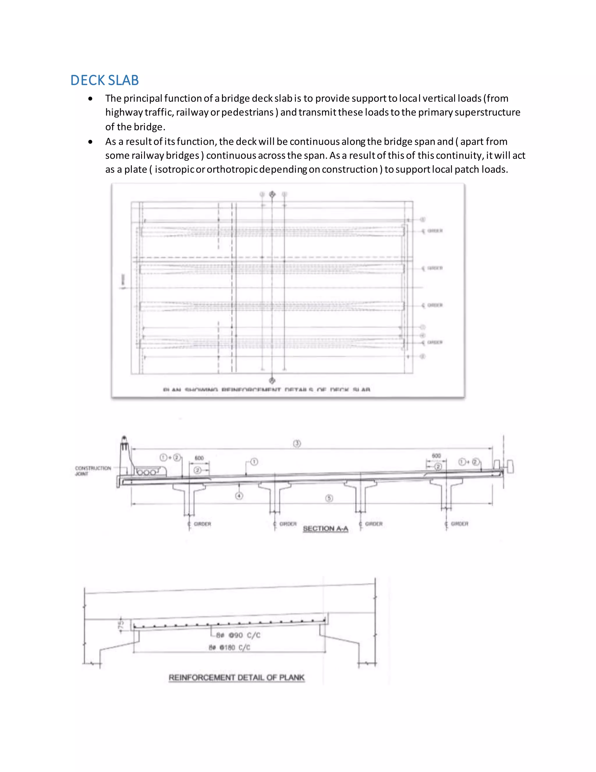
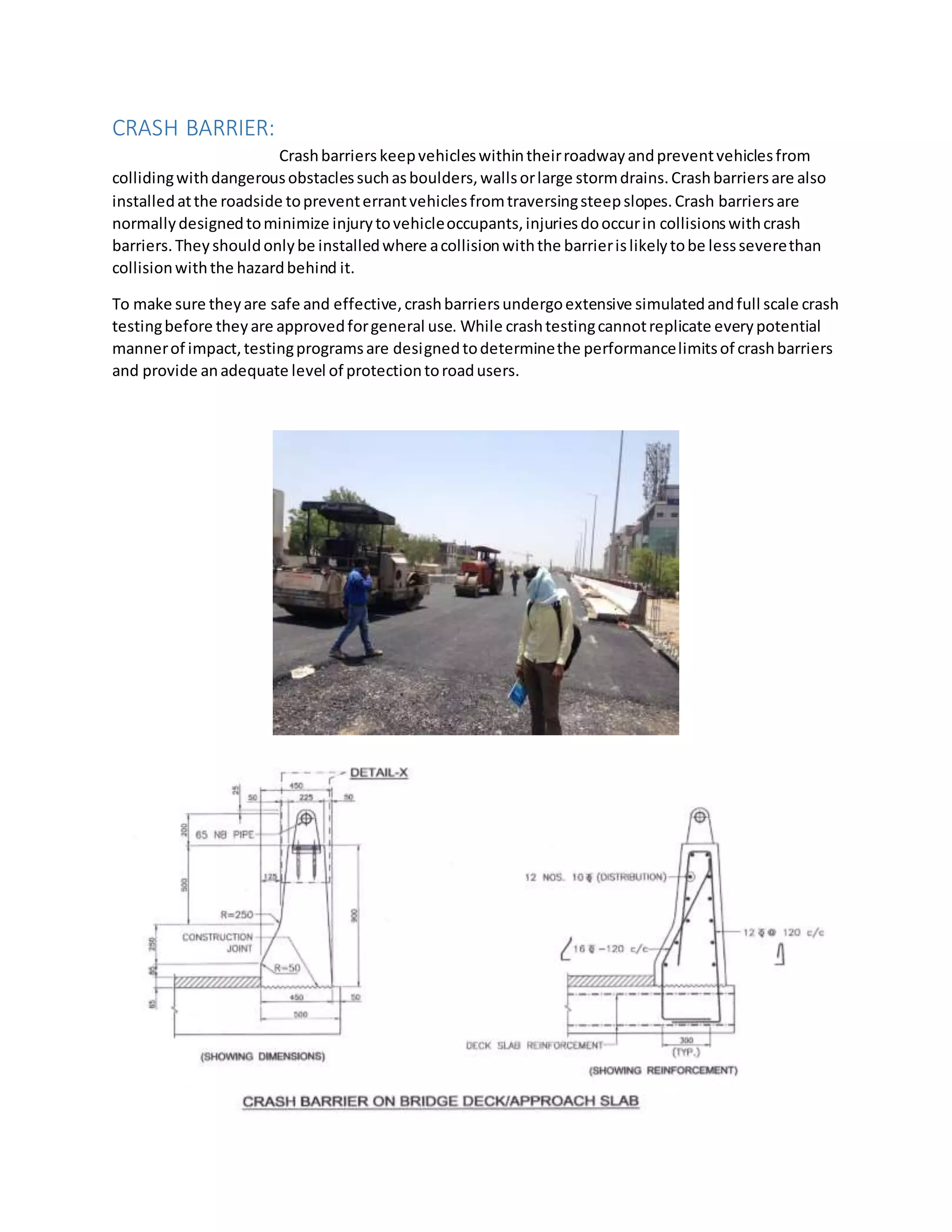


The document provides a training report for a bridge construction project in Jaipur, India during May-June 2016. It summarizes the key components of the bridge, including pile foundations, substructures like piers and pedestals, and superstructures such as prestressed concrete girders and deck slabs. The training helped the author gain practical knowledge of bridge construction techniques and management that supplemented their theoretical classroom learning.


