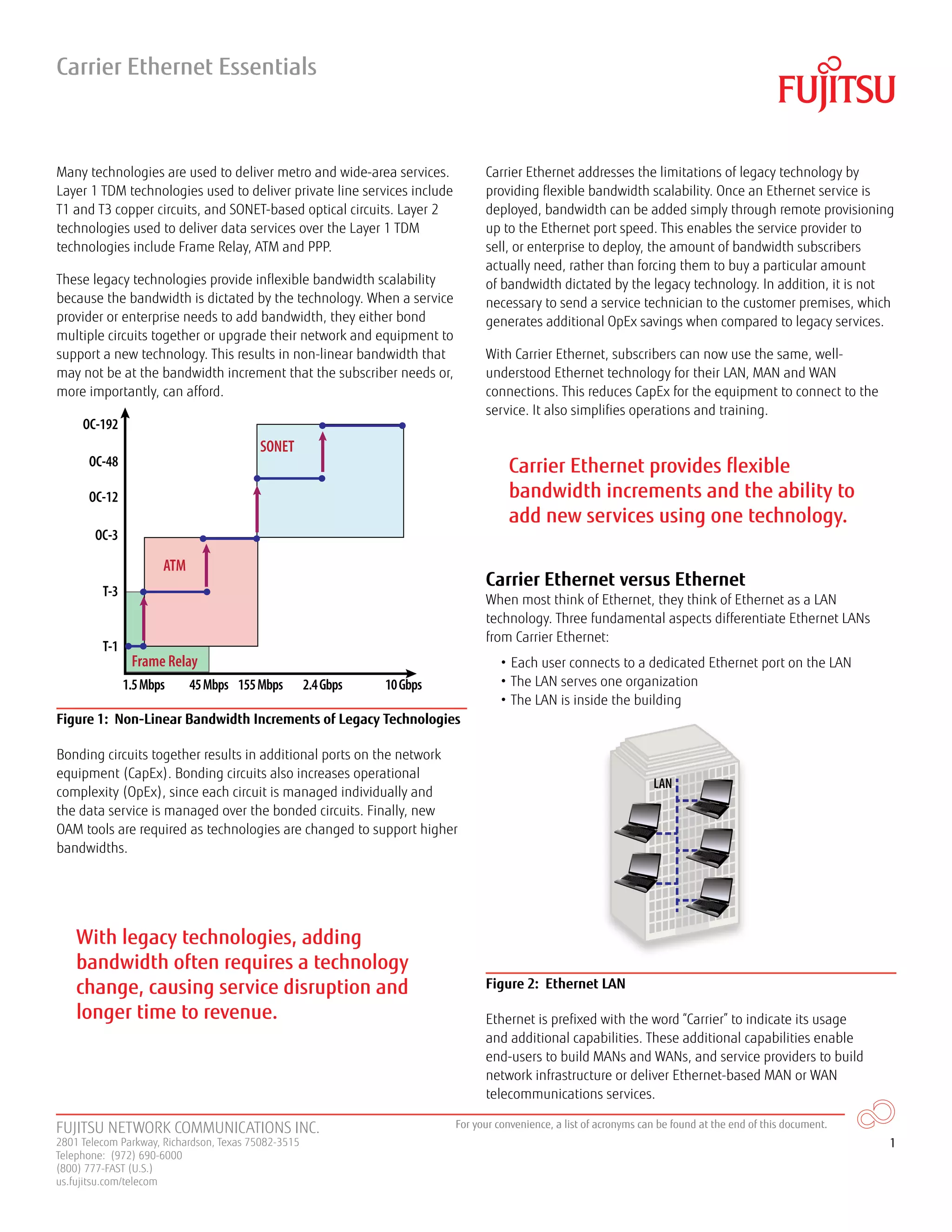
1) Carrier Ethernet provides more flexible bandwidth scalability compared to legacy technologies like T1, E3, SONET, and ATM. Bandwidth can be remotely provisioned up to the Ethernet port speed without needing new equipment or sending a technician.
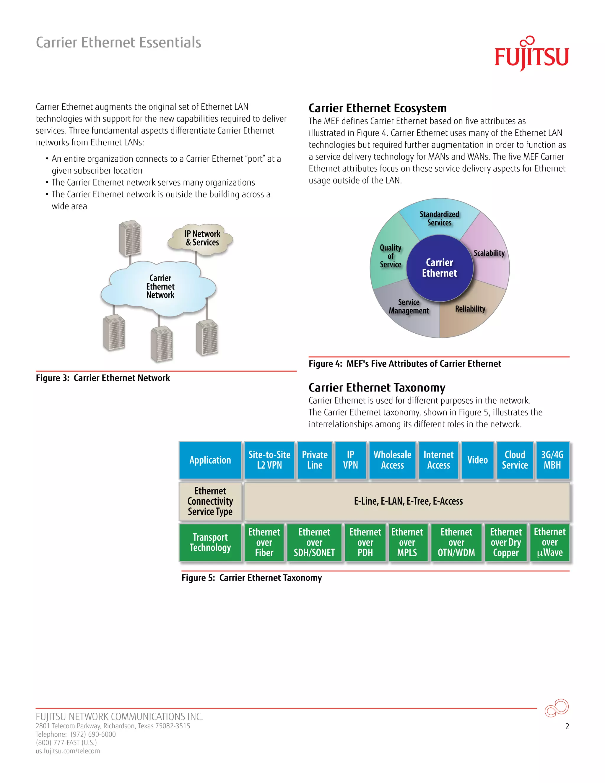
2) Carrier Ethernet differs from traditional Ethernet in that it connects entire organizations to an Ethernet port across wide areas between buildings rather than within a single building.
3) Carrier Ethernet can be implemented over various layer 1 transport technologies like fiber, SONET/SDH, MPLS, or microwave. It provides standardized Ethernet services like E-Line, E-LAN, and E-Tree.


![Uni fiee scm sesion 11 cdma [modo de compatibilidad]](https://cdn.slidesharecdn.com/ss_thumbnails/unifieescmsesion11cdmamododecompatibilidad-140824093227-phpapp02-thumbnail.jpg?width=640&height=640&fit=bounds)


