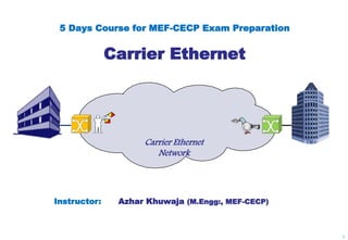
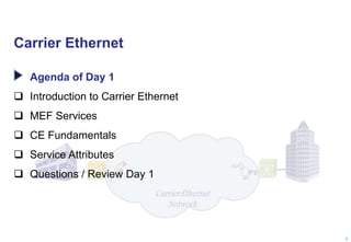
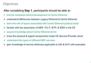
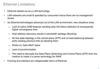
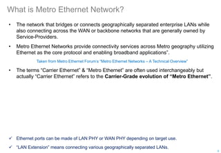
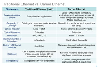
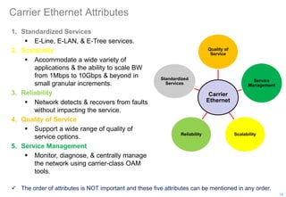
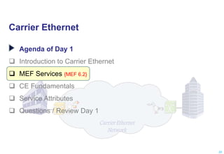
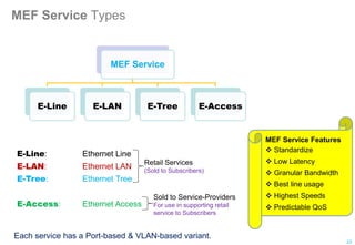
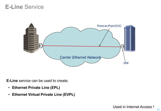
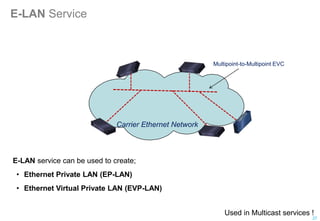
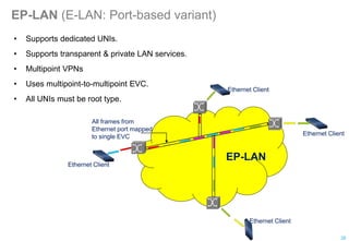
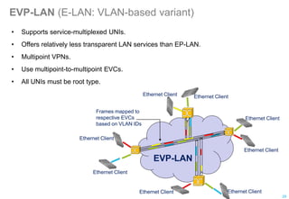
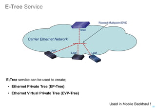
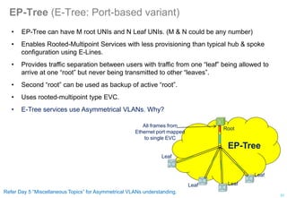
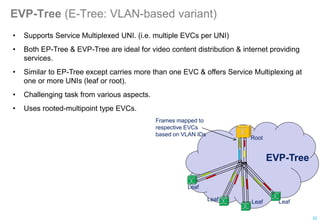
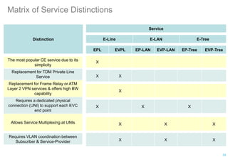
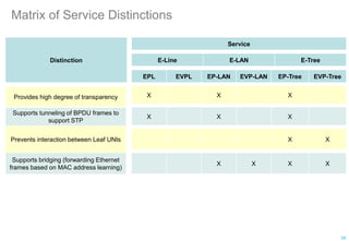
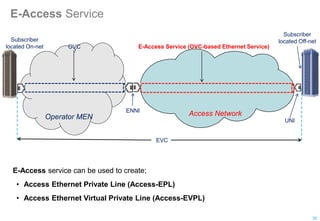
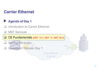
SlideShare a Scribd company logo
5 Days Course for MEF-CECP Exam Preparation
Carrier Ethernet
Carrier Ethernet
Network
Instructor: Azhar Khuwaja (M.Engg:, MEF-CECP)
1
Carrier Ethernet
Agenda of Day 1
 Introduction to Carrier Ethernet
 MEF Services
 CE Fundamentals
 Service Attributes
 Questions / Review Day 1
2
Objectives
After completing Day 1, participants should be able to:
 find the motivation behind development of Carrier Ethernet
 understand differences between Legacy Ethernet & Carrier Ethernet
 learn the role of layers associated with Carrier Ethernet protocol stack
 familiar with the association of MEF, ITU-T, IETF, & IEEE in the CE
 acquire knowledge about Carrier Ethernet terms
 know the physical & logical components inside CE Service-Provider cloud
 understand the types of different MEF services
 gain knowledge of service attributes applicable to UNI & EVC with examples
3
Carrier Ethernet
Agenda of Day 1
 Introduction to Carrier Ethernet {MEF 4}
 MEF Services
 CE Fundamentals
 Service Attributes
 Questions / Review Day 1
4
About MEF
• The Metro Ethernet Forum (MEF) is a global industry alliance comprising more than 220
organizations, including telecom Service-Providers, network equipment/software
manufacturers, semiconductor vendors, & testing organizations.
• MEF’s mission is to accelerate the worldwide adoption of Carrier-class Ethernet networks
& services.
• MEF develops Carrier Ethernet technical specifications & implementation agreements to
promote interoperability & deployment of Carrier Ethernet worldwide.
• MEF’s official website is great source of information: www.mef.net
• You can find technical specifications, reference presentations, white papers, &
certification program details on above website.
• MEF also maintains Carrier Ethernet Reference Wiki which is great source of
knowledge & information. It is available at:
https://wiki.mef.net/display/CESG/MEF+Reference+Wiki
5
Recall “Ethernet Frame”
Minimum Frame Size = 64 Bytes
Typical Frame Size = 1518 Bytes
6
Why we love Ethernet?
Ethernet is a successful technology for LANs due to;
• Ubiquitous
• Higher Speeds
• Plug & Play capability
• Simplicity
• Multi point connectivity
• Low cost (cheaper hardware and infrastructure)
• Full Duplex Interfaces
• Use of virtual LANs
• Enhancements in Control Plane (from STP to Rapid STP and Multiple STP)
• No media dependency (run over any media from copper to multi-mode fiber)
• Easy to manage and scale (in use of enterprise networks since decades)
• Layer 2 advantages i.e. Switching belongs to Data Plane (less software more hardware
unlike IP)
• No TTL limits
• Best in granularity compare to any technology on earth (Bandwidth on Demand)
• Easy to learn (saves training budget)
7
Ethernet Limitations
• Ethernet started out as a LAN technology
• LAN networks are small & operated by consumers hence there are no management
issues.
• As Ethernet technologies advances out of the LAN environment, new situations arise;
o Lack of native OAM features resulting slow link failure detection & consequently
higher convergence time
o Host address discovery results in bandwidth wastage (flooding)
o No link state topology in the control plane (STP) and no load balancing between
ports wasting precious links by blocking them
o Works on “best effort” basis
o Lack of synchronization
o The need to decouple the Data Plane (Switching) and Control Plane (STP) from the
medium to make it a carrier technology for WAN.
• Framing and interface are indispensable items of Ethernet.
8
What is Metro Ethernet Network?
• The network that bridges or connects geographically separated enterprise LANs while
also connecting across the WAN or backbone networks that are generally owned by
Service-Providers.
• Metro Ethernet Networks provide connectivity services across Metro geography utilizing
Ethernet as the core protocol and enabling broadband applications”.
Taken from Metro Ethernet Forum’s “Metro Ethernet Networks – A Technical Overview”
• The terms “Carrier Ethernet” & “Metro Ethernet” are often used interchangeably but
actually “Carrier Ethernet” refers to the Carrier-Grade evolution of “Metro Ethernet”.
 Ethernet ports can be made of LAN PHY or WAN PHY depending on target use.
 “LAN Extension” means connecting various geographically separated LANs.
9
What is Carrier Ethernet?
• According to MEF, Carrier Ethernet is;
For Subscriber;
Carrier Ethernet is a service defined by five attributes that distinguish it from
traditional Ethernet.
For Service-Provider, Carrier Ethernet is simultaneously a;
 Set of certified network elements that connect to one another in order to transport
the services offered to the customer
 Platform of value added services
 Standardized service for all users
Taken from Metro Ethernet Forum’s publications
• Carrier refers to Service-Provider.
• This Ethernet is meant to be for carriers to provide services across Metro, Access, or
even global level networks.
10
Carrier Ethernet benefits
• For Subscriber (Enterprise);
 A converged network for triple play (voice, data, video) services saving costs.
 Standardizing on Ethernet reduces complexity & benefits IT staff support & training
budgets.
 High-speed, low-latency service is easily upgraded by changing the service policy.
• For Service-Provider;
 Technology convergence provides CAPEX & OPEX reductions
 Access network technologies leverage Ethernet to provide backhaul and the ability
to move volumes of traffic from subscribers to broadband aggregation devices
adjacent to the core network.
 Flexible Layer 2 VPN services, including private line, virtual private line, or emulated
LAN offer new revenue streams.
 Provide dependable Ethernet business services
 Scalable services with higher bandwidths & low cost.
 Robust reliability & availability for business applications.
11
Traditional Ethernet vs. Carrier Ethernet
Dimensions Traditional Ethernet (LAN) Carrier Ethernet
Services Available
(scope)
Enterprise data applications
Voice/TDM and data connectivity
applications such as internet access, L2
VPNs, storage and backup, HD video,
Mobile Backhaul etc.
Geography /
Coverage
Buildings or campuses (under very few
kilometers)
No restriction (as far as service providers
can carry)
Service-Provider Local IT staff Carrier Ethernet Service-Providers
Typical Customer Enterprise Enterprise
Bandwidth 10M, 100M, 1G From 1M to 10G
Maximum number of
Subscribers
In hundreds Hundreds of thousands
Delivery of Ethernet
Services
Best Effort
Numerous transport technologies options
with associated SLAs
Resiliency
LAN is spread over physically smaller
indoor areas so failures can be
addresses relatively quickly
Excellent resiliency as failures cause
significant impact over revenues
Manageability Manageable with very simple tools
Complex management requires
sophisticated tools & capabilities
12
Ethernet Service Model (from Service-Provider perspective)
Focus layer of MEF
Basic Service-Provider Model for delivering Ethernet Services
Source: MEF
13
Connectivity Layer
Data
Plane
Control
Plane
Management
Plane
(L2 VPN, IP VPN, Mobile Backhaul, Internet Access,
Wholesale Access, PDH etc.)
Applications Services Layer
Ethernet Services Layer
(Ethernet Connectivity Service Type, PDU)
Transport Services Layer
(IEEE 802.1, SDH, PDH, MPLS, OTN etc)
Ethernet Service Model
• MEF has defined a 3 layer model (ESM) which include APP layer, Ethernet layer, & TRAN
layer.
 APP: Application layer supports end-user applications
 ETH: Ethernet layer provides Ethernet connectivity services (also known as
Connectivity Layer)
o Uses services from its Transport Layer(s)
o Provides services to its Application Layer(s)
 TRAN: Transport layer provides delivery via various transport/networking
technologies
• Each layer has 3 associated operational planes; Data, Control, & Management.
• MEF's focus is Ethernet layer because Carrier Ethernet mostly belongs to this layer.
• Transport is next important layer as some CE attributes are closely related with this layer.
• Transport layer is probably the only layer whose all operational planes (Data / Control /
Management) are fully defined by concerned standards bodies.
14
Associated Planes of Ethernet Service Model
Source: MEF 4
Data Plane: Also referred to as User /Transport /Forwarding Plane.
Provides the functional elements required to steer the subscriber
flow, and supports the transport of subscriber traffic units among
CEN NEs.
Control Plane: Provides the functional elements that support distributed flow
management functions among NEs participating in the CEN Data
Plane.
Control Plane also provides the signaling mechanisms necessary to
support distributed set up, supervision & connection release
operations, among other flow control functions.
Management Plane: Provides the functional elements that support Fault, Configuration
(including flow and/or connection configuration), Account,
Performance and Security (FCAPS) functions, as well as any related
Operations, Administration and Maintenance (OAM) tools.
15
Carrier Ethernet Attributes
Carrier
Ethernet
Quality of
Service
Service
Management
Scalability
Reliability
Standardized
Services
 The order of attributes is NOT important and these five attributes can be mentioned in any order.
1. Standardized Services
 E-Line, E-LAN, & E-Tree services.
2. Scalability
 Accommodate a wide variety of
applications & the ability to scale BW
from 1Mbps to 10Gbps & beyond in
small granular increments.
3. Reliability
 Network detects & recovers from faults
without impacting the service.
4. Quality of Service
 Support a wide range of quality of
service options.
5. Service Management
 Monitor, diagnose, & centrally manage
the network using carrier-class OAM
tools.
16
MEF’s classification of technical documents
Technical Specification
• Document detailing the agreed upon definitions, scope, methods & procedures for a
component of Carrier Ethernet.
• Example: MEF 6.2, MEF 10.3
Implementation Agreement
• A document describing an agreement as to how options in existing technical
specifications or other standards bodies work shall be implemented.
• Example: MEF 8, 22.2
Abstract Test Suite
• A document describing how attributes of Carrier Ethernet technical specifications will be
tested for compliance against those specifications.
• Also called as Test Specification.
• Consist of a series of tests to be used to measure conformance to certain MEF
specifications.
• Example: MEF 9, MEF 14
17
Technical Specifications/IA/ATS enabling Carrier Ethernet
Important: Educational purpose only. For detailed, accurate, & up-to-date information visit MEF website.
Source: www.mef.net
18
Abstract
Test Suites
Service
Definitions
Service
Attributes
Service
Architecture
Management
Service
Operations
9 6.2 10.3 2 7.2 50
14 8 10.3.1 3 31 52
18 22.2 10.3.2 4 31.0.1 53
19 33 23.2 11 36.1 54
21 43 26.2 12.2 38 55
24 47 41 13 39
25 51 45 20 40
27 29 42
34 32 44
37 46
continue to next page …………
Technical Specifications/IA/ATS enabling Carrier Ethernet
continue from previous page …………
Important: For detailed, accurate, & up-to-date information visit MEF website.
Source: www.mef.net 19
Abstract
Test Suites
Service
Definitions
Service
Attributes
Service
Architecture
Management
Service
Operations
48
49
17
30.1
30.1.1
35.1
15
16
Carrier Ethernet
Agenda of Day 1
 Introduction to Carrier Ethernet
 MEF Services {MEF 6.2}
 CE Fundamentals
 Service Attributes
 Questions / Review Day 1
20
MEF Services
• The MEF defines a framework for delivering Ethernet services over carrier-grade
networks. The business model for this framework involves two principle stakeholders:
1. Subscriber: The organization purchasing the Carrier Ethernet service
2. Service-Provider: The organization providing the Carrier Ethernet service
• The service itself is an Ethernet connection between two or more sites. The sites belong
to the subscriber. The network connecting the sites belongs to the Service-Provider.
• Two functional components:
1. MEN (or CEN): The Service-Provider network used to transport Carrier Ethernet
services.
2. CE (Customer Edge Equipment): The equipment at the subscriber site that
connects to the CEN. The CE can be a router or bridge/switch.
• MEF defines a Service-Frame as an “Ethernet frame transmitted across the UNI towards
the Service-Provider” or “an Ethernet frame transmitted across the UNI towards the
subscriber”.
21
MEF Services
• Carrier Ethernet services provisioned across MAN or WAN can be;
 Point-to-Point (includes E-Line & E-Access services)
 Rooted-Multipoint
 Multipoint-to-Multipoint
• The underlying infrastructure used for delivery of Ethernet services does NOT have to be
Ethernet. (Transport layer technology is independent of the service above)
• Referred to as MEF Services by the Metro Ethernet Forum (MEF).
 The terms “Carrier Ethernet Network” & “Metro Ethernet Network” are often used
interchangeably.
 “Carrier Ethernet” refers to the carrier-grade evolution of “Metro Ethernet”.
Carrier Ethernet
Network
22
Note: The term CEN is more appropriate than MEN.
MEF Service Types
Each service has a Port-based & VLAN-based variant.
MEF Service
E-Line E-LAN E-Tree E-Access
E-Line: Ethernet Line
E-LAN: Ethernet LAN
E-Tree: Ethernet Tree
E-Access: Ethernet Access
MEF Service Features
 Standardize
 Low Latency
 Granular Bandwidth
 Best line usage
 Highest Speeds
 Predictable QoS
23
Retail Services
(Sold to Subscribers)
Sold to Service-Providers
For use in supporting retail
service to Subscribers
E-Line Service
Point-to-Point EVC
E-Line service can be used to create;
• Ethernet Private Line (EPL)
• Ethernet Virtual Private Line (EVPL)
Carrier Ethernet Network
UNI
24
Used in Internet Access !
EPL (E-Line: Port-based variant)
• Ethernet Private Line (EPL) is defined by MEF 6.2, MEF 10.3, & ITU-T G.8011.1
• MEF 6.2 says "An EPL service uses a Point-to-Point EVC between two UNIs & provides a
high degree of transparency for Service Frames between the UNIs it interconnects."
• A whole Ethernet port is switched across a Service-Provider network.
• Replaces a TDM private line.
• Dedicated UNIs for Point-to-Point connections.
• Single Ethernet Virtual Connection (EVC) per UNI.
• Uses point-to-point EVC.
• All UNIs must be root type.
• No VLAN coordination required between subscriber & Service-Provider.
Ethernet Client
All frames from
Ethernet port mapped
to single EVC
Ethernet Client
25
EVPL (E-Line: VLAN-based variant)
• Ethernet Virtual Private Line (EVPL) is defined by MEF 6.2 & ITU-T G.8011.2.
• VLAN sets can be switched to multiple destinations.
• Replaces Frame Relay & ATM services.
• Supports Service Multiplexed UNI. (i.e. multiple EVCs per UNI)
• Allows single physical connection (UNI) to customer premise equipment for multiple
virtual connections.
• Its UNI must be configurable to support multiple EVCs.
• Provides relatively lower transparent transmission than EPL.
• Uses point-to-point EVCs with all root UNIs.
Frames mapped to
respective EVCs
based on VLAN IDs
Ethernet Client
Ethernet Client
EVPL
Ethernet Client
Ethernet Client
EVC1
EVC2
26
E-LAN Service
E-LAN service can be used to create;
• Ethernet Private LAN (EP-LAN)
• Ethernet Virtual Private LAN (EVP-LAN)
Multipoint-to-Multipoint EVC
Carrier Ethernet Network
27
Used in Multicast services !
EP-LAN (E-LAN: Port-based variant)
Ethernet Client
All frames from
Ethernet port mapped
to single EVC Ethernet Client
EP-LAN
Ethernet Client
Ethernet Client
• Supports dedicated UNIs.
• Supports transparent & private LAN services.
• Multipoint VPNs
• Uses multipoint-to-multipoint EVC.
• All UNIs must be root type.
28
EVP-LAN (E-LAN: VLAN-based variant)
Ethernet Client
Ethernet Client
EVP-LAN
Ethernet Client
Ethernet Client
Ethernet Client
Ethernet Client
Ethernet Client
Ethernet Client
Frames mapped to
respective EVCs
based on VLAN IDs
• Supports service-multiplexed UNIs.
• Offers relatively less transparent LAN services than EP-LAN.
• Multipoint VPNs.
• Use multipoint-to-multipoint EVCs.
• All UNIs must be root type.
29
E-Tree Service
E-Tree service can be used to create;
• Ethernet Private Tree (EP-Tree)
• Ethernet Virtual Private Tree (EVP-Tree)
Rooted-Multipoint EVC
Carrier Ethernet Network
Root
Leaf
Leaf Leaf
30
Used in Mobile Backhaul !
EP-Tree (E-Tree: Port-based variant)
• EP-Tree can have M root UNIs and N Leaf UNIs. (M & N could be any number)
• Enables Rooted-Multipoint Services with less provisioning than typical hub & spoke
configuration using E-Lines.
• Provides traffic separation between users with traffic from one “leaf” being allowed to
arrive at one “root” but never being transmitted to other “leaves”.
• Second “root” can be used as backup of active “root”.
• Uses rooted-multipoint type EVC.
• E-Tree services use Asymmetrical VLANs. Why?
EP-Tree
Root
Leaf
Leaf
Leaf
Leaf
All frames from
Ethernet port mapped
to single EVC
31
Refer Day 5 “Miscellaneous Topics” for Asymmetrical VLANs understanding.
EVP-Tree (E-Tree: VLAN-based variant)
• Supports Service Multiplexed UNI. (i.e. multiple EVCs per UNI)
• Both EP-Tree & EVP-Tree are ideal for video content distribution & internet providing
services.
• Similar to EP-Tree except carries more than one EVC & offers Service Multiplexing at
one or more UNIs (leaf or root).
• Challenging task from various aspects.
• Uses rooted-multipoint type EVCs.
EVP-Tree
Root
Leaf
Leaf
Leaf
Leaf
Frames mapped to
respective EVCs
based on VLAN IDs
32
Matrix of Service Distinctions
33
Distinction
Service
E-Line E-LAN E-Tree
EPL EVPL EP-LAN EVP-LAN EP-Tree EVP-Tree
The most popular CE service due to its
simplicity
Replacement for TDM Private Line
Service
Replacement for Frame Relay or ATM
Layer 2 VPN services & offers high BW
capability
Requires a dedicated physical
connection (UNI) to support each EVC
end point
Allows Service Multiplexing at UNIs
X
X X
X
X X X
X X X
Requires VLAN coordination between
Subscriber & Service-Provider X X X
Matrix of Service Distinctions
34
Distinction
Service
E-Line E-LAN E-Tree
EPL EVPL EP-LAN EVP-LAN EP-Tree EVP-Tree
Provides high degree of transparency
Supports tunneling of BPDU frames to
support STP
Prevents interaction between Leaf UNIs
Supports bridging (forwarding Ethernet
frames based on MAC address learning)
X X X
X X X
X X
X X X X
E-Access Service
E-Access service can be used to create;
• Access Ethernet Private Line (Access-EPL)
• Access Ethernet Virtual Private Line (Access-EVPL)
UNI
ENNI
Access Network
Operator MEN
E-Access Service (OVC-based Ethernet Service)
Subscriber
located Off-net
EVC
Subscriber
located On-net
35
OVC
Access-EPL (E-Access: Port-based variant)
• Provides EPL type service (Access-EPL) for subscribers located off-net.
• Uses Point-to-Point OVC over Access-Provider network.
• Defined by MEF 33.
• All-to-One Bundling is always YES.
• All frames at UNI are mapped to the service.
• All service frames at ENNI are identified by S-Tag.
Access-EPL
All frames from
Ethernet port mapped
to service.
UNI
ENNI Access Network
Operator MEN
OVC
Subscriber
located
Off-net
EVC
Subscriber
located On-net
36
Access-EVPL (E-Access: VLAN-based variant)
• Provides EVPL type service (Access-EVPL) for subscribers located off-net.
• Uses Point-to-Point OVC over Access-Provider network. (see MEF 33)
• Bundling & Service Multiplexing are always YES.
• Frames are mapped to the OVC at UNI based on CE-VLAN IDs.
• CE-VLAN ID translation is not supported.
• At ENNI, service frame identification is carried via S-Tag.
UNI
ENNI Access Network
Operator CEN
OVC
EVC
Access-EVPL
Subscriber
located Off-
net
Subscriber
located On-net
37
Frames mapped to
respective OVCs
based on CE-VLAN
IDs
Recognize Service(s)?
Root
Leaf
Leaf
Leaf
Leaf
Root
Service Multiplexing
How many EVC(s)?
How many Service(s)?
What kind of MEF Service(s)?
How many EVC(s)?
How many Service(s)?
What kind of MEF Service(s)?
Root
Leaf
Leaf
Leaf
Leaf
Root
Case 1 Case 2
38
Carrier Ethernet
Agenda of Day 1
 Introduction to Carrier Ethernet
 MEF Services
 CE Fundamentals {MEF 10.3, MEF 13, MEF 26.2}
 Service Attributes
 Questions / Review Day 1
39
UNI (User Network Interface)
• UNI is the physical interface or port that is demarcation between the Customer &
Service Provider.
• UNI at customer side is UNI-C & network side is UNI-N (UNI = UNI-C + UNI-N)
• UNI-N is generally referred as UNI (though technically incorrect)
• UNI-N is always provided by Service Provider. (UNI-C belong to customer port)
• UNI in a Carrier Ethernet Network is a physical Ethernet interface at operating speeds of
10Mbps, 100Mbps, 1Gbps, or 10Gbps.
• Each UNI-N is assigned alphanumeric string which identify it within CE Service
Provider’s network. (Example: KRPOP1-Node2-Slot2-Port4)
• Known as “External Interface” like ENNI.
• A UNI must be dedicated to a single subscriber.
• UNI is further classified into Type 1 and Type 2 by MEF.
• UNI type 2 & above support Port Failure Protection via L2CP.
• UNI-N provides security by allowing Security Filters (ACL type commands) to filter out
all un-recognized MAC addresses.
40
Subscriber
LAN
UNI Classification
• UNI type 1 is manually configurable (MEF 13)
• UNI type 2 is automatically configurable via E-LMI & manageable via OAM (MEF 20)
CEN
Subscriber
LAN
UNI-C UNI-N
UNI
UNI-N UNI-C
UNI
UNI
UNI type 2
UNI type 2.1 UNI type 2.2
UNI type 1
41
UNI Frame Forwarding
• Both UNI-C & UNI-N have three planes which are Management, Control, & Data.
• Customer to Customer Service Frames including Customer’s data, control &
management frames are handled by UNI-C & UNI-N Data Planes.
• Control frames between Customer & Service-Provider are handled by UNI-C & UNI-N
Control Planes.
• Management frames between Customer & Service-Provider are handled by UNI-C &
UNI-N Management Planes.
• Are there any Data frames between Customer & Service-Provider to handle?
Data
Plane
Access Link
Management Plane
UNI-N
UNI-C Trunk Link
(Network Side)
Service Frame Flow
EMS Interface
Management Plane
Control
Plane
Control
Plane Data
Plane
42
Source: MEF
EVC (Ethernet Virtual Connection)
Ethernet Virtual Connection
Carrier Ethernet Network
• EVC is a Service Container or transport connection.
• EVC is a construct that performs two functions;
1. It indicates an association of two or more UNIs for the purpose of delivering an
Ethernet flow between subscriber sites across the Carrier Ethernet network. These
UNIs are said to be “in the EVC”. Source: MEF
2. It prevents data transfer between subscriber sites that are not part of the same
EVC.
43
EVC
• EVCs can be bundled or multiplexed on the same UNI.
• EVC connects two or more subscriber sites (UNI’s).
• There may be more than one subscriber flows mapped to a particular EVC, therefore,
EVC has ability to deal with data privacy & security concerns.
• Like UNIs, all EVCs are assigned alphanumeric strings which identify them within CE
Service Provider’s network.
• EVC ID is an arbitrary string administered by the Service-Provider that is used to identify
an EVC within the MEN.
• The EVC ID must be unique across all EVCs in the MEN & it is intended for
management & control purposes.
• The EVC ID is not carried in any field in the Service Frame.
• EVC ID example: ABC Service-Provider uses “EVC-00018-ABC-XYZ” to represent the
18th EVC in the MEN which belong to the customer XYZ.
44
Remember “Bridge Domain” ?
EVC
EVC types
Point-to-Point Multipoint-to-Multipoint Rooted-Multipoint
• Two conditions that govern the delivery of Ethernet frames over an EVC.
1. A service frame must never be delivered back to the UNI where it originated.
2. The Ethernet frame contents (including MAC addresses) must remain unchanged.
(FCS may be an exception)
• Loopback frames are exception which can be delivered back to the originated UNI.
• EVC attributes are Bandwidth Profile, Performance, CE-VLAN Class of Service
Preservation, Service Frame Delivery etc. (details are discussed later)
• Three types of EVCs:
45
EVC Types
• In Point-to-Point EVC, exactly two UNIs must be associated with one another.
• In Multipoint-to-Multipoint EVC, two or more UNIs must be associated with one another.
• Point-to-Point EVCs are the basis of E-Line service which include EPL & EVPL.
• Multipoint-to-Multipoint EVCs are basis of E-LAN service including EP-LAN & EVP-LAN
• Rooted-Multipoint EVC is used for E-Tree services which includes EP-Tree and EVP-
Tree.
Point-to-Point Multipoint-to-Multipoint Rooted-Multipoint
46
ENNI (External Network to Network Interface)
• ENNI is defined as a reference point representing the boundary between two Operator
MENs (or Operator CENs) that are operated as separate administrative domains.
• ENNI provides interconnection point (or link) between two Operator MENs (or Operator
CENs) when more than one Operator is involved in delivering MEF service(s).
Operator 4
CEN
Operator 1
CEN
Operator 2
CEN
Operator 3
CEN
UNI
ENNI
47
Operator y CEN
Operator x CEN
ENNI
• ENNI is simply the point where Service-Provider & the Wholesale Operator (Out-of-
Franchise) hand off the service(s) to each other.
• ENNI = ENNI-Nx + ENNI-Ny (where x & y are different operator ports linking each other)
• Not required if EVC is spread across single CEN only.
• Known as “External Interface” like UNI.
• When an EVC associates UNIs which are located at different Operator MENs, the EVC is
realized by concatenating OVCs.
• Ethernet-Access services always require ENNI.
• Frames are exchanged between ENNI-Nx & ENNI-Ny. Both belong to different operators.
• Link between ENNI-Nx & ENNI-Ny can be protected by applying redundancy (e.g. LAG).
• ENNI is always in Color Aware mode if BW Profile is implemented.
ENNI-Nx
ENNI
48
ENNI-Ny
OVC (Operator Virtual Connection)
• An OVC is the building block for constructing an EVC spanning multiple Operator CENs.
• Not required if EVC is spread across single CEN only.
• An OVC can informally be thought of as an association of “External Interfaces” within the
same Operator CEN. (except UNI to UNI)
• An OVC is the association of two or more external interfaces (UNI or ENNI) within an
Operator MEN, where at-least one of the external interfaces is an ENNI.
• An OVC must include at-least one ENNI because otherwise it would be an EVC.
• An OVC is always required for E-Access services for connectivity with CEN.
UNI
ENNI
Operator CEN
Operator CEN
OVC Subscriber
EVC
Subscriber
49
INNI (Internal Network to Network Interface)
• As the name says, it is an Internal Interface (unlike UNI & ENNI).
• One common location of INNI is between two different transport technologies within
single CEN.
• The network side port of NID can be called as INNI.
• INNI is an open interface between two network elements within the same CEN.
• Not much discussed in MEF publications due to internal nature of interface.
UNI-N
Operator x (Service-
Provider) MEN
Subscriber Site
I-NNI
Operator y
MEN
I-NNI
Subscriber Site
UNI-C
ENNI
UNI-C
UNI-N
ENNI-Nx ENNI-Ny
Provider Edge
Switch
50
Distinguish between Service-Provider & Operator
• It is not necessary that a subscriber’s required service start & end within the coverage
area of a particular Service-Provider & its operated network.
• The MEF Service may have to spread across various Operator MENs.
• Service-Provider may or may not be an Operator.
• In our figure, Service-Provider is also Operator of MEN A.
Operator A (Service-Provider)
MEN Operator C
MEN
Operator B
MEN
ENNI ENNI UNI
UNI
Subscriber Site Subscriber Site
51
Distinguish between Service-Provider & Operator
• Delivering end-to-end service across multiple Operator networks is the Service-
Provider’s responsibility.
• A subscriber only deals with Service-Provider & may not be aware of the several
Operators involvement for its service.
• Service-Provider deals with Operator(s) involved & make agreements with them.
• Wholesale Operators (which facilitate Service-Providers to spread service across their
administrative area) are also known as Out-of-Franchise Operators.
• Out-of-Franchise may be called Off-net. (Off-net generally used for E-Access
subscribers located out-of-way).
52
Service Level Agreement (SLA)
• SLA represents a contract which defines a variety of network parameters between the;
 Service-Provider & the Subscriber
 Service-Provider & Operator(s) ……may not be required as it depends on
Operator’s involvement for service coverage
• SLA sets up series of parameters & values the Service-Provider (or Operator) will meet
or be penalized if it fails to meet the terms of agreement.
• SLA is on End-to-End basis.
• SLA has legal & business significance.
53
Service Level Specification (SLS)
• SLS is the concrete part of the SLA.
• SLS is the technical parameters describing service quality including;
 Bandwidth
 Delay
 Jitter (IFDV)
 Availability
 Resiliency
• SLS also deals with non-technical parameters
 Service availability time (in the ratio of complete billing time)
 Time constraints of solving service issues
• MEF 6.2 & MEF 10.3 define the terms, tools, & the way to measure ingredients of SLS.
54
Carrier Ethernet
Agenda of Day 1
 Introduction to Carrier Ethernet
 MEF Services
 CE Fundamentals
 Service Attributes {MEF 6.2, MEF 10.3, MEF 13, MEF 20, MEF 26.2}
 Questions / Review Day 1
55
Defining MEF Services
MEF Services
MEF Service Type
UNI, EVC, & UNI/EVC
attributes associated with
MEF Service Type
Values for each of the UNI/EVC
attributes associated with MEF
Service Type
MEF
Standardized:
Ethernet
Services
Definition
Framework
E-Line / E-LAN / E-Tree
Defined by
Defined by
Defined by
Traffic Parameters(BW Profile)
Ethernet Physical Interface
Service Frame Delivery
VLAN Tag Support
Service Multiplexing
Bundling
EVC Performance
Etc. ….
Actual values of above
parameters to ultimately define
MEF Services.
NOTE: Some of these
attributes are applicable to
UNI, others to EVCs, & still
others to both UNI & EVCs.
56
Note: E-Access service is not shown here due to OVC-based service nature.
Service Attributes
Three categories of service attributes are associated with a particular MEF service.
 service attributes applicable to particular UNI only.
 service attributes applicable to EVC as a whole.
 service attributes applicable to particular EVC at a particular UNI.
Service Attributes
UNI
Service Attributes
EVC
Service Attributes
EVC per UNI
Service Attributes
 Next slide displays comprehensive list of service attributes belonging to each category.
 Assuming there is only one MEN involved which is operated by Service-Provider.
57
List of Service Attributes
UNI Service Attributes EVC per UNI Service Attributes EVC Service Attributes
UNI Identifier UNI EVC ID EVC Type
Physical Medium CE-VLAN ID / EVC Map EVC ID
Speed Ingress Bandwidth Profile Per EVC UNI List
Mode Ingress Bandwidth Profile Per CoS Identifier Maximum Number of UNIs
MAC Layer Egress Bandwidth Profile Per EVC EVC MTU size
UNI MTU Size Egress Bandwidth Profile Per CoS Identifier CE-VLAN ID Preservation
Service Multiplexing CE-VLAN CoS Preservation
Bundling Unicast Service Frame Delivery
All to One Bundling Multicast Service Frame Delivery
CE-VLAN ID for untagged and priority
tagged Service Frames
Broadcast Service Frame Delivery
Maximum number of EVCs
Layer 2 Control Protocol Processing (only
applies for L2CPs passed to the EVC)
Layer 2 Control Protocols Processing EVC Performance
Ingress Bandwidth Profile Per UNI
Egress Bandwidth Profile Per UNI
58
UNI Service Attributes
Here is the list of UNI Service Attributes.
 UNI Identifier
 Physical Medium
 Speed
 Mode
 MAC Layer
 UNI MTU Size
 Service Multiplexing
 Bundling
 All to One Bundling
 CE-VLAN ID for untagged & priority-tagged Service Frames
 Maximum Number of EVCs
 Layer 2 Control Protocols Processing
 Ingress Bandwidth Profile per UNI
 Egress Bandwidth Profile per UNI
Service
Attributes
UNI Service
Attributes
EVC Service
Attributes
EVC per UNI
Service Attributes
Ethernet Physical
Interface
 The listed items may vary depending on service type in question ! 59
UNI Service Attributes: Ethernet Physical Interface
Physical Medium:
• Any one of the following IEEE 802.3 Ethernet PHYs can be used:
 10BASE-T
 100BASE-T including 100BASE-TX & 100BASE-FX
 1000BASE-X including 1000BASE-SX, 1000BASE-LX, & 1000BASE-T
 10GBASE-SR, 10GBASE-LX4, 10GBASE-LR, 10GBASE-ER, 10GBASE-SW,
10GBASE-LW, & 10GBASE-EW
Speed:
• 10 Mbps, 100 Mbps, 10/100 Mbps Auto-Negotiation, 10/100/1000 Mbps Auto-
Negotiation, 1 Gbps, or 10 Gbps.
Mode:
• Full Duplex (FDX)
MAC Layer:
• IEEE 802.3 - 2005
60
UNI Service Attributes
UNI Identifier:
• Arbitrary text string to identify the UNI.
• Examples: U1, U50 etc.
• More practical example is like; “KRPOP1-Node2-Slot2-Port4" which signify Port 4 in
Slot 2 of Node 2 in Karachi POP1.
UNI MTU Size:
• The maximum sized Service Frame allowed at the UNI.
• Must be ≥ 1522 bytes (1518 + 4)
• A similar attribute “EVC MTU Size” belongs to EVC Service Attributes.
61
What is Jumbo Frame?
UNI Service Attributes: Service Multiplexing, Bundling, All-
to-One Bundling
Service Multiplexing:
• Ability of UNI (a physical interface) to support multiple EVCs and precludes the need
for a separate UNI to support each EVC.
Bundling:
• Allows two or more CE-VLAN IDs to be mapped to a single EVC at a UNI. (Multiple
CE-VLAN IDs per EVC but multiple EVCs per UNI)
All-to-One Bundling:
• An UNI attribute in which all CE-VLAN IDs are associated with a single EVC. (Only
ONE EVC per UNI)
• All-to-One bundling is required in order to support private services (EPL, EP-LAN, or
EP-Tree). In such a setting, there is a single EVC at the UNI and all service frames
are mapped to this EVC.
 What if I have only ONE CE-VLAN ID mapped to an EVC of an EPL, can I say “All-to-One-
Bundling” = Yes?
62
UNI Service Attributes: Service Multiplexing, Bundling, All-
to-One Bundling
• All-to-One-Bundling and Bundling can never be YES at the same time (Mutually
Exclusive).
• All-to-One-Bundling is a sub set of Bundling (special case).
• CE-VLAN ID Preservation should always be set to YES when either Bundling or All-to-
One-Bundling is YES.
• If Bundling or All-to-One-Bundling is YES, CE-VLAN ID Preservation must be YES.
NOTE:
All-to-One Bundling is applicable ONLY to port-based MEF services. (EPL, EP-LAN, EP-
Tree)
Bundling may exist in VLAN-based MEF services. (EVPL, EVP-LAN, EVP-Tree)
Service Multiplexing NOT possible in port-based MEF services. (EPL, EP-LAN, EP-Tree)
Service Multiplexing may exist in VLAN-based MEF services. (EVPL, EVP-LAN, EVP-
Tree) {should exists in most cases}
63
Question: All-to-One Bundling
All-to-One Bundling is NOT applicable to which of the following MEF service.
(select one)
a) EPL
b) EVPL
c) EP-LAN
d) EP-Tree
e) None of Above
64
Answer
b) EVPL
Five valid combinations of Service Multiplexing, Bundling,
& All-to-One Bundling
Valid Combination 1:
Service Multiplexing = No
Bundling = No
All-to-One Bundling = No
Example: EVPL having ONE EVC with ONE CE-VLAN ID mapped to the EVC.
Valid Combination 2:
Service Multiplexing = Yes
Bundling = No
All-to-One Bundling = No
Example: EVPL having multiple VLAN-based EVCs with only ONE CE-VLAN ID
mapped to each EVC.
Valid Combination 3:
Service Multiplexing = Yes
Bundling = Yes
All-to-One Bundling = No
Example: EVPL having multiple VLAN-based EVCs with two or more CE-VLAN IDs
mapped to each EVC.
65
Five valid combinations of Service Multiplexing, Bundling,
& All-to-One Bundling
Valid Combination 4:
Service Multiplexing = No
Bundling = Yes
All-to-One Bundling = No
Example: EVPL having ONE VLAN-based EVC with two or more CE-VLAN IDs
mapped to it.
Valid Combination 5:
Service Multiplexing = No
Bundling = No
All-to-One Bundling = Yes
Example: EPL having one port-based EVC with all service frames mapped to the EVC.
66
UNI Service Attributes
CE-VLAN ID for Untagged & Priority-tagged Service Frames:
• A Service Frame consists of the first bit of the Destination MAC Address through the
last bit of the Frame Check Sequence.
• Priority-Tagged service frames are those whose VLAN ID is “0”.
• Untagged service frames are L2CP frames except some L2CPs like STP/ PVSTP etc.
• CE-VLAN ID for untagged & priority tagged Service Frames must be in the range of 1-
4094.
• This attribute is not required for port-based services. (when “All-to-One Bundling=Yes”)
• Since the UNI is dedicated to a single Subscriber, only one Subscriber can access the
EVCs at the UNI.
MEN / CEN
Stacking
Tagging
tag w/o tag
w tag w/o tag
double tag
w tag
tagged
tagged
double tag
w tag
tagged
tagged
tag
w tag
w/o tag
w/o tag
LAN
LAN
67
NID NID
Traffic Direction
UNI Service Attributes
Maximum number of EVCs:
• This attribute defines the maximum number of EVCs that the UNI can support.
• It must have a value of at least one (like in case of Port-based services).
• Chart below shows the difference among Tagging, Stacking, & Stripping.
• Stripping is exact opposite of Stacking.
Ingress Egress
Tagging
ETH Frame ETH Frame + VLAN TAG
ETH Frame + VLAN TAG ETH Frame + VLAN TAG
Stacking
ETH Frame ETH Frame + VLAN TAG
ETH Frame + VLAN TAG ETH Frame + VLAN TAG + VLAN TAG
Stripping
ETH Frame + VLAN TAG + VLAN TAG ETH Frame + VLAN TAG
ETH Frame + VLAN TAG ETH Frame
68
UNI Service Attributes: Layer 2 Control Protocol Processing
• L2CP frames are recognized on the basis of their destination MAC Addresses.
 01-80-C2-00-00-00 through 01-80-C2-00-00-0F (Bridge Block of Protocols)
 01-80-C2-00-00-20 through 01-80-C2-00-00-2F (GARP Block of Protocols)
• Examples of L2CPs are STP, PAUSE (used for flow control 802.3x), LACP / LAMP, Link
OAM, Port Authentication (802.1x), E-LMI, LLDP, GARP / MRP.
• Refer MEF 6.2 / MEF 10.3 for detailed information on handling L2CPs. (along with
complete L2CP list)
• In case of identical MAC Address of L2CPs, another field “Ether Type” help in recognizing
frame type.
• For “UNI service attribute of L2CP Processing”, one of the following options should be
specified:
 Peer (CEN will participate in the protocol)
 Discard (CEN will ignore the L2CP frame which means
that it will neither participate in the protocol nor it will forward the frame)
 Pass to EVC
 Peer & Pass to EVC 69
Refer EVC Service Attribute “L2CP Processing” for further outcome.
Don’t bother looking at EVC
Service Attribute “L2CP
Processing”.
UNI Service Attributes: Layer 2 Control Protocol Processing
• This attribute (L2CP Processing) allow L2CP Processing to be independently configured
for each protocol & for each service.
• If UNI Service Attribute “L2CP Processing = Peer (or Discard)” then you don’t have to
worry about EVC Service Attribute “L2CP Processing”. It will Peer (or Discard) no matter
what options you selected in EVC Service Attribute “L2CP Processing”.
• If UNI Service Attribute “L2CP Processing = Pass to EVC (or Peer & Pass to EVC)” then
you also need to refer EVC Service Attribute “L2CP Processing” for further outcome.
70
Above table shows outcome when UNI Service Attribute “L2CP Processing” & EVC Service Attribute
“L2CP Processing” are both considered in combination.
BW Profile (Traffic Parameters CIR, CBS, EIR, EBS)
• Bandwidth Profile is one of the “UNI” or “EVC per UNI” attributes defined during
provisioning of MEF service.
• Bandwidth Profile is a characterization of Ethernet frames (e.g. frames from a customer
into a UNI)
• Bandwidth Profile consists of 4 traffic parameters;
1. Committed Information Rate (CIR) – SLA based
2. Committed Burst Size (CBS) – SLA based
3. Excess Information Rate (EIR) – not subject to SLA & optional
4. Excess Burst Size (EBS) – not subject to SLA & optional
• BW Profile should be applied at Ingress node (applying at Egress node is optional);
 Ingress Bandwidth Profile per UNI (part of UNI service attributes)
 Ingress Bandwidth Profile per EVC (part of EVC per UNI service attributes)
 Ingress Bandwidth Profile per CoS Identifier (part of EVC per UNI service attributes)
• Multiple services can be offered over a subscriber UNI & each of these services can
have its own Bandwidth Profile. 71
Bandwidth Profile Visualization
 SLAs are based on CIR/CBS (Green Service Frames only) 72
Traffic Stream
Tokens flow into
the bucket at a
constant rate
The size of the
token bucket
reflects the
maximum burst
size Each Service Frame needs one token per byte
If token bucket fills, excess tokens are discarded.
Constant Rate
Burst Size
Single Rate Scenario
Two Rate Scenario
Traffic Stream
CIR/8
CBS
EIR/8
EBS
UNI Service Attributes: Ingress / Egress BW Profile per UNI
UNI-N
EVC 1
Ingress BW Profile
per UNI
• Can not be used for port based MEF services since “Ingress BW Profile per UNI” would
be same as “Ingress BW Profile per EVC”.
• Port based services (e.g. EPL) would always use “Ingress BW Profile per EVC” to
avoid duplication. (“Ingress BW Profile per CoS ID” can be used though)
• For all BW Profile types, EIR & EBS are based on available BW (non SLA).
• Should the value of CIR be kept same on both ingress UNIs of an EPL service? How
about Asymmetric bandwidth in uplink and downlink directions?
UNI-N
EVC 2
Egress BW Profile
per UNI
EVC 1
EVC 2
73
Bandwidth Profile Facts
• At Egress, Bandwidth Profile is optional but un-necessary in case of EPL & EVPL.
• CBS & EBS should have higher values at Egress than Ingress in case of E-LAN
services. Higher EBS and CBS can bear burstiness caused within MEN (or CEN).
• “Ingress BW Profile per UNI” & “Ingress BW Profile per EVC” are same in case of port
based services like EPL, EP-LAN, EP-Tree. Therefore in order to avoid duplication,
“Ingress BW Profile per UNI” is not used & only “Ingress BW Profile per EVC” is used.
(MEF 6.2, Table 10)
• Sum of all CIRs associated with EVCs should be less than UNI speed (Layer 1 bytes).
• If CIR=0 and EIR=“some value” then it means only “best effort” traffic is allowed.
• It is prohibited to implement more than one BW Profile types which may overlap each
other’s services.
• BW Profile helps eliminate burstiness of customer traffic from spreading into Service
Provider network.
• It allocates desirable green and/or yellow traffic speed(s) for customers as per SLA.
• Peak Information Rate = EIR + CIR
• Any advantage of applying CIR / EIR at Egress?
74
Color Marking (Rate Enforcement)
• Rate enforcement applied via two-rate (double stage consists of Committed & Excess)
states.
• Three Color Marker (TCM) algorithm (Green, Yellow, Red) implemented as Token
Bucket.
• GREEN Traffic:
 Everything below CIR. All performance metrics guaranteed by SLA.
 A Green Frame can not be converted to Yellow inside MEN under any
circumstances.
• YELLOW Traffic:
 Everything between CIR and EIR (above CIR & below EIR)
 Yellow traffic accepted only if network capacity permits (without any performance
guarantee)
 Drop Eligible traffic (Best Effort)
 A Yellow Frame may be converted to Green inside MEN if resources permit (rarely)
• RED Traffic:
 Everything exceeding EIR, traffic discarded.
75
Color Mode
• Color Mode parameter specifies whether the UNI is operating in a color-aware or color-
blind mode.
• When in a color-aware mode, the prior color associated with an incoming service frame
is employed.
• In the color-blind mode, the prior color indication is ignored.
Ingress
UNI-N
Egress
UNI-N
Color Blind Mode
Color Aware Mode
76
UNI-C
Ingress
UNI-N
Egress
UNI-N
UNI-C
Customer’s Uncolored
Frames
Customer’s Colored
Frames
Coupling Flag
• CF is a Bandwidth Profile parameter.
• It allows the choice between two modes of operation (value of 0 or 1)
• It likely increases the number of Yellow frames (if CF=1)
• Not useful in “Color Blind” mode.
• Implementation operates on whole frames basis.
• If Yellow token bucket fills, excess tokens are discarded.
77
CBS EBS
CIR / 8 EIR / 8
CF = 1
CBS EBS
CIR / 8 EIR / 8
CF = 0 CF = 1
Overflow tokens wasted
These Green
tokens are now
considered as
Yellow tokens.
Discard
Coupling Flag
• Example (Color-Aware Mode):
 Assume CBS = 2000 bytes and EBS = 2600 bytes
 4 consecutive frames arrived at UNI each having size 1522 bytes (1 Green
followed by 3 Yellow frames)
 First frame consumes 1522 bytes from CBS and marked Green
 Second arrived frame is Yellow and will proceed to EBS
 Now if CF=1 then;
 1 Green and 1 Yellow frame confirmed.
 Once CBS is full, both CIR and EIR tokens will fall in EBS.
 Rest two Yellow frames may be served or only one served or both discarded (Red)
 It depends upon PIR and left over EBS space.
 It is very likely that at-least one Yellow frame is served out of two.
 This means CF=1 can accommodate 1 Green frame and 2 Yellow frames (total 3
frames)
78
Coupling Flag
 Third frame may be declared Red if not served by EBS and PIR (PIR=EIR+CIR)
 But if CF=0 then;
 1 Green and 1 Yellow frame confirmed.
 Chances of 3rd frame being Yellow totally depend upon left over EBS & EIR (not
PIR here so lesser chance)
 4th frame may be declared Yellow or Red.
 This means CF=0 has lesser chances of accommodating more than one Yellow
frames (compare to CF=1).
• CF has an impact on Color Aware mode only
• CF value determines if the EBS can enjoy cumulative tokens of CIR and EIR.
79
EVC per UNI Service Attributes
Service
Attributes
UNI Service
Attributes
EVC Service
Attributes
EVC per UNI
Service Attributes
Here is the list of EVC per UNI Service Attributes.
 UNI EVC ID
 CE-VLAN ID / EVC Map
 Ingress BW Profile per EVC
 Ingress BW Profile per CoS Identifier
 Egress BW Profile per EVC
 Egress BW Profile per CoS Identifier
 The listed items may vary depending on service type in question !
80
EVC per UNI Service Attributes
UNI EVC ID:
• A string formed by the concatenation of the UNI ID & the EVC ID.
• Example: U1_EPL1 (considering U1 is UNI ID and EPL1 is EVC ID)
• It is intended for management & control purposes.
CE-VLAN ID / EVC Map:
• It is an association of CE-VLAN IDs with EVCs at a UNI.
• At each UNI there must be a mapping of each CE-VLAN ID to at most one EVC.
• Constitutes a Mapping Table of CE-VLAN IDs to the EVC ID.
• For Port based services, “CE-VLAN ID / EVC Map” is unnecessary. (not needed)
CE-VLAN ID EVC #
16 EVC1
1000 EVC2
46 EVC3
46
1000
16
EVC3
EVC2
EVC1
UNI
Untagged & Priority Tagged
81
EVC per UNI Service Attributes: Ingress BW Profile per
EVC
• A single Ingress Bandwidth Profile must be applied to all ingress Service Frames for an
instance of an EVC at the UNI.
• if a UNI has 3 EVCs, there could be 3 Ingress Bandwidth Profiles, one for each EVC.
• The Ingress Bandwidth Profile per EVC service attribute is associated with each EVC at
the UNI.
• “Ingress BW Profile per EVC” & “Ingress BW Profile per CoS ID” are both “EVC per
UNI” service attributes.
• Egress BW Profile is optional and usually required for multipoint type EVCs.
UNI
EVC1
EVC2
EVC3
Ingress BW Profile Per EVC1
Ingress BW Profile Per EVC2
Ingress BW Profile Per EVC3
 3 EVCs share fixed UNI BW
 3 CIRs can always be met
 3 EIRs can not always be assured
simultaneously
82
Example of “Ingress BW Profile per EVC”
EIR1
EIR3
CIR1
EVC1 EVC2
EVC3
UNI
Example:
UNI BW = 10Mbps
CIR (EVC1) = 1Mbps
CIR (EVC2) = 2Mbps
CIR (EVC3) = 3Mbps
EIR (EVC1) = 5Mbps
EIR (EVC2) = 5Mbps
EIR (EVC3) = 5Mbps
Multiple services can be offered over a subscriber UNI and each of these services can have
its own bandwidth profile.
BW Profile per EVC basis
UNI
EVC1
EVC2
EVC3
Ingress BW Profile Per EVC1
Ingress BW Profile Per EVC2
Ingress BW Profile Per EVC3
83
CIR 1 CIR 2 CIR 3
EIR 1
EIR 2
EIR 3
UNI Rate
Total CIR Excess Rate for Oversubscription
EVC per UNI Service Attributes: Ingress BW Profile per
CoS ID
UNI
EVC1
CE-VLAN CoS 2 Ingress Bandwidth Profile Per CoS ID 2
CE-VLAN CoS 4
CE-VLAN CoS 6
Ingress Bandwidth Profile Per CoS ID 4
Ingress Bandwidth Profile Per CoS ID 6
EVC2
• In this, a single Ingress Bandwidth Profile must be applied to all ingress Service Frames
with a specific Class of Service Identifier.
• In figure below, there are three Class of Service Identifiers within EVC1, each with a
separate Ingress Bandwidth Profile.
• If there is a per UNI Ingress Bandwidth Profile, then there cannot be any other Ingress
Bandwidth Profiles at that UNI.
• If there is a per EVC Ingress Bandwidth Profile on an EVC, then there cannot be any
per Class of Service Ingress Bandwidth Profiles or instances of CoS on that EVC.
• Identifying Class of Service is discussed in a later slide (Day 2).
84
Question: BW Profile
“Ingress BW Profile per UNI” can not be applied to following MEF service due to possible
duplication with “Ingress BW Profile per EVC”. (select one)
a) EPL
b) EVPL
c) EP-LAN
d) EVP-Tree
e) None of Above
85
Answer
a) EPL
Question: Coupling Flag
What can be the possible advantage of setting “Coupling Flag = YES”?
a) Increase in number of Green frames
b) Increase in number of Yellow frames
c) Increase in number of both Green & Yellow frames
d) Never get Red frames
e) None of Above
86
Answer
b) Increase in number of Yellow frames
EVC Service Attributes
Service
Attributes
UNI Service
Attributes
EVC Service
Attributes
EVC per UNI
Service Attributes
Here is the list of EVC Service Attributes.
 EVC Type
 EVC ID
 UNI List
 Maximum Number of UNIs
 EVC MTU Size
 CE-VLAN ID Preservation
 CE-VLAN CoS Preservation
 Unicast Service Frame Delivery
 Multicast Service Frame Delivery
 Broadcast Service Frame Delivery
 Layer 2 Control Protocol Processing (L2CPs which are passed to EVC)
 EVC Performance
 The listed items may vary depending on service type in question !
“Data Service Frame” Delivery
CE-VLAN Tag Support
87
EVC Service Attributes
EVC Type:
• There are three types of EVCs which are Point-to-Point, Multipoint-to-Multipoint, &
Rooted-Multipoint
EVC ID:
• EVC ID is an arbitrary string administered by the Service Provider that is used to
identify an EVC within the MEN.
• The EVC ID must be unique across all EVCs in the MEN as it is intended for
management & control purposes.
• The EVC ID is not carried in any field in the Service Frame.
• Example: ABC Service Provider uses “EVC-0008-ABC-XYZ” to represent the 8th EVC
in the MEN which belong to the customer XYZ.
UNI List:
• UNI List for an EVC is a list of the form (UNI Identifier, UNI Type).
• The UNI type must have the value either “Root” or “Leaf.” If the type of EVC is Point-
to-Point or Multipoint-to-Multipoint, then the UNI Type should be “Root”.
• Example: {U1, Root} or {U1, U2}
88
EVC Service Attributes
Maximum Number of UNIs:
• MNU service attribute specifies the maximum number of UNIs allowed in the UNI List
service attribute.
• For a Point-to-Point EVC, MNU must be two.
• For a Multipoint EVC, MNU must be two or more.
EVC MTU Size:
• Specifies the maximum size (in bytes) Service Frame allowed over an EVC.
• Every UNI in the EVC must be capable of supporting this Service Frame size.
• The EVC MTU Size should have a value greater than or equal to 1522 bytes.
• The EVC MTU Size for each EVC at the UNI must be less than or equal to the UNI
MTU Size.
• The EVC MTU Size for an EVC affiliated with several UNIs (e.g. E-LAN or E-Tree)
must be less than or equal to the MTU Size of that UNI having lowest MTU Size
among all.
89
Note: Refer “UNI MTU Size” while reading “EVC MTU Size”.
Question: EVC MTU Size
What happens when an ingress Service-Frame is larger than EVC MTU Size?
a) Service-Frame is dropped
b) Service-Frame is declared Green
c) Service-Frame is declared Yellow
d) Service-Frame larger than EVC MTU Size may be allowed but SLS doesn’t apply to it.
e) None of Above
90
Answer
d) May be allowed but SLS doesn’t apply to it.
Carrier Ethernet
Agenda of Day 1
 Introduction to Carrier Ethernet
 MEF Services
 CE Fundamentals
 Service Attributes
 Questions / Review Day 1
91
Questions for Learners
 What sort of services MEF offers?
 What are two conditions for EVC MTU Size?
 Name all three layers of Ethernet Service Model.
 Why Ethernet instead of IP for WAN?
 Which layer in Ethernet Service Model is focused by MEF?
 How bundling & Service Multiplexing are related?
 Provide example of Control Plane of traditional Ethernet.
 Why it is not possible to use “Ingress BW Profile per UNI” for an EPL service?
 How many Leaf UNIs in an EVP-LAN connecting four distant campuses?
 What is the minimum number of root(s) in an E-Tree service?
 What is LAN Extension?
 What is the function of Coupling Flag?
 What is mean by “CE-VLAN ID Preservation”?
92
Questions for Learners
 All-to-one-Bundling is not applicable to __________ based MEF services.
 Name UNI service attributes.
 Name EVC per UNI service attributes.
 How much should be UNI MTU Size in bytes?
 What is difference between CEN and MEN in general?
 How do you identify CoS of a Service Frame?
 How would you recognize L2CP frame?
 What happens when a customer uses router instead of switch at demarcation point?
 What happens when both CIR & CBS are zero? (What sort of traffic it supports?)
 What is the difference between UNI MTU Size & EVC MTU Size?
 What happens to CIR when CBS is zero?
 What happens when both EIR and EBS are zero? (What sort of traffic it supports?)
 What happens when 2nd Stage (EIR & EBS) is not used?
 What happens when BW Profile is not implemented for a service?
93
IP vs. Ethernet
• Which is better --- IP or Ethernet?
• Which is cheaper?
• Is Ethernet going to take over from IP?
• Will IP win in the end?
94
• Ethernet & IP will continue to coexist.
• Complementing each other
• Meeting different needs
• Both present in networks
• Both delivered over a single global platform
• Sharing similar cost & service characteristics
95
Questions from Participants?
Review of Day 1 Learning

More Related Content

What's hot

01 lte radio_parameters_lte_overview_rl1
01 lte radio_parameters_lte_overview_rl101 lte radio_parameters_lte_overview_rl1
01 lte radio_parameters_lte_overview_rl1
Md.Akm Sahansha
 
3GPP Standards for the Internet-of-Things
3GPP Standards for the Internet-of-Things3GPP Standards for the Internet-of-Things
3GPP Standards for the Internet-of-Things
Eiko Seidel
 
Ethernet vs-mpls-tp-in-the-access-presentation
Ethernet vs-mpls-tp-in-the-access-presentationEthernet vs-mpls-tp-in-the-access-presentation
Ethernet vs-mpls-tp-in-the-access-presentation
Nir Cohen
 
Advanced: 5G Service Based Architecture (SBA)
Advanced: 5G Service Based Architecture (SBA)Advanced: 5G Service Based Architecture (SBA)
Advanced: 5G Service Based Architecture (SBA)
3G4G
 
Nokia 5G Workshop Taiwan Oct 2016
Nokia 5G Workshop Taiwan Oct 2016Nokia 5G Workshop Taiwan Oct 2016
Nokia 5G Workshop Taiwan Oct 2016
Eiko Seidel
 
Best practices-lte-call-flow-guide
Best practices-lte-call-flow-guideBest practices-lte-call-flow-guide
Best practices-lte-call-flow-guideMorg
 
LTE Reviews - PCI Analysis
LTE Reviews - PCI AnalysisLTE Reviews - PCI Analysis
LTE Reviews - PCI Analysispaulo_campolina
 
5G NR radio protocols to support URLLC
5G NR radio protocols to support URLLC5G NR radio protocols to support URLLC
5G NR radio protocols to support URLLC
3G4G
 
BGP Advance Technique by Steven & James
BGP Advance Technique by Steven & JamesBGP Advance Technique by Steven & James
BGP Advance Technique by Steven & JamesFebrian ‎
 
Juniper mpls best practice part 1
Juniper mpls best practice   part 1Juniper mpls best practice   part 1
Juniper mpls best practice part 1
Febrian ‎
 
BGP
BGP BGP
422738668-LTE-Downlink-Throughput-Optimization-Based-on-Performance-Data [Rep...
422738668-LTE-Downlink-Throughput-Optimization-Based-on-Performance-Data [Rep...422738668-LTE-Downlink-Throughput-Optimization-Based-on-Performance-Data [Rep...
422738668-LTE-Downlink-Throughput-Optimization-Based-on-Performance-Data [Rep...
SudheeraIndrajith
 
Juniper mpls best practice part 2
Juniper mpls best practice   part 2Juniper mpls best practice   part 2
Juniper mpls best practice part 2
Febrian ‎
 
MPLS L3 VPN Deployment
MPLS L3 VPN DeploymentMPLS L3 VPN Deployment
MPLS L3 VPN Deployment
APNIC
 
EVPN Introduction
EVPN IntroductionEVPN Introduction
Outlook of 400G Datacenter Optical Architecture
Outlook of 400G Datacenter Optical ArchitectureOutlook of 400G Datacenter Optical Architecture
Outlook of 400G Datacenter Optical Architecture
JasonLaw59
 
Beginners: Open RAN, White Box RAN & vRAN
Beginners: Open RAN, White Box RAN & vRANBeginners: Open RAN, White Box RAN & vRAN
Beginners: Open RAN, White Box RAN & vRAN
3G4G
 
Lte kpi dt guide & measure method.
Lte kpi dt guide & measure method.Lte kpi dt guide & measure method.
Lte kpi dt guide & measure method.
Klajdi Husi
 

What's hot (20)

01 lte radio_parameters_lte_overview_rl1
01 lte radio_parameters_lte_overview_rl101 lte radio_parameters_lte_overview_rl1
01 lte radio_parameters_lte_overview_rl1
 
3GPP Standards for the Internet-of-Things
3GPP Standards for the Internet-of-Things3GPP Standards for the Internet-of-Things
3GPP Standards for the Internet-of-Things
 
Ethernet vs-mpls-tp-in-the-access-presentation
Ethernet vs-mpls-tp-in-the-access-presentationEthernet vs-mpls-tp-in-the-access-presentation
Ethernet vs-mpls-tp-in-the-access-presentation
 
Advanced: 5G Service Based Architecture (SBA)
Advanced: 5G Service Based Architecture (SBA)Advanced: 5G Service Based Architecture (SBA)
Advanced: 5G Service Based Architecture (SBA)
 
Nokia 5G Workshop Taiwan Oct 2016
Nokia 5G Workshop Taiwan Oct 2016Nokia 5G Workshop Taiwan Oct 2016
Nokia 5G Workshop Taiwan Oct 2016
 
Best practices-lte-call-flow-guide
Best practices-lte-call-flow-guideBest practices-lte-call-flow-guide
Best practices-lte-call-flow-guide
 
LTE Reviews - PCI Analysis
LTE Reviews - PCI AnalysisLTE Reviews - PCI Analysis
LTE Reviews - PCI Analysis
 
5G NR radio protocols to support URLLC
5G NR radio protocols to support URLLC5G NR radio protocols to support URLLC
5G NR radio protocols to support URLLC
 
BGP Advance Technique by Steven & James
BGP Advance Technique by Steven & JamesBGP Advance Technique by Steven & James
BGP Advance Technique by Steven & James
 
Juniper mpls best practice part 1
Juniper mpls best practice   part 1Juniper mpls best practice   part 1
Juniper mpls best practice part 1
 
LTE Air Interface
LTE Air InterfaceLTE Air Interface
LTE Air Interface
 
Doc6 mpls vpn-ppt
Doc6 mpls vpn-pptDoc6 mpls vpn-ppt
Doc6 mpls vpn-ppt
 
BGP
BGP BGP
BGP
 
422738668-LTE-Downlink-Throughput-Optimization-Based-on-Performance-Data [Rep...
422738668-LTE-Downlink-Throughput-Optimization-Based-on-Performance-Data [Rep...422738668-LTE-Downlink-Throughput-Optimization-Based-on-Performance-Data [Rep...
422738668-LTE-Downlink-Throughput-Optimization-Based-on-Performance-Data [Rep...
 
Juniper mpls best practice part 2
Juniper mpls best practice   part 2Juniper mpls best practice   part 2
Juniper mpls best practice part 2
 
MPLS L3 VPN Deployment
MPLS L3 VPN DeploymentMPLS L3 VPN Deployment
MPLS L3 VPN Deployment
 
EVPN Introduction
EVPN IntroductionEVPN Introduction
EVPN Introduction
 
Outlook of 400G Datacenter Optical Architecture
Outlook of 400G Datacenter Optical ArchitectureOutlook of 400G Datacenter Optical Architecture
Outlook of 400G Datacenter Optical Architecture
 
Beginners: Open RAN, White Box RAN & vRAN
Beginners: Open RAN, White Box RAN & vRANBeginners: Open RAN, White Box RAN & vRAN
Beginners: Open RAN, White Box RAN & vRAN
 
Lte kpi dt guide & measure method.
Lte kpi dt guide & measure method.Lte kpi dt guide & measure method.
Lte kpi dt guide & measure method.
 

Similar to Carrier Ethernet

Carrier ethernetessentials
Carrier ethernetessentialsCarrier ethernetessentials
Carrier ethernetessentialsc09271
 
Glimpse of carrier ethernet
Glimpse of carrier ethernetGlimpse of carrier ethernet
Glimpse of carrier ethernet
MapYourTech
 
PLNOG 8: Alessandro Fiaschi - The Edge-Core Networks
PLNOG 8: Alessandro Fiaschi - The Edge-Core Networks PLNOG 8: Alessandro Fiaschi - The Edge-Core Networks
PLNOG 8: Alessandro Fiaschi - The Edge-Core Networks
PROIDEA
 
Cygnotel Prueba 01
Cygnotel Prueba 01Cygnotel Prueba 01
Cygnotel Prueba 01
cygnotel
 
Carrier ethernet essentials
Carrier ethernet essentialsCarrier ethernet essentials
Carrier ethernet essentialsbeachghim
 
Implications of 4G Deployments (MEF for MPLS World Congress Ethernet Wholesa...
Implications of 4G Deployments (MEF for MPLS World Congress  Ethernet Wholesa...Implications of 4G Deployments (MEF for MPLS World Congress  Ethernet Wholesa...
Implications of 4G Deployments (MEF for MPLS World Congress Ethernet Wholesa...
Javier Gonzalez
 
Milcom10 T10 Optical Ethernet Sharma Davari 2010 11 01
Milcom10 T10 Optical Ethernet Sharma Davari 2010 11 01Milcom10 T10 Optical Ethernet Sharma Davari 2010 11 01
Milcom10 T10 Optical Ethernet Sharma Davari 2010 11 01
Vishal Sharma, Ph.D.
 
Coexistence or Convivence PMR-LTE Technology
Coexistence or Convivence PMR-LTE TechnologyCoexistence or Convivence PMR-LTE Technology
Coexistence or Convivence PMR-LTE Technology
Aitor Sanchoyerto Martínez
 
Carrier Ethernet
Carrier EthernetCarrier Ethernet
Carrier Ethernet
vnandlall
 
Metro ethernet-services
Metro ethernet-servicesMetro ethernet-services
Metro ethernet-servicesc09271
 
Terabit Network- Tbps Network
Terabit Network- Tbps NetworkTerabit Network- Tbps Network
Terabit Network- Tbps Networkvishal gupta
 
Cisco Live! :: Carrier Ethernet 2.0 :: BRKSPG-2720 | Las Vegas July/2016
Cisco Live! :: Carrier Ethernet 2.0 :: BRKSPG-2720 | Las Vegas July/2016Cisco Live! :: Carrier Ethernet 2.0 :: BRKSPG-2720 | Las Vegas July/2016
Cisco Live! :: Carrier Ethernet 2.0 :: BRKSPG-2720 | Las Vegas July/2016
Bruno Teixeira
 
Carrier ethernet-for-power-utilities-presentation
Carrier ethernet-for-power-utilities-presentationCarrier ethernet-for-power-utilities-presentation
Carrier ethernet-for-power-utilities-presentation
Nir Cohen
 
NSN A-1210 Product_flyer
NSN A-1210 Product_flyerNSN A-1210 Product_flyer
NSN A-1210 Product_flyerMoshe Elkobi
 
Baker Charlie
Baker CharlieBaker Charlie
Baker CharlieCarl Ford
 
15EC81 - Robin Singla.pdf
15EC81 - Robin Singla.pdf15EC81 - Robin Singla.pdf
15EC81 - Robin Singla.pdf
santosh147365
 
LTE_A_Telecoma_new.pptx
LTE_A_Telecoma_new.pptxLTE_A_Telecoma_new.pptx
LTE_A_Telecoma_new.pptx
LibaBali
 
Throughput Performance Analysis VOIP over LTE
Throughput Performance Analysis VOIP over LTEThroughput Performance Analysis VOIP over LTE
Throughput Performance Analysis VOIP over LTE
iosrjce
 
C011111523
C011111523C011111523
C011111523
IOSR Journals
 
Demystifying LTE Performance Management and Optimization
Demystifying LTE Performance Management and OptimizationDemystifying LTE Performance Management and Optimization
Demystifying LTE Performance Management and Optimization
Opeyemi Praise
 

Similar to Carrier Ethernet (20)

Carrier ethernetessentials
Carrier ethernetessentialsCarrier ethernetessentials
Carrier ethernetessentials
 
Glimpse of carrier ethernet
Glimpse of carrier ethernetGlimpse of carrier ethernet
Glimpse of carrier ethernet
 
PLNOG 8: Alessandro Fiaschi - The Edge-Core Networks
PLNOG 8: Alessandro Fiaschi - The Edge-Core Networks PLNOG 8: Alessandro Fiaschi - The Edge-Core Networks
PLNOG 8: Alessandro Fiaschi - The Edge-Core Networks
 
Cygnotel Prueba 01
Cygnotel Prueba 01Cygnotel Prueba 01
Cygnotel Prueba 01
 
Carrier ethernet essentials
Carrier ethernet essentialsCarrier ethernet essentials
Carrier ethernet essentials
 
Implications of 4G Deployments (MEF for MPLS World Congress Ethernet Wholesa...
Implications of 4G Deployments (MEF for MPLS World Congress  Ethernet Wholesa...Implications of 4G Deployments (MEF for MPLS World Congress  Ethernet Wholesa...
Implications of 4G Deployments (MEF for MPLS World Congress Ethernet Wholesa...
 
Milcom10 T10 Optical Ethernet Sharma Davari 2010 11 01
Milcom10 T10 Optical Ethernet Sharma Davari 2010 11 01Milcom10 T10 Optical Ethernet Sharma Davari 2010 11 01
Milcom10 T10 Optical Ethernet Sharma Davari 2010 11 01
 
Coexistence or Convivence PMR-LTE Technology
Coexistence or Convivence PMR-LTE TechnologyCoexistence or Convivence PMR-LTE Technology
Coexistence or Convivence PMR-LTE Technology
 
Carrier Ethernet
Carrier EthernetCarrier Ethernet
Carrier Ethernet
 
Metro ethernet-services
Metro ethernet-servicesMetro ethernet-services
Metro ethernet-services
 
Terabit Network- Tbps Network
Terabit Network- Tbps NetworkTerabit Network- Tbps Network
Terabit Network- Tbps Network
 
Cisco Live! :: Carrier Ethernet 2.0 :: BRKSPG-2720 | Las Vegas July/2016
Cisco Live! :: Carrier Ethernet 2.0 :: BRKSPG-2720 | Las Vegas July/2016Cisco Live! :: Carrier Ethernet 2.0 :: BRKSPG-2720 | Las Vegas July/2016
Cisco Live! :: Carrier Ethernet 2.0 :: BRKSPG-2720 | Las Vegas July/2016
 
Carrier ethernet-for-power-utilities-presentation
Carrier ethernet-for-power-utilities-presentationCarrier ethernet-for-power-utilities-presentation
Carrier ethernet-for-power-utilities-presentation
 
NSN A-1210 Product_flyer
NSN A-1210 Product_flyerNSN A-1210 Product_flyer
NSN A-1210 Product_flyer
 
Baker Charlie
Baker CharlieBaker Charlie
Baker Charlie
 
15EC81 - Robin Singla.pdf
15EC81 - Robin Singla.pdf15EC81 - Robin Singla.pdf
15EC81 - Robin Singla.pdf
 
LTE_A_Telecoma_new.pptx
LTE_A_Telecoma_new.pptxLTE_A_Telecoma_new.pptx
LTE_A_Telecoma_new.pptx
 
Throughput Performance Analysis VOIP over LTE
Throughput Performance Analysis VOIP over LTEThroughput Performance Analysis VOIP over LTE
Throughput Performance Analysis VOIP over LTE
 
C011111523
C011111523C011111523
C011111523
 
Demystifying LTE Performance Management and Optimization
Demystifying LTE Performance Management and OptimizationDemystifying LTE Performance Management and Optimization
Demystifying LTE Performance Management and Optimization
 

Recently uploaded

FIDO Alliance Osaka Seminar: Passkeys at Amazon.pdf
FIDO Alliance Osaka Seminar: Passkeys at Amazon.pdfFIDO Alliance Osaka Seminar: Passkeys at Amazon.pdf
FIDO Alliance Osaka Seminar: Passkeys at Amazon.pdf
FIDO Alliance
 
Free Complete Python - A step towards Data Science
Free Complete Python - A step towards Data ScienceFree Complete Python - A step towards Data Science
Free Complete Python - A step towards Data Science
RinaMondal9
 
Why You Should Replace Windows 11 with Nitrux Linux 3.5.0 for enhanced perfor...
Why You Should Replace Windows 11 with Nitrux Linux 3.5.0 for enhanced perfor...Why You Should Replace Windows 11 with Nitrux Linux 3.5.0 for enhanced perfor...
Why You Should Replace Windows 11 with Nitrux Linux 3.5.0 for enhanced perfor...
SOFTTECHHUB
 
PHP Frameworks: I want to break free (IPC Berlin 2024)
PHP Frameworks: I want to break free (IPC Berlin 2024)PHP Frameworks: I want to break free (IPC Berlin 2024)
PHP Frameworks: I want to break free (IPC Berlin 2024)
Ralf Eggert
 
FIDO Alliance Osaka Seminar: Passkeys and the Road Ahead.pdf
FIDO Alliance Osaka Seminar: Passkeys and the Road Ahead.pdfFIDO Alliance Osaka Seminar: Passkeys and the Road Ahead.pdf
FIDO Alliance Osaka Seminar: Passkeys and the Road Ahead.pdf
FIDO Alliance
 
Microsoft - Power Platform_G.Aspiotis.pdf
Microsoft - Power Platform_G.Aspiotis.pdfMicrosoft - Power Platform_G.Aspiotis.pdf
Microsoft - Power Platform_G.Aspiotis.pdf
Uni Systems S.M.S.A.
 
Epistemic Interaction - tuning interfaces to provide information for AI support
Epistemic Interaction - tuning interfaces to provide information for AI supportEpistemic Interaction - tuning interfaces to provide information for AI support
Epistemic Interaction - tuning interfaces to provide information for AI support
Alan Dix
 
GraphSummit Singapore | The Art of the Possible with Graph - Q2 2024
GraphSummit Singapore | The Art of the  Possible with Graph - Q2 2024GraphSummit Singapore | The Art of the  Possible with Graph - Q2 2024
GraphSummit Singapore | The Art of the Possible with Graph - Q2 2024
Neo4j
 
GraphSummit Singapore | Graphing Success: Revolutionising Organisational Stru...
GraphSummit Singapore | Graphing Success: Revolutionising Organisational Stru...GraphSummit Singapore | Graphing Success: Revolutionising Organisational Stru...
GraphSummit Singapore | Graphing Success: Revolutionising Organisational Stru...
Neo4j
 
Removing Uninteresting Bytes in Software Fuzzing
Removing Uninteresting Bytes in Software FuzzingRemoving Uninteresting Bytes in Software Fuzzing
Removing Uninteresting Bytes in Software Fuzzing
Aftab Hussain
 
GridMate - End to end testing is a critical piece to ensure quality and avoid...
GridMate - End to end testing is a critical piece to ensure quality and avoid...GridMate - End to end testing is a critical piece to ensure quality and avoid...
GridMate - End to end testing is a critical piece to ensure quality and avoid...
ThomasParaiso2
 
GraphRAG is All You need? LLM & Knowledge Graph
GraphRAG is All You need? LLM & Knowledge GraphGraphRAG is All You need? LLM & Knowledge Graph
GraphRAG is All You need? LLM & Knowledge Graph
Guy Korland
 
LF Energy Webinar: Electrical Grid Modelling and Simulation Through PowSyBl -...
LF Energy Webinar: Electrical Grid Modelling and Simulation Through PowSyBl -...LF Energy Webinar: Electrical Grid Modelling and Simulation Through PowSyBl -...
LF Energy Webinar: Electrical Grid Modelling and Simulation Through PowSyBl -...
DanBrown980551
 
20240605 QFM017 Machine Intelligence Reading List May 2024
20240605 QFM017 Machine Intelligence Reading List May 202420240605 QFM017 Machine Intelligence Reading List May 2024
20240605 QFM017 Machine Intelligence Reading List May 2024
Matthew Sinclair
 
FIDO Alliance Osaka Seminar: The WebAuthn API and Discoverable Credentials.pdf
FIDO Alliance Osaka Seminar: The WebAuthn API and Discoverable Credentials.pdfFIDO Alliance Osaka Seminar: The WebAuthn API and Discoverable Credentials.pdf
FIDO Alliance Osaka Seminar: The WebAuthn API and Discoverable Credentials.pdf
FIDO Alliance
 
Climate Impact of Software Testing at Nordic Testing Days
Climate Impact of Software Testing at Nordic Testing DaysClimate Impact of Software Testing at Nordic Testing Days
Climate Impact of Software Testing at Nordic Testing Days
Kari Kakkonen
 
By Design, not by Accident - Agile Venture Bolzano 2024
By Design, not by Accident - Agile Venture Bolzano 2024By Design, not by Accident - Agile Venture Bolzano 2024
By Design, not by Accident - Agile Venture Bolzano 2024
Pierluigi Pugliese
 
GraphSummit Singapore | Enhancing Changi Airport Group's Passenger Experience...
GraphSummit Singapore | Enhancing Changi Airport Group's Passenger Experience...GraphSummit Singapore | Enhancing Changi Airport Group's Passenger Experience...
GraphSummit Singapore | Enhancing Changi Airport Group's Passenger Experience...
Neo4j
 
Monitoring Java Application Security with JDK Tools and JFR Events
Monitoring Java Application Security with JDK Tools and JFR EventsMonitoring Java Application Security with JDK Tools and JFR Events
Monitoring Java Application Security with JDK Tools and JFR Events
Ana-Maria Mihalceanu
 
Elevating Tactical DDD Patterns Through Object Calisthenics
Elevating Tactical DDD Patterns Through Object CalisthenicsElevating Tactical DDD Patterns Through Object Calisthenics
Elevating Tactical DDD Patterns Through Object Calisthenics
Dorra BARTAGUIZ
 

Recently uploaded (20)

FIDO Alliance Osaka Seminar: Passkeys at Amazon.pdf
FIDO Alliance Osaka Seminar: Passkeys at Amazon.pdfFIDO Alliance Osaka Seminar: Passkeys at Amazon.pdf
FIDO Alliance Osaka Seminar: Passkeys at Amazon.pdf
 
Free Complete Python - A step towards Data Science
Free Complete Python - A step towards Data ScienceFree Complete Python - A step towards Data Science
Free Complete Python - A step towards Data Science
 
Why You Should Replace Windows 11 with Nitrux Linux 3.5.0 for enhanced perfor...
Why You Should Replace Windows 11 with Nitrux Linux 3.5.0 for enhanced perfor...Why You Should Replace Windows 11 with Nitrux Linux 3.5.0 for enhanced perfor...
Why You Should Replace Windows 11 with Nitrux Linux 3.5.0 for enhanced perfor...
 
PHP Frameworks: I want to break free (IPC Berlin 2024)
PHP Frameworks: I want to break free (IPC Berlin 2024)PHP Frameworks: I want to break free (IPC Berlin 2024)
PHP Frameworks: I want to break free (IPC Berlin 2024)
 
FIDO Alliance Osaka Seminar: Passkeys and the Road Ahead.pdf
FIDO Alliance Osaka Seminar: Passkeys and the Road Ahead.pdfFIDO Alliance Osaka Seminar: Passkeys and the Road Ahead.pdf
FIDO Alliance Osaka Seminar: Passkeys and the Road Ahead.pdf
 
Microsoft - Power Platform_G.Aspiotis.pdf
Microsoft - Power Platform_G.Aspiotis.pdfMicrosoft - Power Platform_G.Aspiotis.pdf
Microsoft - Power Platform_G.Aspiotis.pdf
 
Epistemic Interaction - tuning interfaces to provide information for AI support
Epistemic Interaction - tuning interfaces to provide information for AI supportEpistemic Interaction - tuning interfaces to provide information for AI support
Epistemic Interaction - tuning interfaces to provide information for AI support
 
GraphSummit Singapore | The Art of the Possible with Graph - Q2 2024
GraphSummit Singapore | The Art of the  Possible with Graph - Q2 2024GraphSummit Singapore | The Art of the  Possible with Graph - Q2 2024
GraphSummit Singapore | The Art of the Possible with Graph - Q2 2024
 
GraphSummit Singapore | Graphing Success: Revolutionising Organisational Stru...
GraphSummit Singapore | Graphing Success: Revolutionising Organisational Stru...GraphSummit Singapore | Graphing Success: Revolutionising Organisational Stru...
GraphSummit Singapore | Graphing Success: Revolutionising Organisational Stru...
 
Removing Uninteresting Bytes in Software Fuzzing
Removing Uninteresting Bytes in Software FuzzingRemoving Uninteresting Bytes in Software Fuzzing
Removing Uninteresting Bytes in Software Fuzzing
 
GridMate - End to end testing is a critical piece to ensure quality and avoid...
GridMate - End to end testing is a critical piece to ensure quality and avoid...GridMate - End to end testing is a critical piece to ensure quality and avoid...
GridMate - End to end testing is a critical piece to ensure quality and avoid...
 
GraphRAG is All You need? LLM & Knowledge Graph
GraphRAG is All You need? LLM & Knowledge GraphGraphRAG is All You need? LLM & Knowledge Graph
GraphRAG is All You need? LLM & Knowledge Graph
 
LF Energy Webinar: Electrical Grid Modelling and Simulation Through PowSyBl -...
LF Energy Webinar: Electrical Grid Modelling and Simulation Through PowSyBl -...LF Energy Webinar: Electrical Grid Modelling and Simulation Through PowSyBl -...
LF Energy Webinar: Electrical Grid Modelling and Simulation Through PowSyBl -...
 
20240605 QFM017 Machine Intelligence Reading List May 2024
20240605 QFM017 Machine Intelligence Reading List May 202420240605 QFM017 Machine Intelligence Reading List May 2024
20240605 QFM017 Machine Intelligence Reading List May 2024
 
FIDO Alliance Osaka Seminar: The WebAuthn API and Discoverable Credentials.pdf
FIDO Alliance Osaka Seminar: The WebAuthn API and Discoverable Credentials.pdfFIDO Alliance Osaka Seminar: The WebAuthn API and Discoverable Credentials.pdf
FIDO Alliance Osaka Seminar: The WebAuthn API and Discoverable Credentials.pdf
 
Climate Impact of Software Testing at Nordic Testing Days
Climate Impact of Software Testing at Nordic Testing DaysClimate Impact of Software Testing at Nordic Testing Days
Climate Impact of Software Testing at Nordic Testing Days
 
By Design, not by Accident - Agile Venture Bolzano 2024
By Design, not by Accident - Agile Venture Bolzano 2024By Design, not by Accident - Agile Venture Bolzano 2024
By Design, not by Accident - Agile Venture Bolzano 2024
 
GraphSummit Singapore | Enhancing Changi Airport Group's Passenger Experience...
GraphSummit Singapore | Enhancing Changi Airport Group's Passenger Experience...GraphSummit Singapore | Enhancing Changi Airport Group's Passenger Experience...
GraphSummit Singapore | Enhancing Changi Airport Group's Passenger Experience...
 
Monitoring Java Application Security with JDK Tools and JFR Events
Monitoring Java Application Security with JDK Tools and JFR EventsMonitoring Java Application Security with JDK Tools and JFR Events
Monitoring Java Application Security with JDK Tools and JFR Events
 
Elevating Tactical DDD Patterns Through Object Calisthenics
Elevating Tactical DDD Patterns Through Object CalisthenicsElevating Tactical DDD Patterns Through Object Calisthenics
Elevating Tactical DDD Patterns Through Object Calisthenics
 

Carrier Ethernet

  • 1. 5 Days Course for MEF-CECP Exam Preparation Carrier Ethernet Carrier Ethernet Network Instructor: Azhar Khuwaja (M.Engg:, MEF-CECP) 1
  • 2. Carrier Ethernet Agenda of Day 1  Introduction to Carrier Ethernet  MEF Services  CE Fundamentals  Service Attributes  Questions / Review Day 1 2
  • 3. Objectives After completing Day 1, participants should be able to:  find the motivation behind development of Carrier Ethernet  understand differences between Legacy Ethernet & Carrier Ethernet  learn the role of layers associated with Carrier Ethernet protocol stack  familiar with the association of MEF, ITU-T, IETF, & IEEE in the CE  acquire knowledge about Carrier Ethernet terms  know the physical & logical components inside CE Service-Provider cloud  understand the types of different MEF services  gain knowledge of service attributes applicable to UNI & EVC with examples 3
  • 4. Carrier Ethernet Agenda of Day 1  Introduction to Carrier Ethernet {MEF 4}  MEF Services  CE Fundamentals  Service Attributes  Questions / Review Day 1 4
  • 5. About MEF • The Metro Ethernet Forum (MEF) is a global industry alliance comprising more than 220 organizations, including telecom Service-Providers, network equipment/software manufacturers, semiconductor vendors, & testing organizations. • MEF’s mission is to accelerate the worldwide adoption of Carrier-class Ethernet networks & services. • MEF develops Carrier Ethernet technical specifications & implementation agreements to promote interoperability & deployment of Carrier Ethernet worldwide. • MEF’s official website is great source of information: www.mef.net • You can find technical specifications, reference presentations, white papers, & certification program details on above website. • MEF also maintains Carrier Ethernet Reference Wiki which is great source of knowledge & information. It is available at: https://wiki.mef.net/display/CESG/MEF+Reference+Wiki 5
  • 6. Recall “Ethernet Frame” Minimum Frame Size = 64 Bytes Typical Frame Size = 1518 Bytes 6
  • 7. Why we love Ethernet? Ethernet is a successful technology for LANs due to; • Ubiquitous • Higher Speeds • Plug & Play capability • Simplicity • Multi point connectivity • Low cost (cheaper hardware and infrastructure) • Full Duplex Interfaces • Use of virtual LANs • Enhancements in Control Plane (from STP to Rapid STP and Multiple STP) • No media dependency (run over any media from copper to multi-mode fiber) • Easy to manage and scale (in use of enterprise networks since decades) • Layer 2 advantages i.e. Switching belongs to Data Plane (less software more hardware unlike IP) • No TTL limits • Best in granularity compare to any technology on earth (Bandwidth on Demand) • Easy to learn (saves training budget) 7
  • 8. Ethernet Limitations • Ethernet started out as a LAN technology • LAN networks are small & operated by consumers hence there are no management issues. • As Ethernet technologies advances out of the LAN environment, new situations arise; o Lack of native OAM features resulting slow link failure detection & consequently higher convergence time o Host address discovery results in bandwidth wastage (flooding) o No link state topology in the control plane (STP) and no load balancing between ports wasting precious links by blocking them o Works on “best effort” basis o Lack of synchronization o The need to decouple the Data Plane (Switching) and Control Plane (STP) from the medium to make it a carrier technology for WAN. • Framing and interface are indispensable items of Ethernet. 8
  • 9. What is Metro Ethernet Network? • The network that bridges or connects geographically separated enterprise LANs while also connecting across the WAN or backbone networks that are generally owned by Service-Providers. • Metro Ethernet Networks provide connectivity services across Metro geography utilizing Ethernet as the core protocol and enabling broadband applications”. Taken from Metro Ethernet Forum’s “Metro Ethernet Networks – A Technical Overview” • The terms “Carrier Ethernet” & “Metro Ethernet” are often used interchangeably but actually “Carrier Ethernet” refers to the Carrier-Grade evolution of “Metro Ethernet”.  Ethernet ports can be made of LAN PHY or WAN PHY depending on target use.  “LAN Extension” means connecting various geographically separated LANs. 9
  • 10. What is Carrier Ethernet? • According to MEF, Carrier Ethernet is; For Subscriber; Carrier Ethernet is a service defined by five attributes that distinguish it from traditional Ethernet. For Service-Provider, Carrier Ethernet is simultaneously a;  Set of certified network elements that connect to one another in order to transport the services offered to the customer  Platform of value added services  Standardized service for all users Taken from Metro Ethernet Forum’s publications • Carrier refers to Service-Provider. • This Ethernet is meant to be for carriers to provide services across Metro, Access, or even global level networks. 10
  • 11. Carrier Ethernet benefits • For Subscriber (Enterprise);  A converged network for triple play (voice, data, video) services saving costs.  Standardizing on Ethernet reduces complexity & benefits IT staff support & training budgets.  High-speed, low-latency service is easily upgraded by changing the service policy. • For Service-Provider;  Technology convergence provides CAPEX & OPEX reductions  Access network technologies leverage Ethernet to provide backhaul and the ability to move volumes of traffic from subscribers to broadband aggregation devices adjacent to the core network.  Flexible Layer 2 VPN services, including private line, virtual private line, or emulated LAN offer new revenue streams.  Provide dependable Ethernet business services  Scalable services with higher bandwidths & low cost.  Robust reliability & availability for business applications. 11
  • 12. Traditional Ethernet vs. Carrier Ethernet Dimensions Traditional Ethernet (LAN) Carrier Ethernet Services Available (scope) Enterprise data applications Voice/TDM and data connectivity applications such as internet access, L2 VPNs, storage and backup, HD video, Mobile Backhaul etc. Geography / Coverage Buildings or campuses (under very few kilometers) No restriction (as far as service providers can carry) Service-Provider Local IT staff Carrier Ethernet Service-Providers Typical Customer Enterprise Enterprise Bandwidth 10M, 100M, 1G From 1M to 10G Maximum number of Subscribers In hundreds Hundreds of thousands Delivery of Ethernet Services Best Effort Numerous transport technologies options with associated SLAs Resiliency LAN is spread over physically smaller indoor areas so failures can be addresses relatively quickly Excellent resiliency as failures cause significant impact over revenues Manageability Manageable with very simple tools Complex management requires sophisticated tools & capabilities 12
  • 13. Ethernet Service Model (from Service-Provider perspective) Focus layer of MEF Basic Service-Provider Model for delivering Ethernet Services Source: MEF 13 Connectivity Layer Data Plane Control Plane Management Plane (L2 VPN, IP VPN, Mobile Backhaul, Internet Access, Wholesale Access, PDH etc.) Applications Services Layer Ethernet Services Layer (Ethernet Connectivity Service Type, PDU) Transport Services Layer (IEEE 802.1, SDH, PDH, MPLS, OTN etc)
  • 14. Ethernet Service Model • MEF has defined a 3 layer model (ESM) which include APP layer, Ethernet layer, & TRAN layer.  APP: Application layer supports end-user applications  ETH: Ethernet layer provides Ethernet connectivity services (also known as Connectivity Layer) o Uses services from its Transport Layer(s) o Provides services to its Application Layer(s)  TRAN: Transport layer provides delivery via various transport/networking technologies • Each layer has 3 associated operational planes; Data, Control, & Management. • MEF's focus is Ethernet layer because Carrier Ethernet mostly belongs to this layer. • Transport is next important layer as some CE attributes are closely related with this layer. • Transport layer is probably the only layer whose all operational planes (Data / Control / Management) are fully defined by concerned standards bodies. 14
  • 15. Associated Planes of Ethernet Service Model Source: MEF 4 Data Plane: Also referred to as User /Transport /Forwarding Plane. Provides the functional elements required to steer the subscriber flow, and supports the transport of subscriber traffic units among CEN NEs. Control Plane: Provides the functional elements that support distributed flow management functions among NEs participating in the CEN Data Plane. Control Plane also provides the signaling mechanisms necessary to support distributed set up, supervision & connection release operations, among other flow control functions. Management Plane: Provides the functional elements that support Fault, Configuration (including flow and/or connection configuration), Account, Performance and Security (FCAPS) functions, as well as any related Operations, Administration and Maintenance (OAM) tools. 15
  • 16. Carrier Ethernet Attributes Carrier Ethernet Quality of Service Service Management Scalability Reliability Standardized Services  The order of attributes is NOT important and these five attributes can be mentioned in any order. 1. Standardized Services  E-Line, E-LAN, & E-Tree services. 2. Scalability  Accommodate a wide variety of applications & the ability to scale BW from 1Mbps to 10Gbps & beyond in small granular increments. 3. Reliability  Network detects & recovers from faults without impacting the service. 4. Quality of Service  Support a wide range of quality of service options. 5. Service Management  Monitor, diagnose, & centrally manage the network using carrier-class OAM tools. 16
  • 17. MEF’s classification of technical documents Technical Specification • Document detailing the agreed upon definitions, scope, methods & procedures for a component of Carrier Ethernet. • Example: MEF 6.2, MEF 10.3 Implementation Agreement • A document describing an agreement as to how options in existing technical specifications or other standards bodies work shall be implemented. • Example: MEF 8, 22.2 Abstract Test Suite • A document describing how attributes of Carrier Ethernet technical specifications will be tested for compliance against those specifications. • Also called as Test Specification. • Consist of a series of tests to be used to measure conformance to certain MEF specifications. • Example: MEF 9, MEF 14 17
  • 18. Technical Specifications/IA/ATS enabling Carrier Ethernet Important: Educational purpose only. For detailed, accurate, & up-to-date information visit MEF website. Source: www.mef.net 18 Abstract Test Suites Service Definitions Service Attributes Service Architecture Management Service Operations 9 6.2 10.3 2 7.2 50 14 8 10.3.1 3 31 52 18 22.2 10.3.2 4 31.0.1 53 19 33 23.2 11 36.1 54 21 43 26.2 12.2 38 55 24 47 41 13 39 25 51 45 20 40 27 29 42 34 32 44 37 46 continue to next page …………
  • 19. Technical Specifications/IA/ATS enabling Carrier Ethernet continue from previous page ………… Important: For detailed, accurate, & up-to-date information visit MEF website. Source: www.mef.net 19 Abstract Test Suites Service Definitions Service Attributes Service Architecture Management Service Operations 48 49 17 30.1 30.1.1 35.1 15 16
  • 20. Carrier Ethernet Agenda of Day 1  Introduction to Carrier Ethernet  MEF Services {MEF 6.2}  CE Fundamentals  Service Attributes  Questions / Review Day 1 20
  • 21. MEF Services • The MEF defines a framework for delivering Ethernet services over carrier-grade networks. The business model for this framework involves two principle stakeholders: 1. Subscriber: The organization purchasing the Carrier Ethernet service 2. Service-Provider: The organization providing the Carrier Ethernet service • The service itself is an Ethernet connection between two or more sites. The sites belong to the subscriber. The network connecting the sites belongs to the Service-Provider. • Two functional components: 1. MEN (or CEN): The Service-Provider network used to transport Carrier Ethernet services. 2. CE (Customer Edge Equipment): The equipment at the subscriber site that connects to the CEN. The CE can be a router or bridge/switch. • MEF defines a Service-Frame as an “Ethernet frame transmitted across the UNI towards the Service-Provider” or “an Ethernet frame transmitted across the UNI towards the subscriber”. 21
  • 22. MEF Services • Carrier Ethernet services provisioned across MAN or WAN can be;  Point-to-Point (includes E-Line & E-Access services)  Rooted-Multipoint  Multipoint-to-Multipoint • The underlying infrastructure used for delivery of Ethernet services does NOT have to be Ethernet. (Transport layer technology is independent of the service above) • Referred to as MEF Services by the Metro Ethernet Forum (MEF).  The terms “Carrier Ethernet Network” & “Metro Ethernet Network” are often used interchangeably.  “Carrier Ethernet” refers to the carrier-grade evolution of “Metro Ethernet”. Carrier Ethernet Network 22 Note: The term CEN is more appropriate than MEN.
  • 23. MEF Service Types Each service has a Port-based & VLAN-based variant. MEF Service E-Line E-LAN E-Tree E-Access E-Line: Ethernet Line E-LAN: Ethernet LAN E-Tree: Ethernet Tree E-Access: Ethernet Access MEF Service Features  Standardize  Low Latency  Granular Bandwidth  Best line usage  Highest Speeds  Predictable QoS 23 Retail Services (Sold to Subscribers) Sold to Service-Providers For use in supporting retail service to Subscribers
  • 24. E-Line Service Point-to-Point EVC E-Line service can be used to create; • Ethernet Private Line (EPL) • Ethernet Virtual Private Line (EVPL) Carrier Ethernet Network UNI 24 Used in Internet Access !
  • 25. EPL (E-Line: Port-based variant) • Ethernet Private Line (EPL) is defined by MEF 6.2, MEF 10.3, & ITU-T G.8011.1 • MEF 6.2 says "An EPL service uses a Point-to-Point EVC between two UNIs & provides a high degree of transparency for Service Frames between the UNIs it interconnects." • A whole Ethernet port is switched across a Service-Provider network. • Replaces a TDM private line. • Dedicated UNIs for Point-to-Point connections. • Single Ethernet Virtual Connection (EVC) per UNI. • Uses point-to-point EVC. • All UNIs must be root type. • No VLAN coordination required between subscriber & Service-Provider. Ethernet Client All frames from Ethernet port mapped to single EVC Ethernet Client 25
  • 26. EVPL (E-Line: VLAN-based variant) • Ethernet Virtual Private Line (EVPL) is defined by MEF 6.2 & ITU-T G.8011.2. • VLAN sets can be switched to multiple destinations. • Replaces Frame Relay & ATM services. • Supports Service Multiplexed UNI. (i.e. multiple EVCs per UNI) • Allows single physical connection (UNI) to customer premise equipment for multiple virtual connections. • Its UNI must be configurable to support multiple EVCs. • Provides relatively lower transparent transmission than EPL. • Uses point-to-point EVCs with all root UNIs. Frames mapped to respective EVCs based on VLAN IDs Ethernet Client Ethernet Client EVPL Ethernet Client Ethernet Client EVC1 EVC2 26
  • 27. E-LAN Service E-LAN service can be used to create; • Ethernet Private LAN (EP-LAN) • Ethernet Virtual Private LAN (EVP-LAN) Multipoint-to-Multipoint EVC Carrier Ethernet Network 27 Used in Multicast services !
  • 28. EP-LAN (E-LAN: Port-based variant) Ethernet Client All frames from Ethernet port mapped to single EVC Ethernet Client EP-LAN Ethernet Client Ethernet Client • Supports dedicated UNIs. • Supports transparent & private LAN services. • Multipoint VPNs • Uses multipoint-to-multipoint EVC. • All UNIs must be root type. 28
  • 29. EVP-LAN (E-LAN: VLAN-based variant) Ethernet Client Ethernet Client EVP-LAN Ethernet Client Ethernet Client Ethernet Client Ethernet Client Ethernet Client Ethernet Client Frames mapped to respective EVCs based on VLAN IDs • Supports service-multiplexed UNIs. • Offers relatively less transparent LAN services than EP-LAN. • Multipoint VPNs. • Use multipoint-to-multipoint EVCs. • All UNIs must be root type. 29
  • 30. E-Tree Service E-Tree service can be used to create; • Ethernet Private Tree (EP-Tree) • Ethernet Virtual Private Tree (EVP-Tree) Rooted-Multipoint EVC Carrier Ethernet Network Root Leaf Leaf Leaf 30 Used in Mobile Backhaul !
  • 31. EP-Tree (E-Tree: Port-based variant) • EP-Tree can have M root UNIs and N Leaf UNIs. (M & N could be any number) • Enables Rooted-Multipoint Services with less provisioning than typical hub & spoke configuration using E-Lines. • Provides traffic separation between users with traffic from one “leaf” being allowed to arrive at one “root” but never being transmitted to other “leaves”. • Second “root” can be used as backup of active “root”. • Uses rooted-multipoint type EVC. • E-Tree services use Asymmetrical VLANs. Why? EP-Tree Root Leaf Leaf Leaf Leaf All frames from Ethernet port mapped to single EVC 31 Refer Day 5 “Miscellaneous Topics” for Asymmetrical VLANs understanding.
  • 32. EVP-Tree (E-Tree: VLAN-based variant) • Supports Service Multiplexed UNI. (i.e. multiple EVCs per UNI) • Both EP-Tree & EVP-Tree are ideal for video content distribution & internet providing services. • Similar to EP-Tree except carries more than one EVC & offers Service Multiplexing at one or more UNIs (leaf or root). • Challenging task from various aspects. • Uses rooted-multipoint type EVCs. EVP-Tree Root Leaf Leaf Leaf Leaf Frames mapped to respective EVCs based on VLAN IDs 32
  • 33. Matrix of Service Distinctions 33 Distinction Service E-Line E-LAN E-Tree EPL EVPL EP-LAN EVP-LAN EP-Tree EVP-Tree The most popular CE service due to its simplicity Replacement for TDM Private Line Service Replacement for Frame Relay or ATM Layer 2 VPN services & offers high BW capability Requires a dedicated physical connection (UNI) to support each EVC end point Allows Service Multiplexing at UNIs X X X X X X X X X X Requires VLAN coordination between Subscriber & Service-Provider X X X
  • 34. Matrix of Service Distinctions 34 Distinction Service E-Line E-LAN E-Tree EPL EVPL EP-LAN EVP-LAN EP-Tree EVP-Tree Provides high degree of transparency Supports tunneling of BPDU frames to support STP Prevents interaction between Leaf UNIs Supports bridging (forwarding Ethernet frames based on MAC address learning) X X X X X X X X X X X X
  • 35. E-Access Service E-Access service can be used to create; • Access Ethernet Private Line (Access-EPL) • Access Ethernet Virtual Private Line (Access-EVPL) UNI ENNI Access Network Operator MEN E-Access Service (OVC-based Ethernet Service) Subscriber located Off-net EVC Subscriber located On-net 35 OVC
  • 36. Access-EPL (E-Access: Port-based variant) • Provides EPL type service (Access-EPL) for subscribers located off-net. • Uses Point-to-Point OVC over Access-Provider network. • Defined by MEF 33. • All-to-One Bundling is always YES. • All frames at UNI are mapped to the service. • All service frames at ENNI are identified by S-Tag. Access-EPL All frames from Ethernet port mapped to service. UNI ENNI Access Network Operator MEN OVC Subscriber located Off-net EVC Subscriber located On-net 36
  • 37. Access-EVPL (E-Access: VLAN-based variant) • Provides EVPL type service (Access-EVPL) for subscribers located off-net. • Uses Point-to-Point OVC over Access-Provider network. (see MEF 33) • Bundling & Service Multiplexing are always YES. • Frames are mapped to the OVC at UNI based on CE-VLAN IDs. • CE-VLAN ID translation is not supported. • At ENNI, service frame identification is carried via S-Tag. UNI ENNI Access Network Operator CEN OVC EVC Access-EVPL Subscriber located Off- net Subscriber located On-net 37 Frames mapped to respective OVCs based on CE-VLAN IDs
  • 38. Recognize Service(s)? Root Leaf Leaf Leaf Leaf Root Service Multiplexing How many EVC(s)? How many Service(s)? What kind of MEF Service(s)? How many EVC(s)? How many Service(s)? What kind of MEF Service(s)? Root Leaf Leaf Leaf Leaf Root Case 1 Case 2 38
  • 39. Carrier Ethernet Agenda of Day 1  Introduction to Carrier Ethernet  MEF Services  CE Fundamentals {MEF 10.3, MEF 13, MEF 26.2}  Service Attributes  Questions / Review Day 1 39
  • 40. UNI (User Network Interface) • UNI is the physical interface or port that is demarcation between the Customer & Service Provider. • UNI at customer side is UNI-C & network side is UNI-N (UNI = UNI-C + UNI-N) • UNI-N is generally referred as UNI (though technically incorrect) • UNI-N is always provided by Service Provider. (UNI-C belong to customer port) • UNI in a Carrier Ethernet Network is a physical Ethernet interface at operating speeds of 10Mbps, 100Mbps, 1Gbps, or 10Gbps. • Each UNI-N is assigned alphanumeric string which identify it within CE Service Provider’s network. (Example: KRPOP1-Node2-Slot2-Port4) • Known as “External Interface” like ENNI. • A UNI must be dedicated to a single subscriber. • UNI is further classified into Type 1 and Type 2 by MEF. • UNI type 2 & above support Port Failure Protection via L2CP. • UNI-N provides security by allowing Security Filters (ACL type commands) to filter out all un-recognized MAC addresses. 40
  • 41. Subscriber LAN UNI Classification • UNI type 1 is manually configurable (MEF 13) • UNI type 2 is automatically configurable via E-LMI & manageable via OAM (MEF 20) CEN Subscriber LAN UNI-C UNI-N UNI UNI-N UNI-C UNI UNI UNI type 2 UNI type 2.1 UNI type 2.2 UNI type 1 41
  • 42. UNI Frame Forwarding • Both UNI-C & UNI-N have three planes which are Management, Control, & Data. • Customer to Customer Service Frames including Customer’s data, control & management frames are handled by UNI-C & UNI-N Data Planes. • Control frames between Customer & Service-Provider are handled by UNI-C & UNI-N Control Planes. • Management frames between Customer & Service-Provider are handled by UNI-C & UNI-N Management Planes. • Are there any Data frames between Customer & Service-Provider to handle? Data Plane Access Link Management Plane UNI-N UNI-C Trunk Link (Network Side) Service Frame Flow EMS Interface Management Plane Control Plane Control Plane Data Plane 42 Source: MEF
  • 43. EVC (Ethernet Virtual Connection) Ethernet Virtual Connection Carrier Ethernet Network • EVC is a Service Container or transport connection. • EVC is a construct that performs two functions; 1. It indicates an association of two or more UNIs for the purpose of delivering an Ethernet flow between subscriber sites across the Carrier Ethernet network. These UNIs are said to be “in the EVC”. Source: MEF 2. It prevents data transfer between subscriber sites that are not part of the same EVC. 43
  • 44. EVC • EVCs can be bundled or multiplexed on the same UNI. • EVC connects two or more subscriber sites (UNI’s). • There may be more than one subscriber flows mapped to a particular EVC, therefore, EVC has ability to deal with data privacy & security concerns. • Like UNIs, all EVCs are assigned alphanumeric strings which identify them within CE Service Provider’s network. • EVC ID is an arbitrary string administered by the Service-Provider that is used to identify an EVC within the MEN. • The EVC ID must be unique across all EVCs in the MEN & it is intended for management & control purposes. • The EVC ID is not carried in any field in the Service Frame. • EVC ID example: ABC Service-Provider uses “EVC-00018-ABC-XYZ” to represent the 18th EVC in the MEN which belong to the customer XYZ. 44 Remember “Bridge Domain” ?
  • 45. EVC EVC types Point-to-Point Multipoint-to-Multipoint Rooted-Multipoint • Two conditions that govern the delivery of Ethernet frames over an EVC. 1. A service frame must never be delivered back to the UNI where it originated. 2. The Ethernet frame contents (including MAC addresses) must remain unchanged. (FCS may be an exception) • Loopback frames are exception which can be delivered back to the originated UNI. • EVC attributes are Bandwidth Profile, Performance, CE-VLAN Class of Service Preservation, Service Frame Delivery etc. (details are discussed later) • Three types of EVCs: 45
  • 46. EVC Types • In Point-to-Point EVC, exactly two UNIs must be associated with one another. • In Multipoint-to-Multipoint EVC, two or more UNIs must be associated with one another. • Point-to-Point EVCs are the basis of E-Line service which include EPL & EVPL. • Multipoint-to-Multipoint EVCs are basis of E-LAN service including EP-LAN & EVP-LAN • Rooted-Multipoint EVC is used for E-Tree services which includes EP-Tree and EVP- Tree. Point-to-Point Multipoint-to-Multipoint Rooted-Multipoint 46
  • 47. ENNI (External Network to Network Interface) • ENNI is defined as a reference point representing the boundary between two Operator MENs (or Operator CENs) that are operated as separate administrative domains. • ENNI provides interconnection point (or link) between two Operator MENs (or Operator CENs) when more than one Operator is involved in delivering MEF service(s). Operator 4 CEN Operator 1 CEN Operator 2 CEN Operator 3 CEN UNI ENNI 47
  • 48. Operator y CEN Operator x CEN ENNI • ENNI is simply the point where Service-Provider & the Wholesale Operator (Out-of- Franchise) hand off the service(s) to each other. • ENNI = ENNI-Nx + ENNI-Ny (where x & y are different operator ports linking each other) • Not required if EVC is spread across single CEN only. • Known as “External Interface” like UNI. • When an EVC associates UNIs which are located at different Operator MENs, the EVC is realized by concatenating OVCs. • Ethernet-Access services always require ENNI. • Frames are exchanged between ENNI-Nx & ENNI-Ny. Both belong to different operators. • Link between ENNI-Nx & ENNI-Ny can be protected by applying redundancy (e.g. LAG). • ENNI is always in Color Aware mode if BW Profile is implemented. ENNI-Nx ENNI 48 ENNI-Ny
  • 49. OVC (Operator Virtual Connection) • An OVC is the building block for constructing an EVC spanning multiple Operator CENs. • Not required if EVC is spread across single CEN only. • An OVC can informally be thought of as an association of “External Interfaces” within the same Operator CEN. (except UNI to UNI) • An OVC is the association of two or more external interfaces (UNI or ENNI) within an Operator MEN, where at-least one of the external interfaces is an ENNI. • An OVC must include at-least one ENNI because otherwise it would be an EVC. • An OVC is always required for E-Access services for connectivity with CEN. UNI ENNI Operator CEN Operator CEN OVC Subscriber EVC Subscriber 49
  • 50. INNI (Internal Network to Network Interface) • As the name says, it is an Internal Interface (unlike UNI & ENNI). • One common location of INNI is between two different transport technologies within single CEN. • The network side port of NID can be called as INNI. • INNI is an open interface between two network elements within the same CEN. • Not much discussed in MEF publications due to internal nature of interface. UNI-N Operator x (Service- Provider) MEN Subscriber Site I-NNI Operator y MEN I-NNI Subscriber Site UNI-C ENNI UNI-C UNI-N ENNI-Nx ENNI-Ny Provider Edge Switch 50
  • 51. Distinguish between Service-Provider & Operator • It is not necessary that a subscriber’s required service start & end within the coverage area of a particular Service-Provider & its operated network. • The MEF Service may have to spread across various Operator MENs. • Service-Provider may or may not be an Operator. • In our figure, Service-Provider is also Operator of MEN A. Operator A (Service-Provider) MEN Operator C MEN Operator B MEN ENNI ENNI UNI UNI Subscriber Site Subscriber Site 51
  • 52. Distinguish between Service-Provider & Operator • Delivering end-to-end service across multiple Operator networks is the Service- Provider’s responsibility. • A subscriber only deals with Service-Provider & may not be aware of the several Operators involvement for its service. • Service-Provider deals with Operator(s) involved & make agreements with them. • Wholesale Operators (which facilitate Service-Providers to spread service across their administrative area) are also known as Out-of-Franchise Operators. • Out-of-Franchise may be called Off-net. (Off-net generally used for E-Access subscribers located out-of-way). 52
  • 53. Service Level Agreement (SLA) • SLA represents a contract which defines a variety of network parameters between the;  Service-Provider & the Subscriber  Service-Provider & Operator(s) ……may not be required as it depends on Operator’s involvement for service coverage • SLA sets up series of parameters & values the Service-Provider (or Operator) will meet or be penalized if it fails to meet the terms of agreement. • SLA is on End-to-End basis. • SLA has legal & business significance. 53
  • 54. Service Level Specification (SLS) • SLS is the concrete part of the SLA. • SLS is the technical parameters describing service quality including;  Bandwidth  Delay  Jitter (IFDV)  Availability  Resiliency • SLS also deals with non-technical parameters  Service availability time (in the ratio of complete billing time)  Time constraints of solving service issues • MEF 6.2 & MEF 10.3 define the terms, tools, & the way to measure ingredients of SLS. 54
  • 55. Carrier Ethernet Agenda of Day 1  Introduction to Carrier Ethernet  MEF Services  CE Fundamentals  Service Attributes {MEF 6.2, MEF 10.3, MEF 13, MEF 20, MEF 26.2}  Questions / Review Day 1 55
  • 56. Defining MEF Services MEF Services MEF Service Type UNI, EVC, & UNI/EVC attributes associated with MEF Service Type Values for each of the UNI/EVC attributes associated with MEF Service Type MEF Standardized: Ethernet Services Definition Framework E-Line / E-LAN / E-Tree Defined by Defined by Defined by Traffic Parameters(BW Profile) Ethernet Physical Interface Service Frame Delivery VLAN Tag Support Service Multiplexing Bundling EVC Performance Etc. …. Actual values of above parameters to ultimately define MEF Services. NOTE: Some of these attributes are applicable to UNI, others to EVCs, & still others to both UNI & EVCs. 56 Note: E-Access service is not shown here due to OVC-based service nature.
  • 57. Service Attributes Three categories of service attributes are associated with a particular MEF service.  service attributes applicable to particular UNI only.  service attributes applicable to EVC as a whole.  service attributes applicable to particular EVC at a particular UNI. Service Attributes UNI Service Attributes EVC Service Attributes EVC per UNI Service Attributes  Next slide displays comprehensive list of service attributes belonging to each category.  Assuming there is only one MEN involved which is operated by Service-Provider. 57
  • 58. List of Service Attributes UNI Service Attributes EVC per UNI Service Attributes EVC Service Attributes UNI Identifier UNI EVC ID EVC Type Physical Medium CE-VLAN ID / EVC Map EVC ID Speed Ingress Bandwidth Profile Per EVC UNI List Mode Ingress Bandwidth Profile Per CoS Identifier Maximum Number of UNIs MAC Layer Egress Bandwidth Profile Per EVC EVC MTU size UNI MTU Size Egress Bandwidth Profile Per CoS Identifier CE-VLAN ID Preservation Service Multiplexing CE-VLAN CoS Preservation Bundling Unicast Service Frame Delivery All to One Bundling Multicast Service Frame Delivery CE-VLAN ID for untagged and priority tagged Service Frames Broadcast Service Frame Delivery Maximum number of EVCs Layer 2 Control Protocol Processing (only applies for L2CPs passed to the EVC) Layer 2 Control Protocols Processing EVC Performance Ingress Bandwidth Profile Per UNI Egress Bandwidth Profile Per UNI 58
  • 59. UNI Service Attributes Here is the list of UNI Service Attributes.  UNI Identifier  Physical Medium  Speed  Mode  MAC Layer  UNI MTU Size  Service Multiplexing  Bundling  All to One Bundling  CE-VLAN ID for untagged & priority-tagged Service Frames  Maximum Number of EVCs  Layer 2 Control Protocols Processing  Ingress Bandwidth Profile per UNI  Egress Bandwidth Profile per UNI Service Attributes UNI Service Attributes EVC Service Attributes EVC per UNI Service Attributes Ethernet Physical Interface  The listed items may vary depending on service type in question ! 59
  • 60. UNI Service Attributes: Ethernet Physical Interface Physical Medium: • Any one of the following IEEE 802.3 Ethernet PHYs can be used:  10BASE-T  100BASE-T including 100BASE-TX & 100BASE-FX  1000BASE-X including 1000BASE-SX, 1000BASE-LX, & 1000BASE-T  10GBASE-SR, 10GBASE-LX4, 10GBASE-LR, 10GBASE-ER, 10GBASE-SW, 10GBASE-LW, & 10GBASE-EW Speed: • 10 Mbps, 100 Mbps, 10/100 Mbps Auto-Negotiation, 10/100/1000 Mbps Auto- Negotiation, 1 Gbps, or 10 Gbps. Mode: • Full Duplex (FDX) MAC Layer: • IEEE 802.3 - 2005 60
  • 61. UNI Service Attributes UNI Identifier: • Arbitrary text string to identify the UNI. • Examples: U1, U50 etc. • More practical example is like; “KRPOP1-Node2-Slot2-Port4" which signify Port 4 in Slot 2 of Node 2 in Karachi POP1. UNI MTU Size: • The maximum sized Service Frame allowed at the UNI. • Must be ≥ 1522 bytes (1518 + 4) • A similar attribute “EVC MTU Size” belongs to EVC Service Attributes. 61 What is Jumbo Frame?
  • 62. UNI Service Attributes: Service Multiplexing, Bundling, All- to-One Bundling Service Multiplexing: • Ability of UNI (a physical interface) to support multiple EVCs and precludes the need for a separate UNI to support each EVC. Bundling: • Allows two or more CE-VLAN IDs to be mapped to a single EVC at a UNI. (Multiple CE-VLAN IDs per EVC but multiple EVCs per UNI) All-to-One Bundling: • An UNI attribute in which all CE-VLAN IDs are associated with a single EVC. (Only ONE EVC per UNI) • All-to-One bundling is required in order to support private services (EPL, EP-LAN, or EP-Tree). In such a setting, there is a single EVC at the UNI and all service frames are mapped to this EVC.  What if I have only ONE CE-VLAN ID mapped to an EVC of an EPL, can I say “All-to-One- Bundling” = Yes? 62
  • 63. UNI Service Attributes: Service Multiplexing, Bundling, All- to-One Bundling • All-to-One-Bundling and Bundling can never be YES at the same time (Mutually Exclusive). • All-to-One-Bundling is a sub set of Bundling (special case). • CE-VLAN ID Preservation should always be set to YES when either Bundling or All-to- One-Bundling is YES. • If Bundling or All-to-One-Bundling is YES, CE-VLAN ID Preservation must be YES. NOTE: All-to-One Bundling is applicable ONLY to port-based MEF services. (EPL, EP-LAN, EP- Tree) Bundling may exist in VLAN-based MEF services. (EVPL, EVP-LAN, EVP-Tree) Service Multiplexing NOT possible in port-based MEF services. (EPL, EP-LAN, EP-Tree) Service Multiplexing may exist in VLAN-based MEF services. (EVPL, EVP-LAN, EVP- Tree) {should exists in most cases} 63
  • 64. Question: All-to-One Bundling All-to-One Bundling is NOT applicable to which of the following MEF service. (select one) a) EPL b) EVPL c) EP-LAN d) EP-Tree e) None of Above 64 Answer b) EVPL
  • 65. Five valid combinations of Service Multiplexing, Bundling, & All-to-One Bundling Valid Combination 1: Service Multiplexing = No Bundling = No All-to-One Bundling = No Example: EVPL having ONE EVC with ONE CE-VLAN ID mapped to the EVC. Valid Combination 2: Service Multiplexing = Yes Bundling = No All-to-One Bundling = No Example: EVPL having multiple VLAN-based EVCs with only ONE CE-VLAN ID mapped to each EVC. Valid Combination 3: Service Multiplexing = Yes Bundling = Yes All-to-One Bundling = No Example: EVPL having multiple VLAN-based EVCs with two or more CE-VLAN IDs mapped to each EVC. 65
  • 66. Five valid combinations of Service Multiplexing, Bundling, & All-to-One Bundling Valid Combination 4: Service Multiplexing = No Bundling = Yes All-to-One Bundling = No Example: EVPL having ONE VLAN-based EVC with two or more CE-VLAN IDs mapped to it. Valid Combination 5: Service Multiplexing = No Bundling = No All-to-One Bundling = Yes Example: EPL having one port-based EVC with all service frames mapped to the EVC. 66
  • 67. UNI Service Attributes CE-VLAN ID for Untagged & Priority-tagged Service Frames: • A Service Frame consists of the first bit of the Destination MAC Address through the last bit of the Frame Check Sequence. • Priority-Tagged service frames are those whose VLAN ID is “0”. • Untagged service frames are L2CP frames except some L2CPs like STP/ PVSTP etc. • CE-VLAN ID for untagged & priority tagged Service Frames must be in the range of 1- 4094. • This attribute is not required for port-based services. (when “All-to-One Bundling=Yes”) • Since the UNI is dedicated to a single Subscriber, only one Subscriber can access the EVCs at the UNI. MEN / CEN Stacking Tagging tag w/o tag w tag w/o tag double tag w tag tagged tagged double tag w tag tagged tagged tag w tag w/o tag w/o tag LAN LAN 67 NID NID Traffic Direction
  • 68. UNI Service Attributes Maximum number of EVCs: • This attribute defines the maximum number of EVCs that the UNI can support. • It must have a value of at least one (like in case of Port-based services). • Chart below shows the difference among Tagging, Stacking, & Stripping. • Stripping is exact opposite of Stacking. Ingress Egress Tagging ETH Frame ETH Frame + VLAN TAG ETH Frame + VLAN TAG ETH Frame + VLAN TAG Stacking ETH Frame ETH Frame + VLAN TAG ETH Frame + VLAN TAG ETH Frame + VLAN TAG + VLAN TAG Stripping ETH Frame + VLAN TAG + VLAN TAG ETH Frame + VLAN TAG ETH Frame + VLAN TAG ETH Frame 68
  • 69. UNI Service Attributes: Layer 2 Control Protocol Processing • L2CP frames are recognized on the basis of their destination MAC Addresses.  01-80-C2-00-00-00 through 01-80-C2-00-00-0F (Bridge Block of Protocols)  01-80-C2-00-00-20 through 01-80-C2-00-00-2F (GARP Block of Protocols) • Examples of L2CPs are STP, PAUSE (used for flow control 802.3x), LACP / LAMP, Link OAM, Port Authentication (802.1x), E-LMI, LLDP, GARP / MRP. • Refer MEF 6.2 / MEF 10.3 for detailed information on handling L2CPs. (along with complete L2CP list) • In case of identical MAC Address of L2CPs, another field “Ether Type” help in recognizing frame type. • For “UNI service attribute of L2CP Processing”, one of the following options should be specified:  Peer (CEN will participate in the protocol)  Discard (CEN will ignore the L2CP frame which means that it will neither participate in the protocol nor it will forward the frame)  Pass to EVC  Peer & Pass to EVC 69 Refer EVC Service Attribute “L2CP Processing” for further outcome. Don’t bother looking at EVC Service Attribute “L2CP Processing”.
  • 70. UNI Service Attributes: Layer 2 Control Protocol Processing • This attribute (L2CP Processing) allow L2CP Processing to be independently configured for each protocol & for each service. • If UNI Service Attribute “L2CP Processing = Peer (or Discard)” then you don’t have to worry about EVC Service Attribute “L2CP Processing”. It will Peer (or Discard) no matter what options you selected in EVC Service Attribute “L2CP Processing”. • If UNI Service Attribute “L2CP Processing = Pass to EVC (or Peer & Pass to EVC)” then you also need to refer EVC Service Attribute “L2CP Processing” for further outcome. 70 Above table shows outcome when UNI Service Attribute “L2CP Processing” & EVC Service Attribute “L2CP Processing” are both considered in combination.
  • 71. BW Profile (Traffic Parameters CIR, CBS, EIR, EBS) • Bandwidth Profile is one of the “UNI” or “EVC per UNI” attributes defined during provisioning of MEF service. • Bandwidth Profile is a characterization of Ethernet frames (e.g. frames from a customer into a UNI) • Bandwidth Profile consists of 4 traffic parameters; 1. Committed Information Rate (CIR) – SLA based 2. Committed Burst Size (CBS) – SLA based 3. Excess Information Rate (EIR) – not subject to SLA & optional 4. Excess Burst Size (EBS) – not subject to SLA & optional • BW Profile should be applied at Ingress node (applying at Egress node is optional);  Ingress Bandwidth Profile per UNI (part of UNI service attributes)  Ingress Bandwidth Profile per EVC (part of EVC per UNI service attributes)  Ingress Bandwidth Profile per CoS Identifier (part of EVC per UNI service attributes) • Multiple services can be offered over a subscriber UNI & each of these services can have its own Bandwidth Profile. 71
  • 72. Bandwidth Profile Visualization  SLAs are based on CIR/CBS (Green Service Frames only) 72 Traffic Stream Tokens flow into the bucket at a constant rate The size of the token bucket reflects the maximum burst size Each Service Frame needs one token per byte If token bucket fills, excess tokens are discarded. Constant Rate Burst Size Single Rate Scenario Two Rate Scenario Traffic Stream CIR/8 CBS EIR/8 EBS
  • 73. UNI Service Attributes: Ingress / Egress BW Profile per UNI UNI-N EVC 1 Ingress BW Profile per UNI • Can not be used for port based MEF services since “Ingress BW Profile per UNI” would be same as “Ingress BW Profile per EVC”. • Port based services (e.g. EPL) would always use “Ingress BW Profile per EVC” to avoid duplication. (“Ingress BW Profile per CoS ID” can be used though) • For all BW Profile types, EIR & EBS are based on available BW (non SLA). • Should the value of CIR be kept same on both ingress UNIs of an EPL service? How about Asymmetric bandwidth in uplink and downlink directions? UNI-N EVC 2 Egress BW Profile per UNI EVC 1 EVC 2 73
  • 74. Bandwidth Profile Facts • At Egress, Bandwidth Profile is optional but un-necessary in case of EPL & EVPL. • CBS & EBS should have higher values at Egress than Ingress in case of E-LAN services. Higher EBS and CBS can bear burstiness caused within MEN (or CEN). • “Ingress BW Profile per UNI” & “Ingress BW Profile per EVC” are same in case of port based services like EPL, EP-LAN, EP-Tree. Therefore in order to avoid duplication, “Ingress BW Profile per UNI” is not used & only “Ingress BW Profile per EVC” is used. (MEF 6.2, Table 10) • Sum of all CIRs associated with EVCs should be less than UNI speed (Layer 1 bytes). • If CIR=0 and EIR=“some value” then it means only “best effort” traffic is allowed. • It is prohibited to implement more than one BW Profile types which may overlap each other’s services. • BW Profile helps eliminate burstiness of customer traffic from spreading into Service Provider network. • It allocates desirable green and/or yellow traffic speed(s) for customers as per SLA. • Peak Information Rate = EIR + CIR • Any advantage of applying CIR / EIR at Egress? 74
  • 75. Color Marking (Rate Enforcement) • Rate enforcement applied via two-rate (double stage consists of Committed & Excess) states. • Three Color Marker (TCM) algorithm (Green, Yellow, Red) implemented as Token Bucket. • GREEN Traffic:  Everything below CIR. All performance metrics guaranteed by SLA.  A Green Frame can not be converted to Yellow inside MEN under any circumstances. • YELLOW Traffic:  Everything between CIR and EIR (above CIR & below EIR)  Yellow traffic accepted only if network capacity permits (without any performance guarantee)  Drop Eligible traffic (Best Effort)  A Yellow Frame may be converted to Green inside MEN if resources permit (rarely) • RED Traffic:  Everything exceeding EIR, traffic discarded. 75
  • 76. Color Mode • Color Mode parameter specifies whether the UNI is operating in a color-aware or color- blind mode. • When in a color-aware mode, the prior color associated with an incoming service frame is employed. • In the color-blind mode, the prior color indication is ignored. Ingress UNI-N Egress UNI-N Color Blind Mode Color Aware Mode 76 UNI-C Ingress UNI-N Egress UNI-N UNI-C Customer’s Uncolored Frames Customer’s Colored Frames
  • 77. Coupling Flag • CF is a Bandwidth Profile parameter. • It allows the choice between two modes of operation (value of 0 or 1) • It likely increases the number of Yellow frames (if CF=1) • Not useful in “Color Blind” mode. • Implementation operates on whole frames basis. • If Yellow token bucket fills, excess tokens are discarded. 77 CBS EBS CIR / 8 EIR / 8 CF = 1 CBS EBS CIR / 8 EIR / 8 CF = 0 CF = 1 Overflow tokens wasted These Green tokens are now considered as Yellow tokens. Discard
  • 78. Coupling Flag • Example (Color-Aware Mode):  Assume CBS = 2000 bytes and EBS = 2600 bytes  4 consecutive frames arrived at UNI each having size 1522 bytes (1 Green followed by 3 Yellow frames)  First frame consumes 1522 bytes from CBS and marked Green  Second arrived frame is Yellow and will proceed to EBS  Now if CF=1 then;  1 Green and 1 Yellow frame confirmed.  Once CBS is full, both CIR and EIR tokens will fall in EBS.  Rest two Yellow frames may be served or only one served or both discarded (Red)  It depends upon PIR and left over EBS space.  It is very likely that at-least one Yellow frame is served out of two.  This means CF=1 can accommodate 1 Green frame and 2 Yellow frames (total 3 frames) 78
  • 79. Coupling Flag  Third frame may be declared Red if not served by EBS and PIR (PIR=EIR+CIR)  But if CF=0 then;  1 Green and 1 Yellow frame confirmed.  Chances of 3rd frame being Yellow totally depend upon left over EBS & EIR (not PIR here so lesser chance)  4th frame may be declared Yellow or Red.  This means CF=0 has lesser chances of accommodating more than one Yellow frames (compare to CF=1). • CF has an impact on Color Aware mode only • CF value determines if the EBS can enjoy cumulative tokens of CIR and EIR. 79
  • 80. EVC per UNI Service Attributes Service Attributes UNI Service Attributes EVC Service Attributes EVC per UNI Service Attributes Here is the list of EVC per UNI Service Attributes.  UNI EVC ID  CE-VLAN ID / EVC Map  Ingress BW Profile per EVC  Ingress BW Profile per CoS Identifier  Egress BW Profile per EVC  Egress BW Profile per CoS Identifier  The listed items may vary depending on service type in question ! 80
  • 81. EVC per UNI Service Attributes UNI EVC ID: • A string formed by the concatenation of the UNI ID & the EVC ID. • Example: U1_EPL1 (considering U1 is UNI ID and EPL1 is EVC ID) • It is intended for management & control purposes. CE-VLAN ID / EVC Map: • It is an association of CE-VLAN IDs with EVCs at a UNI. • At each UNI there must be a mapping of each CE-VLAN ID to at most one EVC. • Constitutes a Mapping Table of CE-VLAN IDs to the EVC ID. • For Port based services, “CE-VLAN ID / EVC Map” is unnecessary. (not needed) CE-VLAN ID EVC # 16 EVC1 1000 EVC2 46 EVC3 46 1000 16 EVC3 EVC2 EVC1 UNI Untagged & Priority Tagged 81
  • 82. EVC per UNI Service Attributes: Ingress BW Profile per EVC • A single Ingress Bandwidth Profile must be applied to all ingress Service Frames for an instance of an EVC at the UNI. • if a UNI has 3 EVCs, there could be 3 Ingress Bandwidth Profiles, one for each EVC. • The Ingress Bandwidth Profile per EVC service attribute is associated with each EVC at the UNI. • “Ingress BW Profile per EVC” & “Ingress BW Profile per CoS ID” are both “EVC per UNI” service attributes. • Egress BW Profile is optional and usually required for multipoint type EVCs. UNI EVC1 EVC2 EVC3 Ingress BW Profile Per EVC1 Ingress BW Profile Per EVC2 Ingress BW Profile Per EVC3  3 EVCs share fixed UNI BW  3 CIRs can always be met  3 EIRs can not always be assured simultaneously 82
  • 83. Example of “Ingress BW Profile per EVC” EIR1 EIR3 CIR1 EVC1 EVC2 EVC3 UNI Example: UNI BW = 10Mbps CIR (EVC1) = 1Mbps CIR (EVC2) = 2Mbps CIR (EVC3) = 3Mbps EIR (EVC1) = 5Mbps EIR (EVC2) = 5Mbps EIR (EVC3) = 5Mbps Multiple services can be offered over a subscriber UNI and each of these services can have its own bandwidth profile. BW Profile per EVC basis UNI EVC1 EVC2 EVC3 Ingress BW Profile Per EVC1 Ingress BW Profile Per EVC2 Ingress BW Profile Per EVC3 83 CIR 1 CIR 2 CIR 3 EIR 1 EIR 2 EIR 3 UNI Rate Total CIR Excess Rate for Oversubscription
  • 84. EVC per UNI Service Attributes: Ingress BW Profile per CoS ID UNI EVC1 CE-VLAN CoS 2 Ingress Bandwidth Profile Per CoS ID 2 CE-VLAN CoS 4 CE-VLAN CoS 6 Ingress Bandwidth Profile Per CoS ID 4 Ingress Bandwidth Profile Per CoS ID 6 EVC2 • In this, a single Ingress Bandwidth Profile must be applied to all ingress Service Frames with a specific Class of Service Identifier. • In figure below, there are three Class of Service Identifiers within EVC1, each with a separate Ingress Bandwidth Profile. • If there is a per UNI Ingress Bandwidth Profile, then there cannot be any other Ingress Bandwidth Profiles at that UNI. • If there is a per EVC Ingress Bandwidth Profile on an EVC, then there cannot be any per Class of Service Ingress Bandwidth Profiles or instances of CoS on that EVC. • Identifying Class of Service is discussed in a later slide (Day 2). 84
  • 85. Question: BW Profile “Ingress BW Profile per UNI” can not be applied to following MEF service due to possible duplication with “Ingress BW Profile per EVC”. (select one) a) EPL b) EVPL c) EP-LAN d) EVP-Tree e) None of Above 85 Answer a) EPL
  • 86. Question: Coupling Flag What can be the possible advantage of setting “Coupling Flag = YES”? a) Increase in number of Green frames b) Increase in number of Yellow frames c) Increase in number of both Green & Yellow frames d) Never get Red frames e) None of Above 86 Answer b) Increase in number of Yellow frames
  • 87. EVC Service Attributes Service Attributes UNI Service Attributes EVC Service Attributes EVC per UNI Service Attributes Here is the list of EVC Service Attributes.  EVC Type  EVC ID  UNI List  Maximum Number of UNIs  EVC MTU Size  CE-VLAN ID Preservation  CE-VLAN CoS Preservation  Unicast Service Frame Delivery  Multicast Service Frame Delivery  Broadcast Service Frame Delivery  Layer 2 Control Protocol Processing (L2CPs which are passed to EVC)  EVC Performance  The listed items may vary depending on service type in question ! “Data Service Frame” Delivery CE-VLAN Tag Support 87
  • 88. EVC Service Attributes EVC Type: • There are three types of EVCs which are Point-to-Point, Multipoint-to-Multipoint, & Rooted-Multipoint EVC ID: • EVC ID is an arbitrary string administered by the Service Provider that is used to identify an EVC within the MEN. • The EVC ID must be unique across all EVCs in the MEN as it is intended for management & control purposes. • The EVC ID is not carried in any field in the Service Frame. • Example: ABC Service Provider uses “EVC-0008-ABC-XYZ” to represent the 8th EVC in the MEN which belong to the customer XYZ. UNI List: • UNI List for an EVC is a list of the form (UNI Identifier, UNI Type). • The UNI type must have the value either “Root” or “Leaf.” If the type of EVC is Point- to-Point or Multipoint-to-Multipoint, then the UNI Type should be “Root”. • Example: {U1, Root} or {U1, U2} 88
  • 89. EVC Service Attributes Maximum Number of UNIs: • MNU service attribute specifies the maximum number of UNIs allowed in the UNI List service attribute. • For a Point-to-Point EVC, MNU must be two. • For a Multipoint EVC, MNU must be two or more. EVC MTU Size: • Specifies the maximum size (in bytes) Service Frame allowed over an EVC. • Every UNI in the EVC must be capable of supporting this Service Frame size. • The EVC MTU Size should have a value greater than or equal to 1522 bytes. • The EVC MTU Size for each EVC at the UNI must be less than or equal to the UNI MTU Size. • The EVC MTU Size for an EVC affiliated with several UNIs (e.g. E-LAN or E-Tree) must be less than or equal to the MTU Size of that UNI having lowest MTU Size among all. 89 Note: Refer “UNI MTU Size” while reading “EVC MTU Size”.
  • 90. Question: EVC MTU Size What happens when an ingress Service-Frame is larger than EVC MTU Size? a) Service-Frame is dropped b) Service-Frame is declared Green c) Service-Frame is declared Yellow d) Service-Frame larger than EVC MTU Size may be allowed but SLS doesn’t apply to it. e) None of Above 90 Answer d) May be allowed but SLS doesn’t apply to it.
  • 91. Carrier Ethernet Agenda of Day 1  Introduction to Carrier Ethernet  MEF Services  CE Fundamentals  Service Attributes  Questions / Review Day 1 91
  • 92. Questions for Learners  What sort of services MEF offers?  What are two conditions for EVC MTU Size?  Name all three layers of Ethernet Service Model.  Why Ethernet instead of IP for WAN?  Which layer in Ethernet Service Model is focused by MEF?  How bundling & Service Multiplexing are related?  Provide example of Control Plane of traditional Ethernet.  Why it is not possible to use “Ingress BW Profile per UNI” for an EPL service?  How many Leaf UNIs in an EVP-LAN connecting four distant campuses?  What is the minimum number of root(s) in an E-Tree service?  What is LAN Extension?  What is the function of Coupling Flag?  What is mean by “CE-VLAN ID Preservation”? 92
  • 93. Questions for Learners  All-to-one-Bundling is not applicable to __________ based MEF services.  Name UNI service attributes.  Name EVC per UNI service attributes.  How much should be UNI MTU Size in bytes?  What is difference between CEN and MEN in general?  How do you identify CoS of a Service Frame?  How would you recognize L2CP frame?  What happens when a customer uses router instead of switch at demarcation point?  What happens when both CIR & CBS are zero? (What sort of traffic it supports?)  What is the difference between UNI MTU Size & EVC MTU Size?  What happens to CIR when CBS is zero?  What happens when both EIR and EBS are zero? (What sort of traffic it supports?)  What happens when 2nd Stage (EIR & EBS) is not used?  What happens when BW Profile is not implemented for a service? 93
  • 94. IP vs. Ethernet • Which is better --- IP or Ethernet? • Which is cheaper? • Is Ethernet going to take over from IP? • Will IP win in the end? 94 • Ethernet & IP will continue to coexist. • Complementing each other • Meeting different needs • Both present in networks • Both delivered over a single global platform • Sharing similar cost & service characteristics

Editor's Notes

  1. CE means to Carrier Ethernet.
  2. These are some of the comparisons shown above. Few more can be added and compared.
  3. There is difference between “Carrier Ethernet Attributes” and “Carrier Ethernet Service Attributes”.
  4. Can Access Network be called CEN (or MEN)?
  5. UNI-N is generally referred as UNI. OAM = Operation Administration Maintenance
  6. EVC is known as Transport Connection.
  7. Rooted-Multipoint is appropriate (avoid using Point-to-Multipoint).
  8. Bridge Domain: A set of logical ports that share the same flooding or broadcast characteristics. Like VLAN, a Bridge Domain spans one or more ports of multiple devices. By default, each Bridge Domain maintains its own forwarding database of MAC.
  9. Instructor’s favorite diagram! Guess why? Traffic Parameter is also called as Bandwidth Profile. “UNI / EVC attributes” are also termed as “ Ethernet service attributes”. “Carrier Ethernet attributes” are not same as “Ethernet service attributes”. It is better to call Ethernet service attributes as UNI / EVC attributes. Ethernet Services is part of Standardized Services which is one of the Carrier Ethernet attributes.
  10. Data Service-Frame is any Service-Frame except an L2CP Service-Frame.
  11. L2CP Processing is important only for those subscribers who choose to deploy Bridges at customer edge (not routers).
  12. Ethernet frame color is determined using a BW Profile through a traffic management function called “Policing”.
  13. What if EIR & EBS are both zero?
  14. Green Service-Frames are frames that conform to agreed upon level of BW conformance.
  15. Remember Green, Yellow, and Red colors.