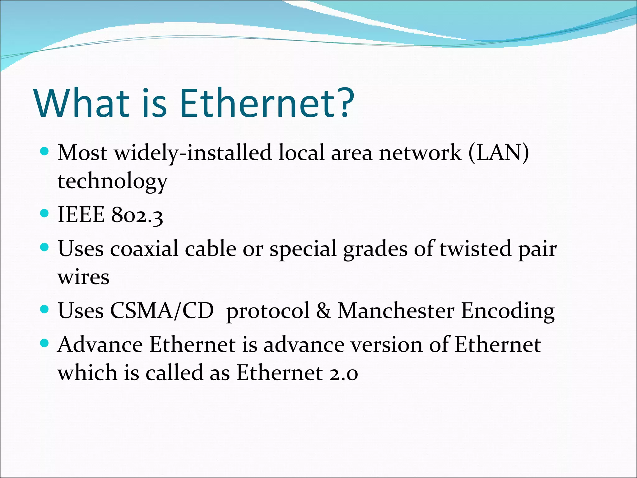
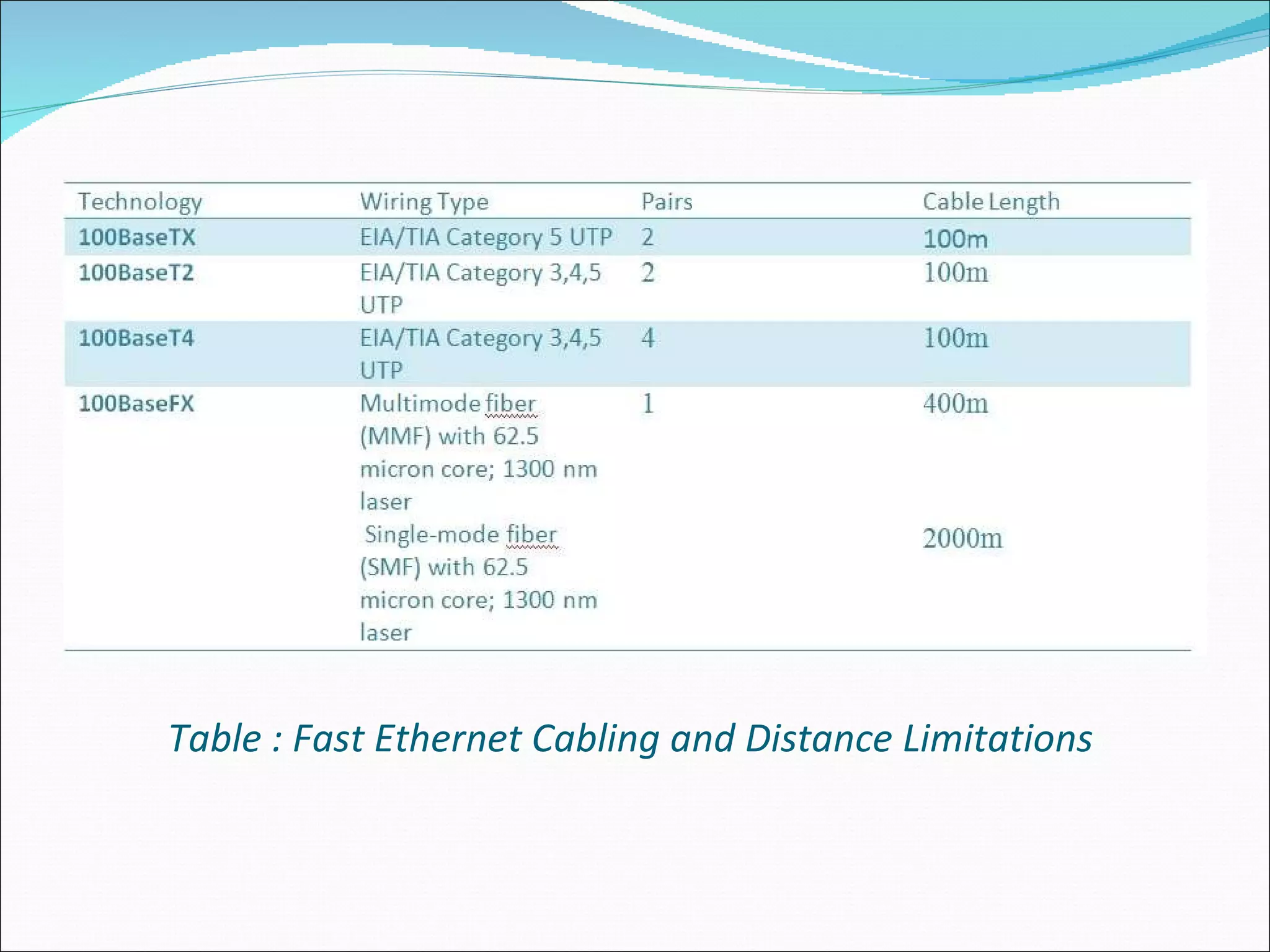
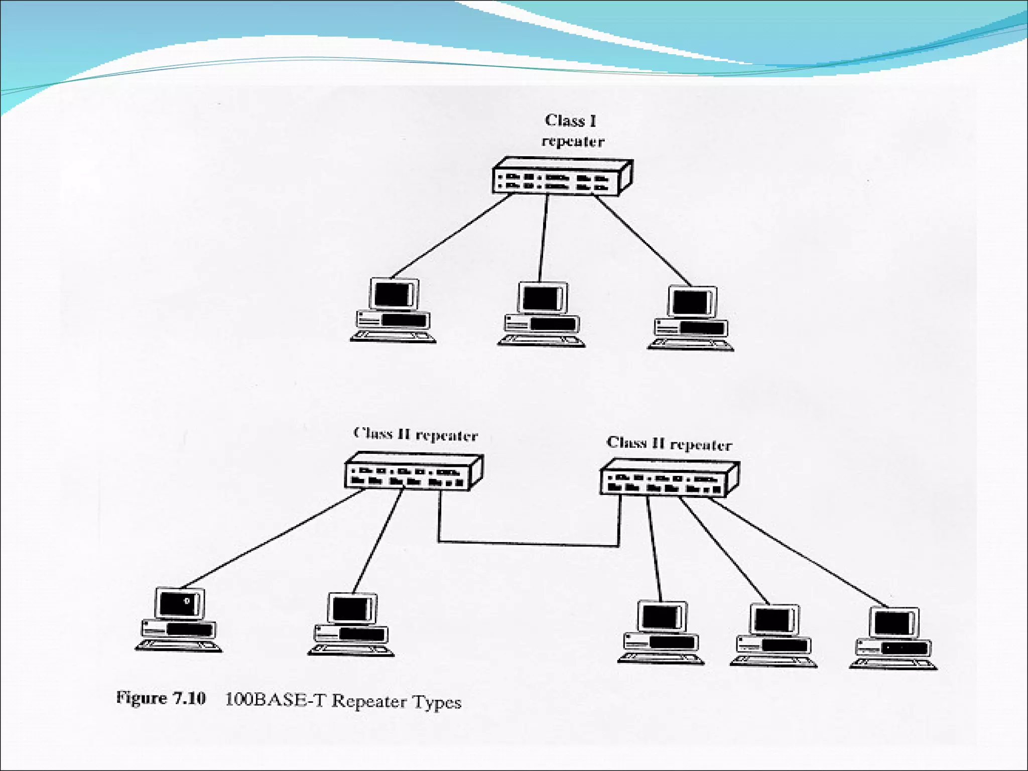
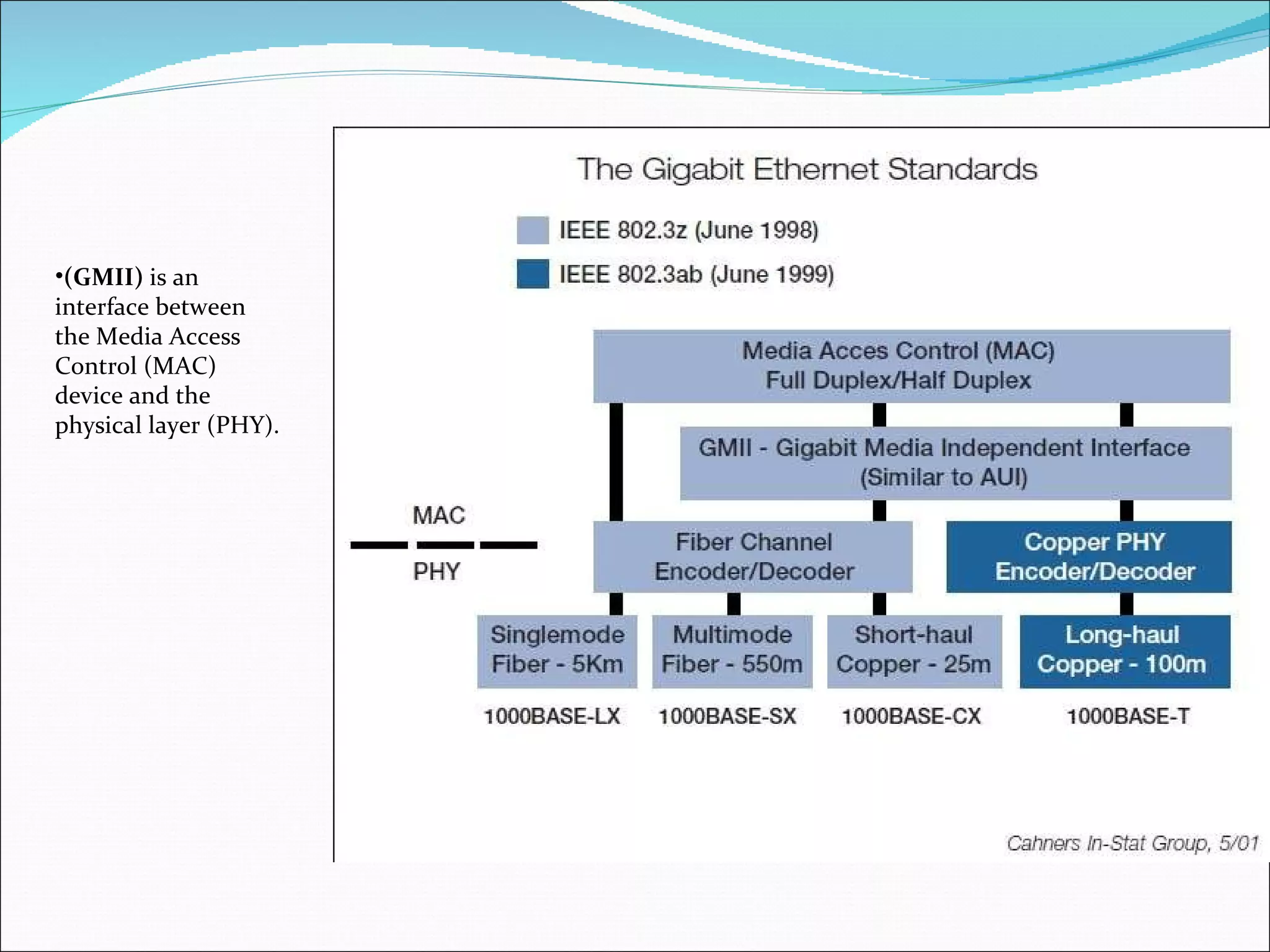
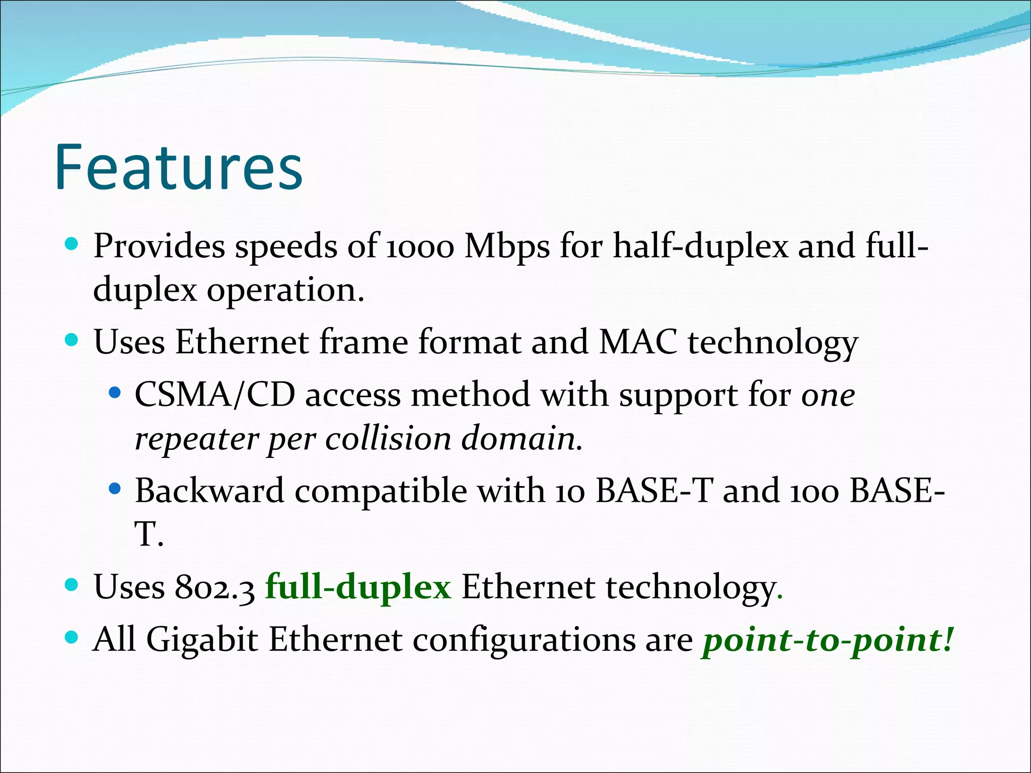
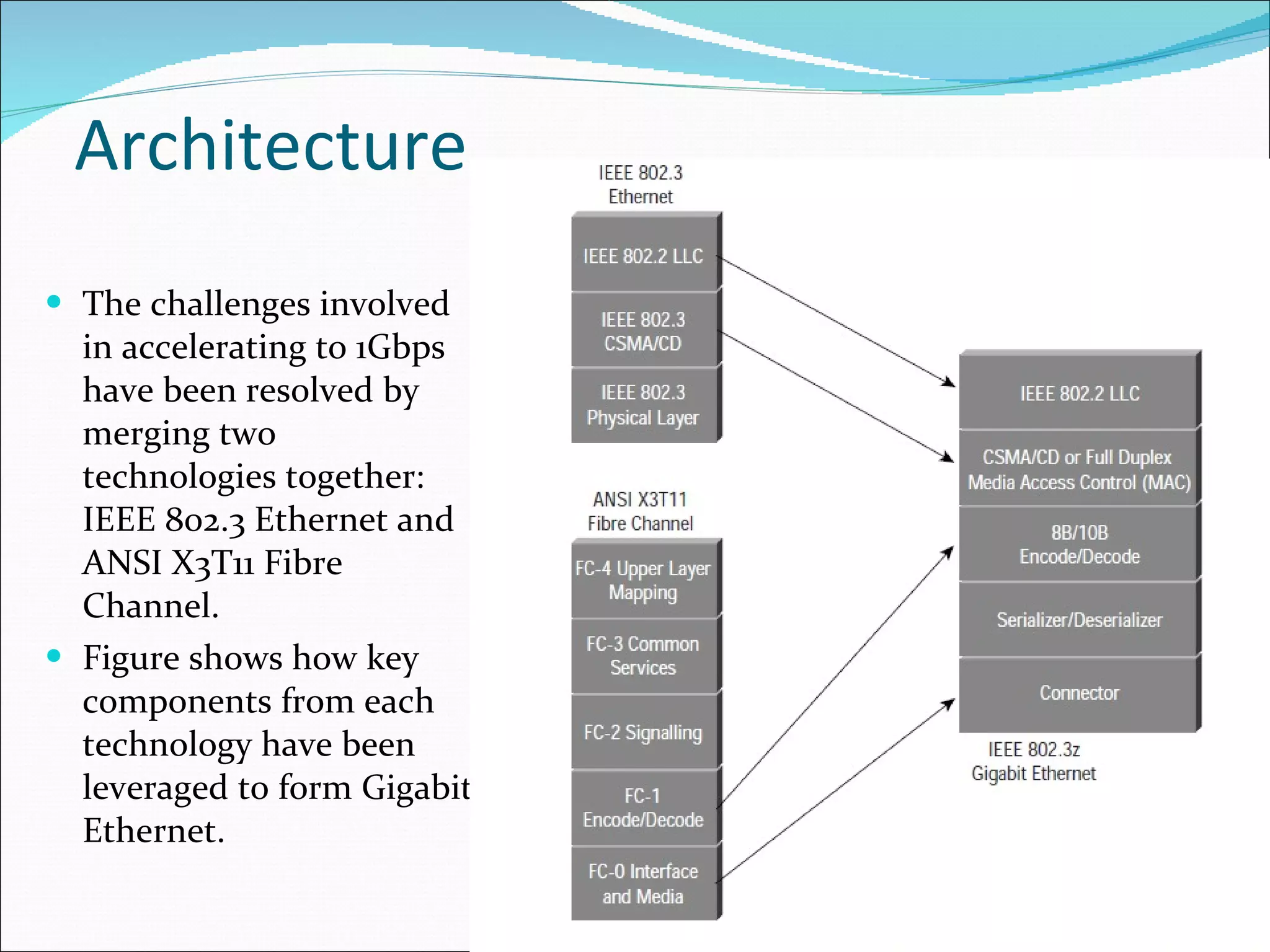
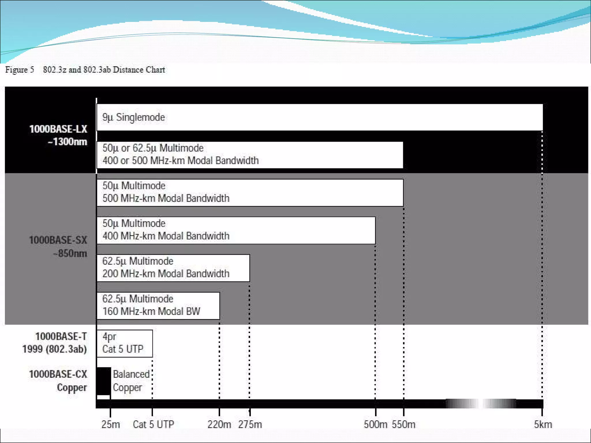
Ethernet is a widely used local area network technology that uses coaxial cable or twisted pair wires. Advanced versions include switched Ethernet, Fast Ethernet, and Gigabit Ethernet. Fast Ethernet operates at 100 Mbps using 4B/5B encoding. Gigabit Ethernet provides speeds of 1000 Mbps and maintains backward compatibility with previous Ethernet standards. It uses 8B/10B encoding and leverages technologies from Fibre Channel.

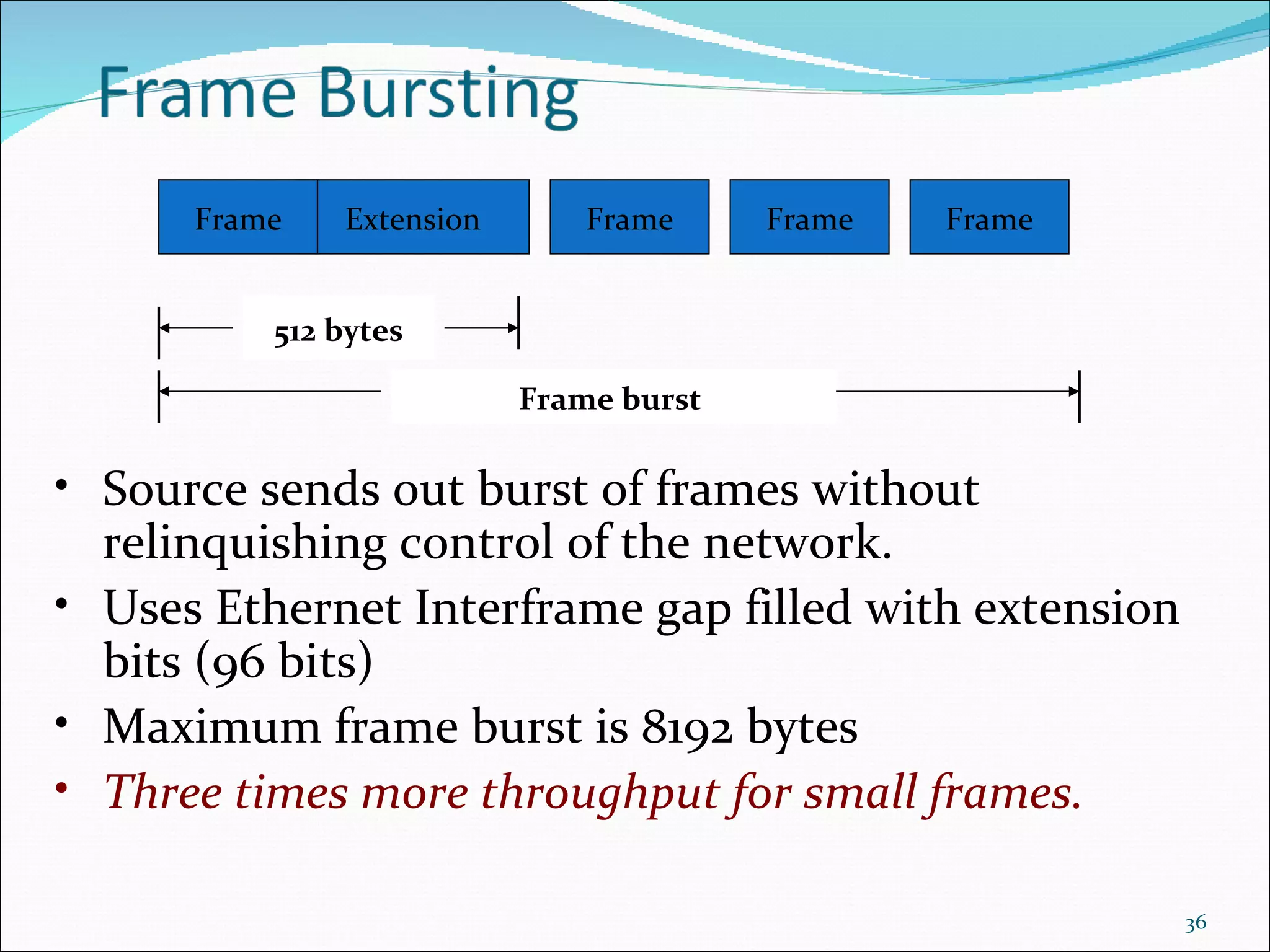
![Carrier Extention RRRRRRRRRRRRR Frame 512 bytes For 10BaseT : 2.5 km max; slot time = 64 bytes For 1000BaseT: 200 m max; slot time = 512 bytes Carrier Extension : continue transmitting control characters [R] to fill collision interval. This permits minimum 64-byte frame to be handled. Control characters discarded at destination.](https://image.slidesharecdn.com/advanceethernet-110817121102-phpapp01/75/Advance-ethernet-35-2048.jpg)


![Vibe Coding vs. Spec-Driven Development [Free Meetup]](https://cdn.slidesharecdn.com/ss_thumbnails/vibecodingvsspecdrivendevelopment-251209105622-43f455e7-thumbnail.jpg?width=640&height=640&fit=bounds)
