Download as PDF, PPTX


![Carbon dioxide and the greenhouse effect are necessary for Earth to survive. In
fact, if we had no greenhouse effect, our planet would have an average
temperature of –300C [source: UNEP]. However, human inventions like power
plants and transportation vehicles, which burn fossil fuels, release extra CO2 into
the air.](https://image.slidesharecdn.com/ccs3-150107031834-conversion-gate02/85/Carbon-Capture-Storage-10-320.jpg)


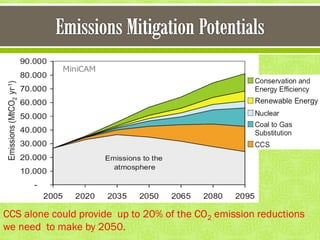


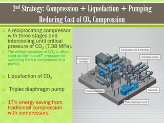


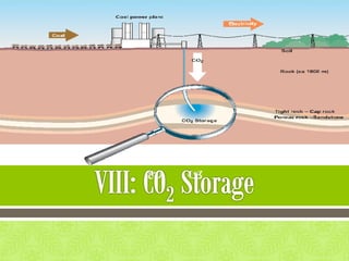


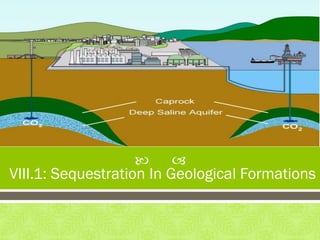


This document discusses carbon capture and storage (CCS) as a solution to reducing CO2 emissions and global warming. It covers various aspects of CCS including CO2 capture technologies like post-combustion capture using solvents, compression and transport of captured CO2, and geological storage options in saline aquifers or for enhanced oil recovery. The high cost of CCS technologies is also addressed.


