Download as PDF, PPTX
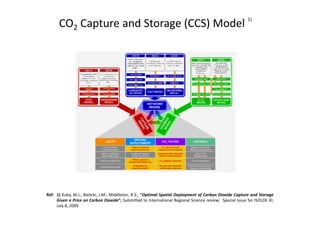
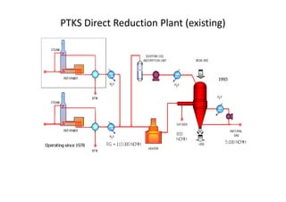

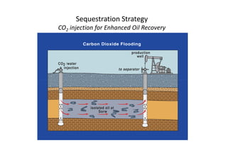
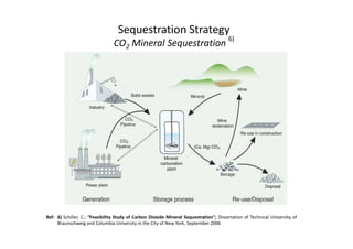
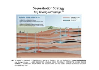
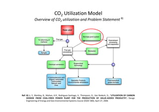
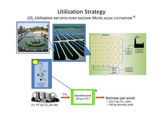
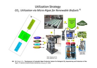
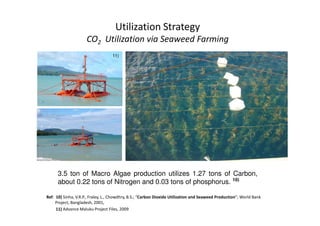
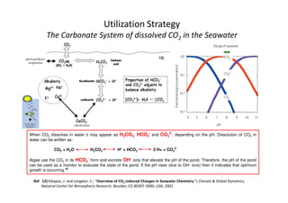
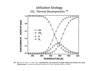
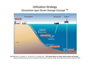
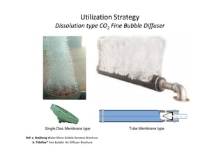

This document discusses strategies for carbon capture and storage as well as carbon dioxide utilization at PT Krakatau Steel in Indonesia. It analyzes models for CO2 capture from steel production and power plants, as well as sequestration methods like injection into geological formations or for enhanced oil recovery. Utilization strategies examined include microalgae cultivation for biofuels, seaweed farming to sequester carbon, and thermal decomposition of CO2 into synthesis gas. The document provides an overview of these various carbon reduction program options and references supporting literature.


