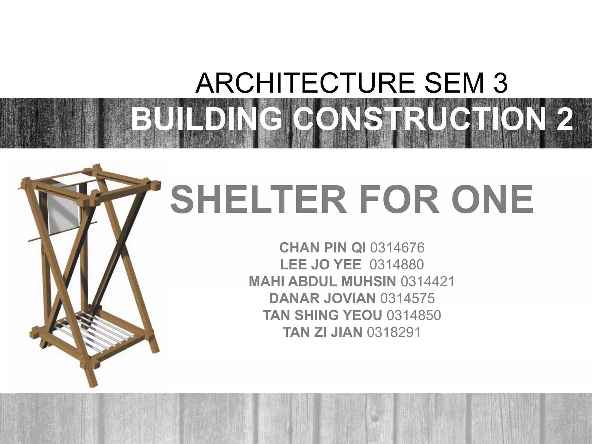
1) A group of students designed and built a portable shelter using recycled materials as part of an architecture class project.
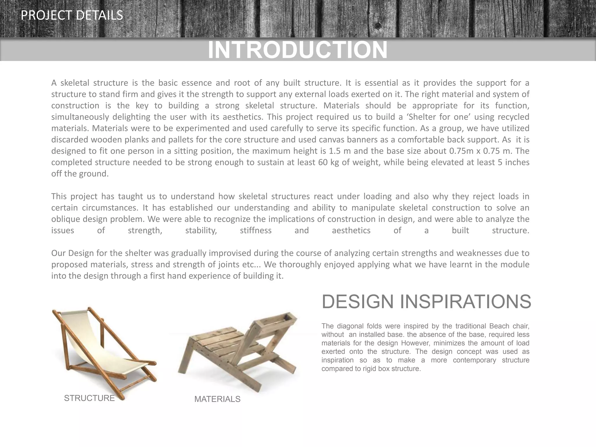
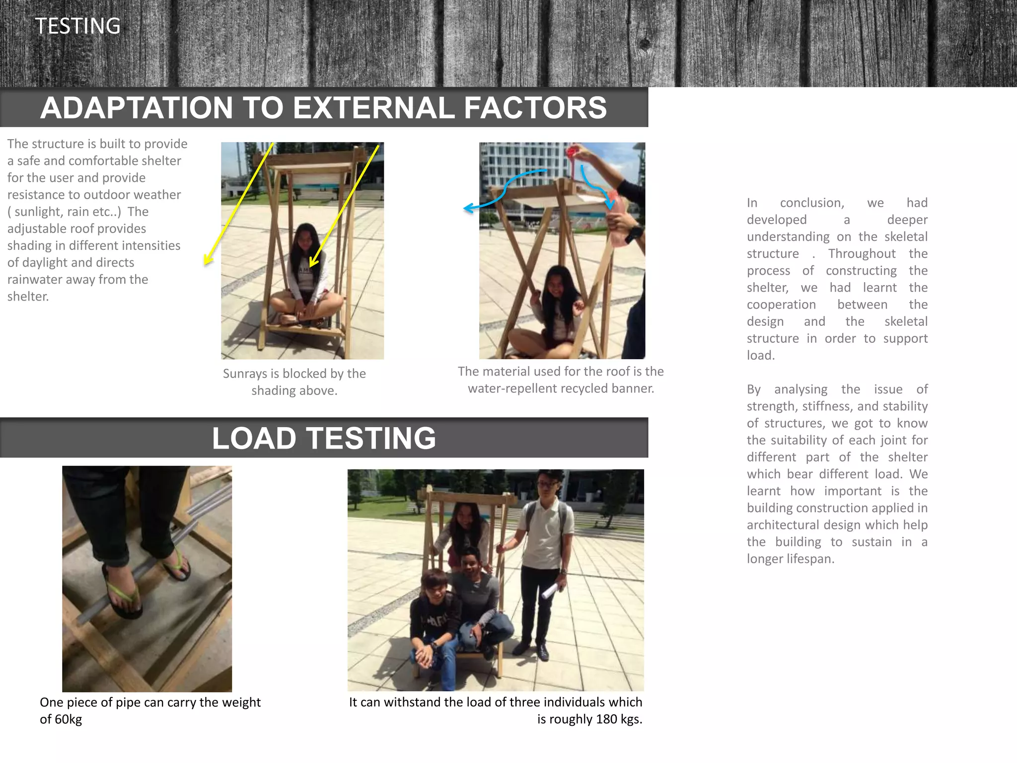
2) The shelter was designed to support a maximum weight of 60kg and protect one person in a sitting position from the elements.
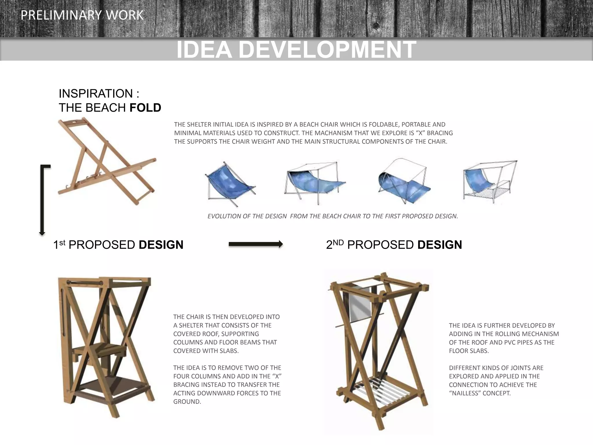
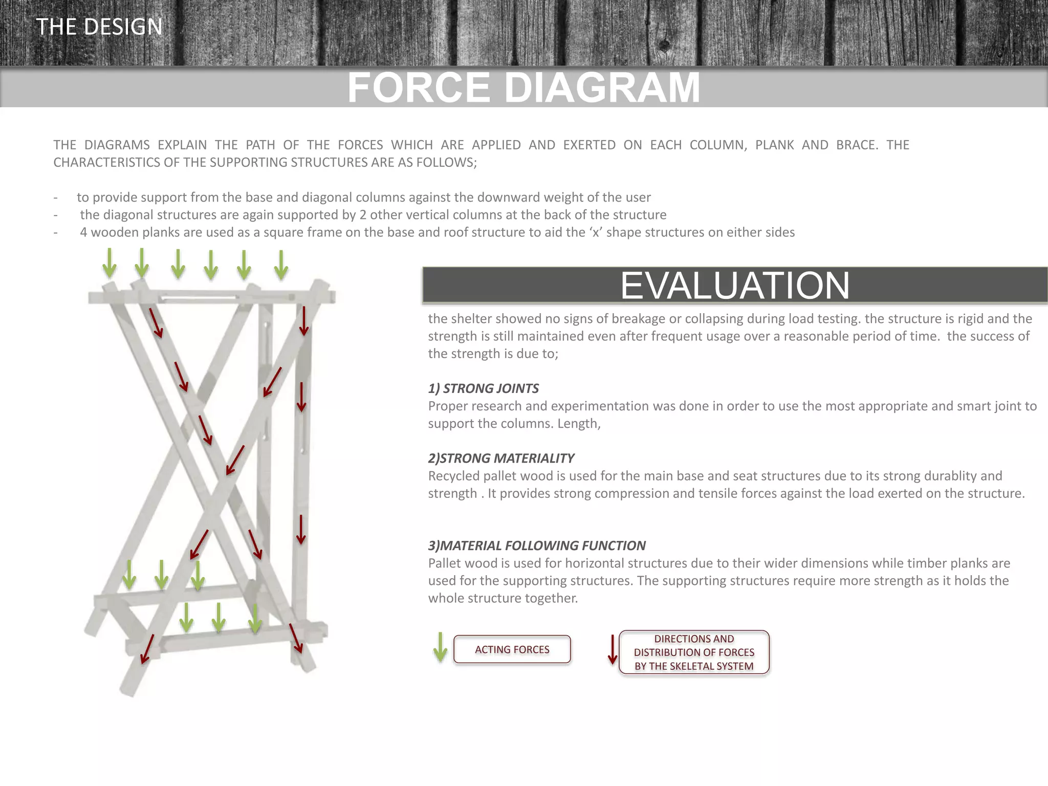
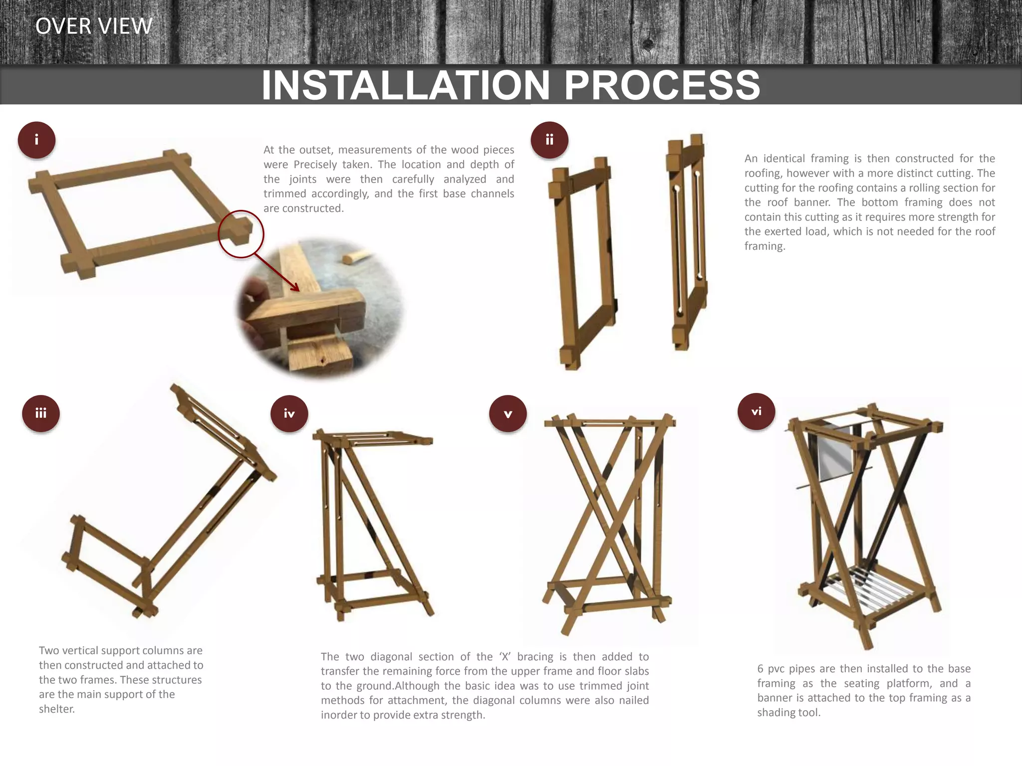
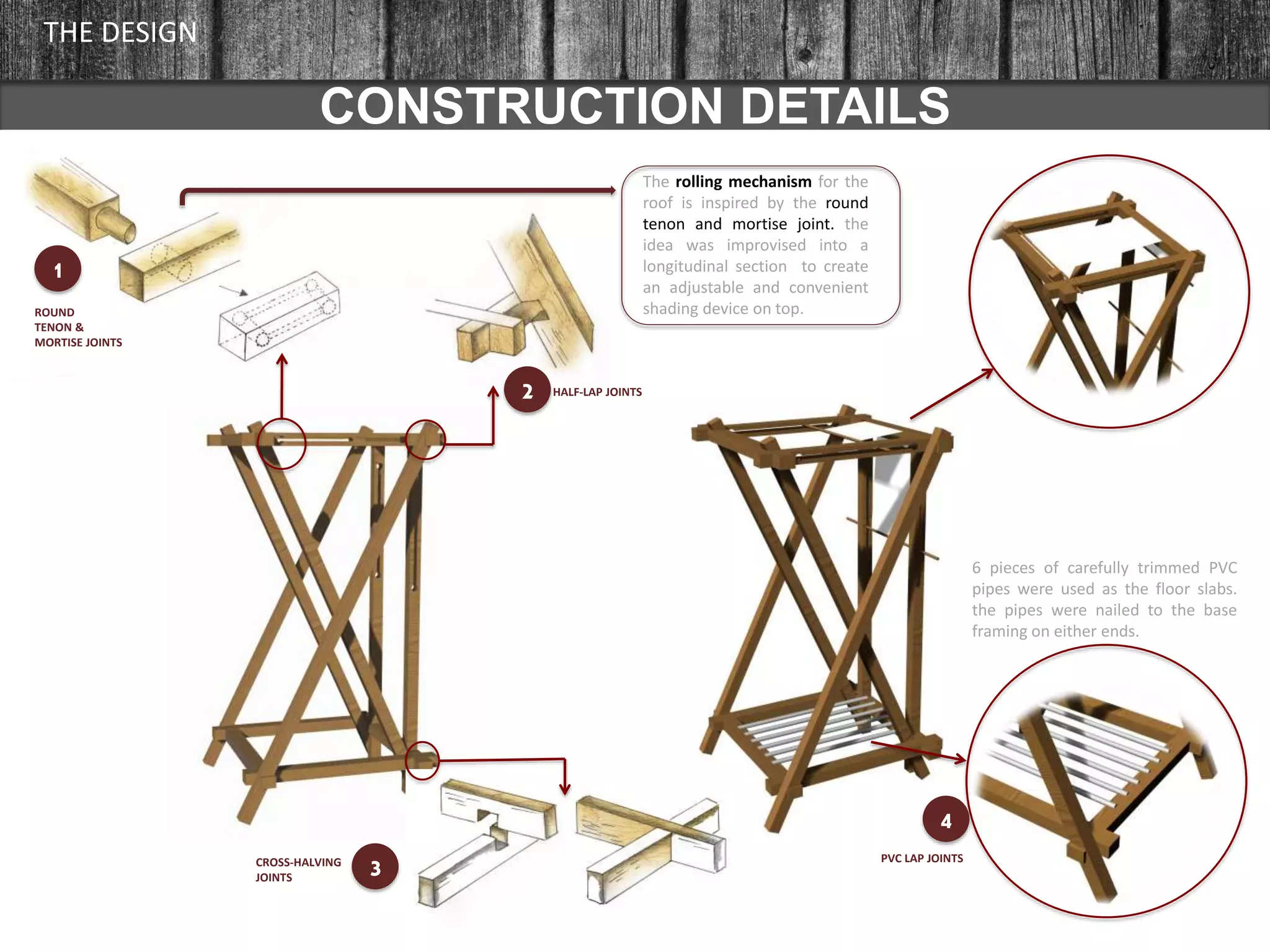
3) Through the process of designing, testing, and constructing the shelter, the students gained valuable insights into skeletal structures, appropriate material selection, and the relationship between construction and design.


![[BROCHURE] Italy Tour Project | @SlideON](https://cdn.slidesharecdn.com/ss_thumbnails/brochure8-251215152319-2805af68-thumbnail.jpg?width=640&height=640&fit=bounds)


