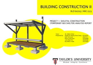
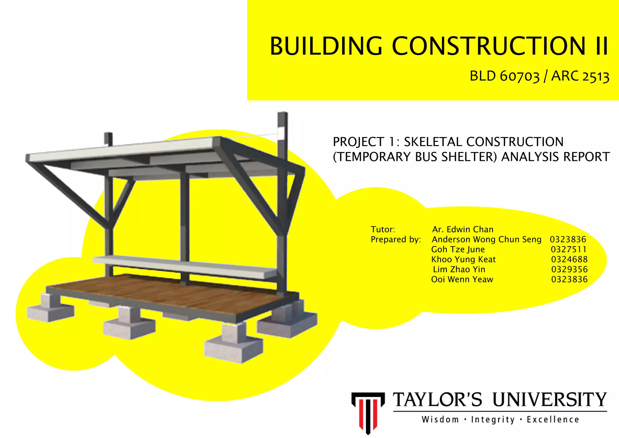
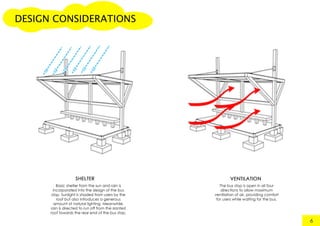
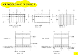
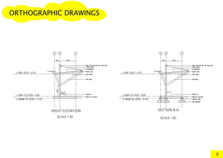
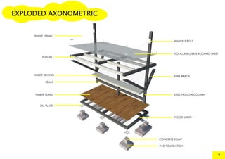
BUILDING CONSTRUCTION II
BLD 60703 / ARC 2513
PROJECT 1: SKELETAL CONSTRUCTION
(TEMPORARY BUS SHELTER) ANALYSIS REPORT
Tutor: Ar. Edwin Chan
Prepared by: Anderson Wong Chun Seng 0323836
Goh Tze June 0327511
Khoo Yung Keat 0324688
Lim Zhao Yin 0329356
Ooi Wenn Yeaw 0323836
Introduction
Design Concept
Massing
Design Development
Design Considerations
Orthogonal Drawings
Exploded AxonometricExploded Axonometric
Material Analysis
Construction Details
Construction Process
Loads & Forces
Final Outcome
Load Bearing Test
ConclusionConclusion
References
1
2
3
4
5-6
7-8
9
10-11
12-13
14
15
16
17
18
19
INDEX
INTRODUCTION
1
The objectives of this project are to create an
understanding of skeletal structure and its relevant
structural components, and how it reacts under
loading. In a group of five, we were assigned to
construct a temporary bus shelter to accommodate
5-6 users in the scale of 1:5, where the maximum
height and base area are 600mm and 400mm x
800mm respectively.800mm respectively.
We are required to demonstrate a convincing
understanding of how a skeletal construction works,
while taking factors such as form, frames, joints and
materials into account.
DESIGN CONCEPT
2
In relation with the ever-increasing urban
population in Malaysia, the design of our
temporary bus shelter is made to blend in
with the urban areas of our country, where
urbanites nowadays prioritize stability and
practicality in their buildings and structures.
Hence, our design tends to focus more on
construction and user needs.construction and user needs.
+
MASSING
3
The massing of the bus shelter is to be a combination
of two forms, which we have chosen a triangular prism
and a cuboid for our design.
The triangular prism is placed on top of the cuboid to
shape the form of the roof. Slanted flat roofs are
practical – they can reduce the velocity of falling
raindrops and direct the waterflow.
Triangular forms are also made to distribute the forcesTriangular forms are also made to distribute the forces
applied from one point to the other two equally.
Cuboid forms are typically used and easy to be
calculated in dimensions. Their right-angled form
maximizes the usage of space, as well as providing
stability and consistency in nature.
DESIGN DEVELOPMENT
The initial idea was to combine both
cuboid and triangular prism to
create a trapezoid form. The frame
at the back were slanted to create
a more interesting form of design.
However, difficult calculations were
needed to be made to determine
the degree of the slant. Hence, thethe degree of the slant. Hence, the
design was improvised.
4
The structure were simplified and
the front columns were removed,
maximizing the availability of
space. The columns at the back
were straightened but not entirely
to retain some degree of slant.
This design, yet provides sufficient
stability for the structure to hold.stability for the structure to hold.
The slanted flat roof was in risk of
collapsing.
As the design progresses, the
columns at the back were
straightened vertically, shifted
forward to the near middle and
pierced through the roof. Ten-
sion strings were attached from
the top of the columns to the
middle front of the roof to holdmiddle front of the roof to hold
it in place. Structural supports
for the back of the roof and
joists were added as well.
1 2 3
SCALE 1:50
SCALE 1:50 SCALE 1:50
7
ORTHOGRAPHIC DRAWINGS
SCALE 1:50 SCALE 1:50
8
EXPLODED AXONOMETRIC
SILL PLATE
STEEL HOLLOW COLUMN
CONCRETE STUMP
PAD FOUNDATION
PURLINS
TIMBER SEATING
TIMBER TILING
FLOOR JOISTS
9
KNEE BRACE
POLYCARBONATE ROOFING SHEET
KNUCKLE BOLT
BEAM
TENSILE STRING
All the floor beams and floor joists
are welded together.
The floor beam is welded with with
the sill plate.
The sill plate is screwed to the con-
crete stump.
FLOOR JOIST
FLOOR BEAM
CONCRETE STUMP
CONCRETE STUMP
PAD FOUNDATION
PAD FOUNDATION
ANCHOR ROD
TIMBER TILE
TIMBER TILE
SCREW
SQUARE HOLLOW SECTION
GROUND LEVEL
GROUND LEVEL
FINISH FLOOR LEVEL
FINISH FLOOR LEVEL
CONSTRUCTION DETAILS
12
Roof beam and rafter are
welded together using
knee brace and a tensile
string for support.
Metal plate is screwed with
the column to hold the
knuckle bolt. The knuckle
bolt is tightened with a ten-
sile string to hold the roof.
The seating steel plate
sits on the square
hollow section and is
welded to it.
A
B
C
A B C
SCREW
L-CHANNEL
TIMBER TILE
FINISH FLOOR
LEVEL
STEEL BAR
COLUMN
RAFTER
TENSILE STRING
KNUCKLE BOLT
KNEE BRACE
COLUMN
CONSTRUCTION DETAILS
13
FORCE AND LOAD
These are the components which bears the main
load of the structure. They also make up the general
framework of the bus shelter.
15
The secondary components functions as load
distributors as they distribute load evenly to the
primary components. This prevents the primary
components from being unevenly stressed.
The roof is supported by bracing to deal with tensile
force as an additional support while retaining the
head room.
1 2
3 4 The main load is transferred from the roof, which
then the active load from the roof is distributed
to the connecting bracing following to the
column.
CONCLUSION
Upon completion of this project, we were able
to grasp a more thorough understanding on
skeletal constructions and how each joint is
connected.
We have also acknowledged the need toWe have also acknowledged the need to
manipulate the construction of the structure to
accommodate with the issues on the strength
and stability of our design, the ability to
construct it, and how it reacts under forces,
stress and strain.
Material-wise, by understanding each of theMaterial-wise, by understanding each of the
chemical and physical properties, we were
able to select the most suitable materials to be
used, thus improving the practicality of our
temporary bus shelter. In the context of real life
working situations, the cost benefit analysis of
the selected materials should also be
considered.considered.
18

BCON II PROJECT 1

  • 1.
    BUILDING CONSTRUCTION II BLD60703 / ARC 2513 PROJECT 1: SKELETAL CONSTRUCTION (TEMPORARY BUS SHELTER) ANALYSIS REPORT Tutor: Ar. Edwin Chan Prepared by: Anderson Wong Chun Seng 0323836 Goh Tze June 0327511 Khoo Yung Keat 0324688 Lim Zhao Yin 0329356 Ooi Wenn Yeaw 0323836
  • 2.
    Introduction Design Concept Massing Design Development DesignConsiderations Orthogonal Drawings Exploded AxonometricExploded Axonometric Material Analysis Construction Details Construction Process Loads & Forces Final Outcome Load Bearing Test ConclusionConclusion References 1 2 3 4 5-6 7-8 9 10-11 12-13 14 15 16 17 18 19 INDEX
  • 3.
    INTRODUCTION 1 The objectives ofthis project are to create an understanding of skeletal structure and its relevant structural components, and how it reacts under loading. In a group of five, we were assigned to construct a temporary bus shelter to accommodate 5-6 users in the scale of 1:5, where the maximum height and base area are 600mm and 400mm x 800mm respectively.800mm respectively. We are required to demonstrate a convincing understanding of how a skeletal construction works, while taking factors such as form, frames, joints and materials into account.
  • 4.
    DESIGN CONCEPT 2 In relationwith the ever-increasing urban population in Malaysia, the design of our temporary bus shelter is made to blend in with the urban areas of our country, where urbanites nowadays prioritize stability and practicality in their buildings and structures. Hence, our design tends to focus more on construction and user needs.construction and user needs.
  • 5.
    + MASSING 3 The massing ofthe bus shelter is to be a combination of two forms, which we have chosen a triangular prism and a cuboid for our design. The triangular prism is placed on top of the cuboid to shape the form of the roof. Slanted flat roofs are practical – they can reduce the velocity of falling raindrops and direct the waterflow. Triangular forms are also made to distribute the forcesTriangular forms are also made to distribute the forces applied from one point to the other two equally. Cuboid forms are typically used and easy to be calculated in dimensions. Their right-angled form maximizes the usage of space, as well as providing stability and consistency in nature.
  • 6.
    DESIGN DEVELOPMENT The initialidea was to combine both cuboid and triangular prism to create a trapezoid form. The frame at the back were slanted to create a more interesting form of design. However, difficult calculations were needed to be made to determine the degree of the slant. Hence, thethe degree of the slant. Hence, the design was improvised. 4 The structure were simplified and the front columns were removed, maximizing the availability of space. The columns at the back were straightened but not entirely to retain some degree of slant. This design, yet provides sufficient stability for the structure to hold.stability for the structure to hold. The slanted flat roof was in risk of collapsing. As the design progresses, the columns at the back were straightened vertically, shifted forward to the near middle and pierced through the roof. Ten- sion strings were attached from the top of the columns to the middle front of the roof to holdmiddle front of the roof to hold it in place. Structural supports for the back of the roof and joists were added as well. 1 2 3
  • 9.
    SCALE 1:50 SCALE 1:50SCALE 1:50 SCALE 1:50 SCALE 1:50 7 ORTHOGRAPHIC DRAWINGS
  • 10.
  • 11.
    EXPLODED AXONOMETRIC SILL PLATE STEELHOLLOW COLUMN CONCRETE STUMP PAD FOUNDATION PURLINS TIMBER SEATING TIMBER TILING FLOOR JOISTS 9 KNEE BRACE POLYCARBONATE ROOFING SHEET KNUCKLE BOLT BEAM TENSILE STRING
  • 14.
    All the floorbeams and floor joists are welded together. The floor beam is welded with with the sill plate. The sill plate is screwed to the con- crete stump. FLOOR JOIST FLOOR BEAM CONCRETE STUMP CONCRETE STUMP PAD FOUNDATION PAD FOUNDATION ANCHOR ROD TIMBER TILE TIMBER TILE SCREW SQUARE HOLLOW SECTION GROUND LEVEL GROUND LEVEL FINISH FLOOR LEVEL FINISH FLOOR LEVEL CONSTRUCTION DETAILS 12
  • 15.
    Roof beam andrafter are welded together using knee brace and a tensile string for support. Metal plate is screwed with the column to hold the knuckle bolt. The knuckle bolt is tightened with a ten- sile string to hold the roof. The seating steel plate sits on the square hollow section and is welded to it. A B C A B C SCREW L-CHANNEL TIMBER TILE FINISH FLOOR LEVEL STEEL BAR COLUMN RAFTER TENSILE STRING KNUCKLE BOLT KNEE BRACE COLUMN CONSTRUCTION DETAILS 13
  • 16.
    FORCE AND LOAD Theseare the components which bears the main load of the structure. They also make up the general framework of the bus shelter. 15 The secondary components functions as load distributors as they distribute load evenly to the primary components. This prevents the primary components from being unevenly stressed. The roof is supported by bracing to deal with tensile force as an additional support while retaining the head room. 1 2 3 4 The main load is transferred from the roof, which then the active load from the roof is distributed to the connecting bracing following to the column.
  • 17.
    CONCLUSION Upon completion ofthis project, we were able to grasp a more thorough understanding on skeletal constructions and how each joint is connected. We have also acknowledged the need toWe have also acknowledged the need to manipulate the construction of the structure to accommodate with the issues on the strength and stability of our design, the ability to construct it, and how it reacts under forces, stress and strain. Material-wise, by understanding each of theMaterial-wise, by understanding each of the chemical and physical properties, we were able to select the most suitable materials to be used, thus improving the practicality of our temporary bus shelter. In the context of real life working situations, the cost benefit analysis of the selected materials should also be considered.considered. 18