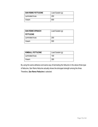
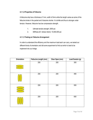
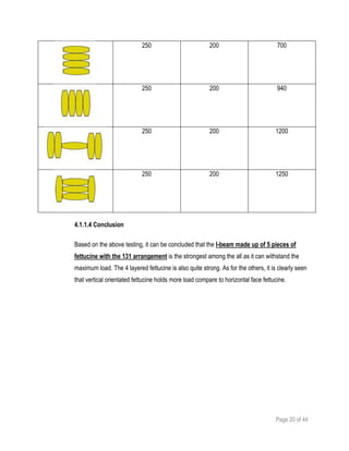
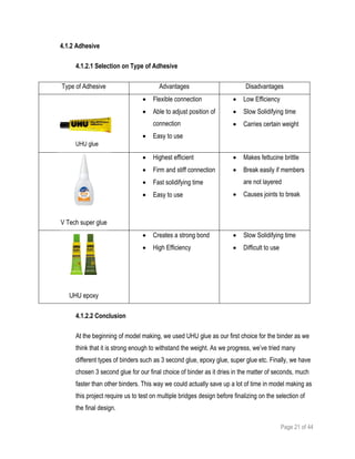
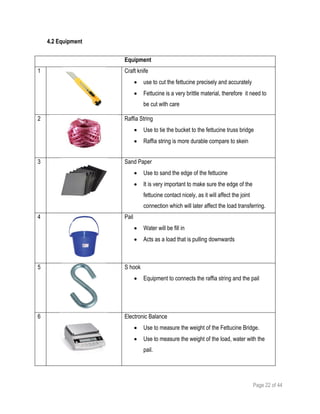
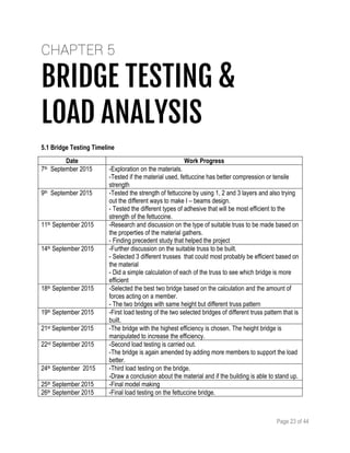
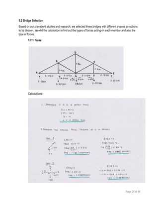
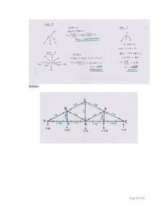
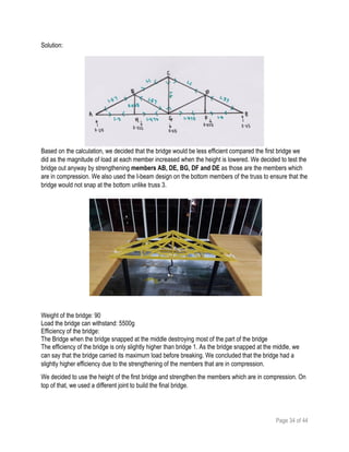
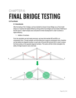
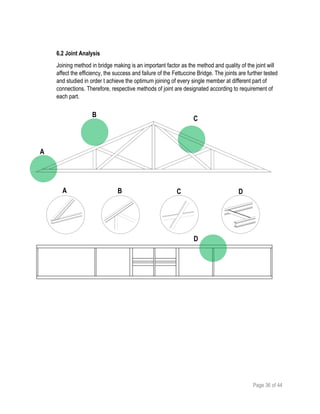
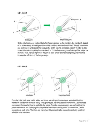
FETTUCCINE
TRUSS
BRIDGEPROJECT ONE
ARC 2523 BUILDING STRUCTURES
SCHOOL OF SCIENCE, ARCHITECTURE AND BUILDING DESIGN
TUTOR: MISS ANN SEE PENG
CHOONG LAI MUN
SOO XIAO WEN
CHAN BOON HAW
JOLENE HOR
CRSYTALLINA ALECIA
LEE JO YEE
0313575
0314130
0313667
0313751
0318742
0314880
Page 2 of 44
1.0 Introduction
1.1 Project Intention and research
1.2 Aim of the Project
1.3 Report Overview
1.4 Learning Outcomes
2.0 Methodology
2.1 Precedent Study
2.2 Materials and Equipment Testing
2.3 Model making
2.4 Structural Analysis
2.5 Bridge Efficiency Calculation
3.0 Precedent Study
3.1 Background History
3.2 Structure
3.3 Joints
4.0 Materials and Equipment
4.1 Materials
4.2 Equipment
5.0 Bridge Testing and Load Analysis
5.1 Timeline
5.2 First Bridge
5.3 Second Bridge
6.0 Final Bridge
6.1 Amendments
6.2 Final model making
6.3 joint analysis
6.4 final bridge testing and load analysis
6.5 calculations
6.6 design solution
7.0 Conclusion
8.0 Appendix
2.1 CASE STUDY 1 – JOLENE HOR WEI
2.2 CASE STUDY 2 – CHOONG LAI MUN
2.3 CASE STUDY 3 – LEE JO YEE
2.4 CASE STUDY 4 – CRSYTALLINA ALECIA
2.5 CASE STUDY 5 – SOO XIAO WEN
2.6 CASE STUDY 6 – CHAN BOON HAW
9.0 References
Page 3 of 44
CHAPTER 1
INTRODUCTION1.0 Introduction
1.1 Project Intention and Requirement
Distributed into a group of 5 members, this project requires us to build and design a truss fettuccine
bridge. This fettuccine bridge must be very efficient, and to do so it has to withstand the most weight
from the least material used, given that it has a clear span of 350mm and a maximum weight of 80g.
We are required to investigate and understand the compressive and tensile strength of construction
materials, with the uses of fettuccine. There are many types of truss bridge, and this is why research
are required in order for us to carry out precedent studies. Apart from the types of truss bridges, the
types of binders are also tested in order for us to find out the best one for the bridge. As the project
progresses, we are able to identify the best type of truss system and how to strengthen it wisely without
it having too much weight so the load distribution of the entire bridge will be even.
1.2 Aim of the Project
The aim of this fettuccine truss bridge project is to develop student’s understanding of tension and
compressive strength of construction materials and also the understanding of force distribution in a
truss. Other than that, this project aims students to design a perfect truss bridge which fulfills the
aesthetic value by using minimal construction material.
Page 4 of 44
1.3 Report Overview
The report started off with a precedent study on a truss bridge. The amount of member will be recorded
and the load distribution of the bridge will be analyzed. As we progress, different patterns and designs
of the bridge will be tested out and recorded in order for us to find out the best design for the final
bridge. Many tests were carried out and the development was recorded and improved once the testing
bridge reaches its limit. Eventually through all these tests, the efficiency of the bridge will increase.
Analysis of the strength of the bridge in each tests and the reason of failure are also recorded. The end
of the report will be the calculations of the individual case studies.
1.4 Learning Outcomes
By the end of this project, students are able to:
 Evaluate, explore and improve attributes of construction materials.
 Explore and apply understanding of load distribution in a truss.
 Evaluate and identify tension and compression members in a truss structure.
 Explore different arrangement of members in a truss structure.
Page 5 of 44
CHAPTER 2
METHODOLOGY2.0 Methodology
We have carried out following methods in the process of researching and building a suitable truss bridge:
2.1 Precedent Study
By looking through precedent studies, we will have a better understanding on the types of trusses
available. We had chosen Waddell A Truss Bridge as our case study for this project. This Waddell A
Truss Bridge has inspired us for our final fettucine bridge in terms of design and truss
member arrangement. Further exploration and findings will be elaborated in the Precedent
Study section later.
2.2 Materials and Equipment Testing
Different brands and types of fettuccine were experimented to examine its tension and compressive
strength before deciding to select a specific brand to proceed with our truss bridge. ”San Remo” is the
finalized brand of fettucine that we have selected as it is the strongest comparing to other brands. We
had also experimented and observe how various types of adhesive are being used and how they affect
the joints. We settled on super glue at the end.
Page 6 of 44
2.3 Model Making
The model making process was an on-going process as we had to keep revising and improving the
Fettuccine Bridge after each load testing to achieve higher efficiency. We started with three different
designs and tested the bridges to find out which one is strongest. A total of 8 bridges with various
designs were built and experimented throughout this project. After each test, the strength of the bridge
is maintained and the weakness is eliminated and further developed.
1st step: Understanding the properties of the Fettuccine
2nd step: Choosing the correct adhesive agent
3rd step: Put the Bridge Truss Design into Scaled Drawings in Autocad and print out to experiement
4th step: Arrange the Fettucine position base on its strength and weakness.
5th step: Model Testing
2.4 Structural Analysis
Structural Analysis is the determination on the effects of load on the Fettuccine Bridge and its members
by calculation.
2.5 Bridge Efficiency Calculation
The efficiency of the bridge tested is calculated using the formula:
Efficiency, E = (Maximum Load)2
Weight of Bridge
Page 7 of 44
CHAPTER 3
PRECEDENT STUDY3.0 Precedent Study
Waddel “A” Truss Bridge
3.1 Background History
The Waddell “A” Truss Bridge is currently located in English Landing Park, Parkville, Platte County,
Missouri. It was originally built as a railroad bridge across Lin Branch Creek in the vicinity of Trimble,
Clinton County, Missouri.
Today, it crosses Rush Creek carrying a pedestrian path between a day-use recreational area and two
isolated ball fields. In a shape of a triangle, steel, and through-truss, this bridge is approximately 100
feet long and 40 feet high. It rests on two concrete abutments and is composed of pin-connected
riveted units.
Page 8 of 44
In 1980, the bridge was disassembled and stored for 7 years by the U.S. Army Corps of Engineers,
while waiting for a suitable location and responsible owner. Regardless of being relocated, the bridge
retains its integrity of design as drawn by its creator, John Alexander Low Waddell. The bridge was
reassembled using the same high standards as originally specified by the designers.
3.2 Structure
The table below shows some basic dimensions of the bridge:
Total Length 100.0 ft. / 30.48 meter
Height Above River
Deck Width 16.0 ft.
Height 12 meters
Distance between each truss
member
Around 5.2 meters
The Waddell “A” Truss Bridge is a triangular shaped steel through-truss bridge. It is a single-span, four-
panel, pin-connected steel truss bridge, resting on two concrete supports linked by pin-connected riveted
units.
The trusses are known as “A” trusses because of its “A” shape, greatly resembling the king-post roof
trusses used typically in houses, but its post are usually in tension. X-bracing can be found in between two
trusses to provide sideway stability.
The compression members of the trusses are shop-riveted built-up sections, it is made out of channels,
angles, and plates; the tension members however are made out of pairs of eye-bars.
The shape was actually caused by the top bracing and reduced in the amount of steel used in constructing
the bridge.
The bottom chord is separated into four sections, 7.6 meters by 5 meters, sway-braced by angle braces
and supporting a pair of girder stringers which are, in turn, angle braced. The floor system consists of
cross-braced, built-up timber floor beams and stringers.
Page 9 of 44
GENERAL VIEW OF "A" TRUSS FROM SIDE SHOWING ABUTMENT
BRIDGE DATAPLATE
Page 10 of 44
GENERAL VIEW OF “A” TRUSS FROM RIVER BANK
“BARREL SHOT” OF THE BRIDGE
Page 11 of 44
IDENTIFICATION OF MEMBERS IN WADDELL “A” TRUSS BRIDGE
3.3 Joints
In this section, we explored into the members of the bridge and their joining parts. From there, we have
developed an understanding of basic joining and stabilizing which further inspired us in designing the
final bridge form.
Page 12 of 44
Cross-Bracing
MISSOURI BRIDGE ENGINEERING ELEVATION DRAWING BY JOHN ALEXANDER WADDELL
*Full resolution refer to appendix
VIEW OF THE LATERAL CROSS BRACING
Page 13 of 44
Gusset Joint
CONNECTION MEMBERS AND
GUSSET JOINTS CAN BE FOUND
AT THE TOP CHORD.
DETAIL DRAWING OF THE TOP CHORD OF THE BRIDGE
*Full resolution refer to appendix
Page 14 of 44
Pint Joints
CONNECTED BY PIN JOINT
DETAILED VIEW OF THE COLUMN AND PIN JOINT
Page 15 of 44
DETAILS OF THE TRUSS CONNECTIONS AND MEMBERS BY JOHN ALEXANDER
*Full resolution refer to appendix
Page 16 of 44
Cross Bracing below the Bridge
DETAIL VIEW OF THE FLOOR BEAMS AND BOTTOM CHORD LATERAL BRACING
DETAIL VIEW OF LATERAL CROSS BRACING UNDER THE BRIDGE
Page 17 of 44
CHAPTER 4
MATERIALS & EQUIPMENT4.0 Materials and Equipment
4.1 Materials
4.1.1 Fettucine
4.1.1.1 Selection of Type of Fettucine
Before constructing the final fettucine bridge material, we bought a few type of fettucine to test
out the strongest fettucine to be used. We had the San Rimo normal fettucine, San Rimo
spinach fettucine, and the Kimball fettucine. We carried out a few test using this three kind
of fettucine and the following are the result.
San Rimo Spinach Fettucine
San Rimo Fettucine
Kimball Fettucine
Page 18 of 44
SAN REMO FETTUCINE Load Sustain (g)
Laminated truss 250
I-beam 600
SAN REMO SPINACH
FETTUCINE
Load Sustain (g)
Laminated truss 200
I-beam 500
KIMBALL FETTUCINE Load Sustain (g)
Laminated truss 100
I-beam 300
By using the same adhesive and same way of laminating the fettucine in the above three type
of fettucine, San Remo fettucine actually shows the strongest strength among the three.
Therefore, San Remo Fettucine is selected.
Page 19 of 44
4.1.1.2 Properties of Fettucine
A fettucine strip has a thickness of 1mm, width of 5mm while the length varies as some of the
fettucine broke in the packet and it became shorter. It is brittle and thus is stronger under
tension. However, fettucine has low compression strength.
1. Ultimate tensile strength: 2000 psi
2. Stiffness (E= stress/ strain): 10,000,000 psi
4.1.1.3 Testing on Fettucine Arrangement
In order to understand the efficiency and the maximum load each can carry, we tested out
different kinds of orientation and did some experiment to find out which is best to be
implement into our bridge.
Orientation Fettucine Length (mm) Clear Span (mm) Load Sustain (g)
250 200 300
250 200 480
250 200 500
250 200 650
Page 20 of 44
250 200 700
250 200 940
250 200 1200
250 200 1250
4.1.1.4 Conclusion
Based on the above testing, it can be concluded that the I-beam made up of 5 pieces of
fettucine with the 131 arrangement is the strongest among the all as it can withstand the
maximum load. The 4 layered fettucine is also quite strong. As for the others, it is clearly seen
that vertical orientated fettucine holds more load compare to horizontal face fettucine.
Page 21 of 44
4.1.2 Adhesive
4.1.2.1 Selection on Type of Adhesive
Type of Adhesive Advantages Disadvantages
 Flexible connection
 Able to adjust position of
connection
 Easy to use
 Low Efficiency
 Slow Solidifying time
 Carries certain weight
V Tech super glue
 Highest efficient
 Firm and stiff connection
 Fast solidifying time
 Easy to use
 Makes fettucine brittle
 Break easily if members
are not layered
 Causes joints to break
UHU epoxy
 Creates a strong bond
 High Efficiency
 Slow Solidifying time
 Difficult to use
4.1.2.2 Conclusion
At the beginning of model making, we used UHU glue as our first choice for the binder as we
think that it is strong enough to withstand the weight. As we progress, we’ve tried many
different types of binders such as 3 second glue, epoxy glue, super glue etc. Finally, we have
chosen 3 second glue for our final choice of binder as it dries in the matter of seconds, much
faster than other binders. This way we could actually save up a lot of time in model making as
this project require us to test on multiple bridges design before finalizing on the selection of
the final design.
UHU glue
Page 22 of 44
4.2 Equipment
Equipment
1 Craft knife
 use to cut the fettucine precisely and accurately
 Fettucine is a very brittle material, therefore it need to
be cut with care
2 Raffia String
 Use to tie the bucket to the fettucine truss bridge
 Raffia string is more durable compare to skein
3 Sand Paper
 Use to sand the edge of the fettucine
 It is very important to make sure the edge of the
fettucine contact nicely, as it will affect the joint
connection which will later affect the load transferring.
4 Pail
 Water will be fill in
 Acts as a load that is pulling downwards
5 S hook
 Equipment to connects the raffia string and the pail
6 Electronic Balance
 Use to measure the weight of the Fettucine Bridge.
 Use to measure the weight of the load, water with the
pail.
Page 23 of 44
CHAPTER 5
BRIDGE TESTING &
LOAD ANALYSIS
5.1 Bridge Testing Timeline
Date Work Progress
7th September 2015 -Exploration on the materials.
-Tested if the material used, fettuccine has better compression or tensile
strength
9th September 2015 -Tested the strength of fettuccine by using 1, 2 and 3 layers and also trying
out the different ways to make I – beams design.
- Tested the different types of adhesive that will be most efficient to the
strength of the fettuccine.
11th September 2015 -Research and discussion on the type of suitable truss to be made based on
the properties of the material gathers.
- Finding precedent study that helped the project
14th September 2015 -Further discussion on the suitable truss to be built.
- Selected 3 different trusses that could most probably be efficient based on
the material
- Did a simple calculation of each of the truss to see which bridge is more
efficient
18th September 2015 -Selected the best two bridge based on the calculation and the amount of
forces acting on a member.
- The two bridges with same height but different truss pattern
19th September 2015 -First load testing of the two selected bridges of different truss pattern that is
built.
21st September 2015 -The bridge with the highest efficiency is chosen. The height bridge is
manipulated to increase the efficiency.
22rd September 2015 -Second load testing is carried out.
-The bridge is again amended by adding more members to support the load
better.
24th September 2015 -Third load testing on the bridge.
-Draw a conclusion about the material and if the building is able to stand up.
25th September 2015 -Final model making
26th September 2015 -Final load testing on the fettuccine bridge.
Page 24 of 44
5.2 Bridge Selection
Based on our precedent studies and research, we selected three bridges with different trusses as options
to be chosen. We did the calculation to find out the types of forces acting on each member and also the
type of forces.
5.2.1 Truss
Calculations:
Page 25 of 44
Solution:
Page 26 of 44
2.5.2 Truss 2
Calculations:
Page 27 of 44
Solution:
Page 28 of 44
5.2.3 Truss 3
Calculation:
Page 29 of 44
Page 30 of 44
Solution:
5.4 Analysis of truss
The height and the width of the truss remains the same as the design of the truss is manipulated.
This is so that we can analyze the trusses easily. Based on the calculations, truss 1 has only 5
members out of the 18 members that are in compression while truss 2 and 3 has 8 members out of
the 21 members and 8 out of 29 members respectively. Members which are in compression at
truss 2 have a higher magnitude as compared to truss 1 and truss 3. As fettuccine has a higher
resistant to tension works well in tension, we can conclude that truss 1 and truss 3 are the better
option of the three. From this conclusion, we selected truss 1 and truss 3 to be built into a bridge to
be tested.
TRUSS 1 TRUSS 2
TRUSS 3
Page 31 of 44
5.5 Testing of bridges
5.5.1 Bridge 1
Weight of the bridge: 110g
Load the bridge can withstand: 1470g
Efficiency of the bridge: The Bridge failed due to the poor workmanship as it cracked at the
joints.
5.5.2 Bridge 2
Weight of the bridge: 112g
Load the bridge can withstand: 1350g
Efficiency of the bridge:
The Bridge failed when one of the bottom members snapped. This means that the bridge
bared its maximum load.
Page 32 of 44
5.6 Analyzing the Bridges
After testing the bridges, Bridge 1 has a higher efficiency. As bridge 1 failed when one of the joint
was dislocated due to the poor workmanship, we can assume that should the workmanship be
better, the bridge would be able to take more load. We can solve the problem by designing a better
joint so that it would not dislocate easily. Even though Bridge 2 bared its maximum load, the
efficiency of bridge 2 is still less than bridge 1. Also, bridge 2 has more members which cause it to
be heavier than bridge 1 decreasing its efficiency. As bridge 1 still had some weight allowance from
our limitation, it was possible to strengthen the other members to make it stronger.
We selected Bridge 1 to be our final bridge design as we saw more potential in making it stronger.
5.7 Second Testing
We made some amendments to the bridge by lowering the height of the bridge from 8mm to 7mm.
5.7.1 Bridge 3
Page 33 of 44
Calculations:
Page 34 of 44
Solution:
Based on the calculation, we decided that the bridge would be less efficient compared the first bridge we
did as the magnitude of load at each member increased when the height is lowered. We decided to test the
bridge out anyway by strengthening members AB, DE, BG, DF and DE as those are the members which
are in compression. We also used the I-beam design on the bottom members of the truss to ensure that the
bridge would not snap at the bottom unlike truss 3.
Weight of the bridge: 90
Load the bridge can withstand: 5500g
Efficiency of the bridge:
The Bridge when the bridge snapped at the middle destroying most of the part of the bridge
The efficiency of the bridge is only slightly higher than bridge 1. As the bridge snapped at the middle, we
can say that the bridge carried its maximum load before breaking. We concluded that the bridge had a
slightly higher efficiency due to the strengthening of the members that are in compression.
We decided to use the height of the first bridge and strengthen the members which are in compression. On
top of that, we used a different joint to build the final bridge.
Page 35 of 44
CHAPTER 6
FINAL BRIDGE TESTING6.0 Final Model
6.1 Amendments
After the testing of the 3 bridges, we have decided to choose A-truss Bridge as our final model
design as it reaches the highest efficiency among all the truss bridges we have tested. Referring to
the test result, in depth analysis was conducted for further development in order to achieve a
higher efficiency.
1. Addition of members
From the calculation we had made previously, we know that member BG and BD is on
compression force. Through analysis, we know fettuccine is weak at compression force, therefore
we had added one diagonal member on each side of the joint BG and joint DG in order to reduce
the forces acting on the opposite diagonal members. This action will then further strengthen the
ability of bridge trusses to carry more load.
A
B
C
D
E
F G H
A
B
C
D
E
F G H
Page 36 of 44
6.2 Joint Analysis
Joining method in bridge making is an important factor as the method and quality of the joint will
affect the efficiency, the success and failure of the Fettuccine Bridge. The joints are further tested
and studied in order t achieve the optimum joining of every single member at different part of
connections. Therefore, respective methods of joint are designated according to requirement of
each part.
A
B
C
A B C D
D
Page 37 of 44
6.2.1 Joint A
On the initial joint A, we realized that when force is applied on the members, the member X slipped
off or broken easily at the edge and the bridge could not withstand much load. Through observation
and analysis, we understood that because the joint A was not connected properly in order to allow
forces to transfer completely from member X to Y, therefore causing the efficiency of the bridge low
in whole. Thus, we had improvised the joint to allow forces to transfer completely and therefore
increase the efficiency of the bridge design.
6.2.2 Joint B
From the initial joint, while load is added and forces are acting on the members, we realized that the
member X would crack or broken easily. Through analysis, we conclude that the member X experienced
compression forces when load is applied to the bridge. From the previous design, we analysed that the
jointed members Y and Z carrying the compressive internal are causing stress to the member X while
connecting to each other. Therefore, we improvised it by separating the connection so that it would not
affect the other members.
Initial joint Improvised joint
X
Y
X
Y
X
Y
Z
Y
X
Z
Initial joint Improvised joint
Page 38 of 44
6.2.3 Joint C
From our initial designs we had done, we have analyzed that by using the initial joint shown on the left, the
joint would easy snapped or slipped off. We concluded that by using the initial joint, the load isn’t transfer
properly as it has a breakpoint in the middle. Thus, we had changed the arrangement of how both members
join together by using the stacking idea (finger joint) where the middle two members are joint in different
direction alternatively and two complete members sandwiching the middle two members in order to allow
force transfer and at the same time protecting the middle members from breaking off easily.
6.2.4 Joint D
On the initial bridge design, we proposed to have the member Y to be placed on top of both horizontal
member X. However, when load is applied on the bridge design, X and Y would snap off from each other
easily. From our analysis, we concluded that this happen because member Y does not help to share the
load exerted on member X, Y only function to hold both horizontal member together, therefore causing the
whole bridge to break and hold lesser load. Thus, in order to improve the efficiency of the bridge, we insert
the member Y in between member X and joint it between the horizontal components of the I-beam of
member X. With this action, Y does not only function to hold members X, but at the same time share load
exerted on members X.
Improvised joint Axonometric of Joint CInitial joint
Initial joint Improvised joint
X
Y
X
Y
Page 39 of 44
6.3 Final Bridge Testing and Load Analysis
After the final bridge testing, we took back the broken bridge calculate, observe the whole video we had
taken during the testing and analyzed it. In the end, we have concluded that in this final design the failure
occurs at the bottom of the horizontal member due to a serious bending. From the figure above, we can
easily identify that the bottom horizontal member bended seriously that causes the bridge to snap off.
Through our analysis, we concluded that there are two main factors that caused the bridge to break. The
first factor causing the bridge to break is the workmanship. From the image below, we can clearly see that
section where the bridge snapped off was the first layer of the fettuccine but not the whole vertical member.
Thus, it was because the layers aren’t completely glued on each other properly causing the first layer to
snap off.
The second factor causing the bridge to break is because as load increases, forces acting on the bridge
also increase. As the load applied reaches till 5.5kg, tension and compression forces acting on the vertical
member at the bottom of the bridge increase, the bridge could not take any extra forces therefore it finally
snapped off.
BRIDGE TESTING BEFORE LOAD IS ADDED.
MOMENT BEFORE THE BRIDGE BROKE.
Page 40 of 44
Final Bridge Design
Efficiency of the bridge:
Bridge weight : 80g
Load : 6000g
Efficiency : = 378E
6.5 Design Solution
After all the analysis, calculations and observations that had been done, we had come out with a design
solution that would be able to increase the efficiency of our bridge design.
6.5.1 Lower Support
Through the analysis and explanation we had, we know that the joints and location that causes the whole
bridge to collapse while load were applied on the bridge is at the bottom member of the bridge as the
horizontal member experienced high forces. In order to prevent that horizontal member from breaking, we
have resolved it by adding the bottom support to allow part of the forces to be transferred away from the hip.
(5.5)
0.08
2
Page 41 of 44
CHAPTER 7
CONCLUSION
By the end of this project, we had constructed a total of 8 fettucine bridges to achieve the highest
efficiency in withstanding loads. The precedent study we chose to study on is Waddell A ‘Truss bridge’. Out
of the first 3 bridge designs, which is the Warren Truss, Waddell “A” Truss and a Truss that we designed,
we concluded on using Waddell A truss bridge because with the triangular ‘A’ trusses its structural member
are all pin-connected.
Our final model achieved the highest efficiency among the previous 8 bridges model which we
have done. An efficiency of 378E is achieved withstanding a total load of 5500g and its weight 80g.
This project has made us understand more about load distribution in a structure. We learned to calculate
the efficiency and type of force applied in each structural member realizing the importance to identify the
force (tension/ compression/ zero/ critical) in structural members in order to achieve a high efficient bridge
design.
We had also experimented with various truss and beam deigns in order to select the best one for
our bridge construction. On top of that, we understood the importance of the diagonal bracing member.
These members are strengthen using double layered beams. The precision of each connecting joints were
achieved as we had built the bridge based on the computer aided drawing we had prepare. Each
connecting point were milled evenly using sand paper to prevent imperfect connecting joints.
As a conclusion, it has been a great experience working on the project. This project required a
period of time as we had to go through a couple of trial-error. Although the bridge building process was long
and tedious, requiring lots of patience putting the whole thing together, but it never fail to amaze us how
fettucine is able to withstand load after proper designing and structural analysis. We learnt a great deal in
proper structural design and it will definitely us in creating a building with proper building structure for
future projects.
Page 42 of 44
CHAPTER 8
APPENDIX
Page 43 of 44
Page 44 of 44
CHAPTER 9
REFERENCES
1. Historic American Engineering Record. (2015, October 09). Waddell "A" Truss Bridge, Spanning
Lin Branch Creek, Trimble, Clinton County, MO. Retrieved from http://www.loc.gov/ :
http://loc.gov/pictures/item/mo0162/
2. SIANG, L. Y., FOOK, W. S., ONG, L. T., KEAT, P. W., SENG, C. K., & HOU, W. K. (2014).
Fettucini Truss Bridge. Bandar Sunway: Taylor's University Lakeside Campus.
http://www.slideshare.net/leeyiangsiang/fettucine-recipe
3. Ching, Francis D.K. (2008) Building Construction Illustrated Fourth Edition. New Jersey. John
Wiley & Sons, Inc.

Building Structure Project 1 Analysis Report

  • 1.
    FETTUCCINE TRUSS BRIDGEPROJECT ONE ARC 2523BUILDING STRUCTURES SCHOOL OF SCIENCE, ARCHITECTURE AND BUILDING DESIGN TUTOR: MISS ANN SEE PENG CHOONG LAI MUN SOO XIAO WEN CHAN BOON HAW JOLENE HOR CRSYTALLINA ALECIA LEE JO YEE 0313575 0314130 0313667 0313751 0318742 0314880
  • 2.
    Page 2 of44 1.0 Introduction 1.1 Project Intention and research 1.2 Aim of the Project 1.3 Report Overview 1.4 Learning Outcomes 2.0 Methodology 2.1 Precedent Study 2.2 Materials and Equipment Testing 2.3 Model making 2.4 Structural Analysis 2.5 Bridge Efficiency Calculation 3.0 Precedent Study 3.1 Background History 3.2 Structure 3.3 Joints 4.0 Materials and Equipment 4.1 Materials 4.2 Equipment 5.0 Bridge Testing and Load Analysis 5.1 Timeline 5.2 First Bridge 5.3 Second Bridge 6.0 Final Bridge 6.1 Amendments 6.2 Final model making 6.3 joint analysis 6.4 final bridge testing and load analysis 6.5 calculations 6.6 design solution 7.0 Conclusion 8.0 Appendix 2.1 CASE STUDY 1 – JOLENE HOR WEI 2.2 CASE STUDY 2 – CHOONG LAI MUN 2.3 CASE STUDY 3 – LEE JO YEE 2.4 CASE STUDY 4 – CRSYTALLINA ALECIA 2.5 CASE STUDY 5 – SOO XIAO WEN 2.6 CASE STUDY 6 – CHAN BOON HAW 9.0 References
  • 3.
    Page 3 of44 CHAPTER 1 INTRODUCTION1.0 Introduction 1.1 Project Intention and Requirement Distributed into a group of 5 members, this project requires us to build and design a truss fettuccine bridge. This fettuccine bridge must be very efficient, and to do so it has to withstand the most weight from the least material used, given that it has a clear span of 350mm and a maximum weight of 80g. We are required to investigate and understand the compressive and tensile strength of construction materials, with the uses of fettuccine. There are many types of truss bridge, and this is why research are required in order for us to carry out precedent studies. Apart from the types of truss bridges, the types of binders are also tested in order for us to find out the best one for the bridge. As the project progresses, we are able to identify the best type of truss system and how to strengthen it wisely without it having too much weight so the load distribution of the entire bridge will be even. 1.2 Aim of the Project The aim of this fettuccine truss bridge project is to develop student’s understanding of tension and compressive strength of construction materials and also the understanding of force distribution in a truss. Other than that, this project aims students to design a perfect truss bridge which fulfills the aesthetic value by using minimal construction material.
  • 4.
    Page 4 of44 1.3 Report Overview The report started off with a precedent study on a truss bridge. The amount of member will be recorded and the load distribution of the bridge will be analyzed. As we progress, different patterns and designs of the bridge will be tested out and recorded in order for us to find out the best design for the final bridge. Many tests were carried out and the development was recorded and improved once the testing bridge reaches its limit. Eventually through all these tests, the efficiency of the bridge will increase. Analysis of the strength of the bridge in each tests and the reason of failure are also recorded. The end of the report will be the calculations of the individual case studies. 1.4 Learning Outcomes By the end of this project, students are able to:  Evaluate, explore and improve attributes of construction materials.  Explore and apply understanding of load distribution in a truss.  Evaluate and identify tension and compression members in a truss structure.  Explore different arrangement of members in a truss structure.
  • 5.
    Page 5 of44 CHAPTER 2 METHODOLOGY2.0 Methodology We have carried out following methods in the process of researching and building a suitable truss bridge: 2.1 Precedent Study By looking through precedent studies, we will have a better understanding on the types of trusses available. We had chosen Waddell A Truss Bridge as our case study for this project. This Waddell A Truss Bridge has inspired us for our final fettucine bridge in terms of design and truss member arrangement. Further exploration and findings will be elaborated in the Precedent Study section later. 2.2 Materials and Equipment Testing Different brands and types of fettuccine were experimented to examine its tension and compressive strength before deciding to select a specific brand to proceed with our truss bridge. ”San Remo” is the finalized brand of fettucine that we have selected as it is the strongest comparing to other brands. We had also experimented and observe how various types of adhesive are being used and how they affect the joints. We settled on super glue at the end.
  • 6.
    Page 6 of44 2.3 Model Making The model making process was an on-going process as we had to keep revising and improving the Fettuccine Bridge after each load testing to achieve higher efficiency. We started with three different designs and tested the bridges to find out which one is strongest. A total of 8 bridges with various designs were built and experimented throughout this project. After each test, the strength of the bridge is maintained and the weakness is eliminated and further developed. 1st step: Understanding the properties of the Fettuccine 2nd step: Choosing the correct adhesive agent 3rd step: Put the Bridge Truss Design into Scaled Drawings in Autocad and print out to experiement 4th step: Arrange the Fettucine position base on its strength and weakness. 5th step: Model Testing 2.4 Structural Analysis Structural Analysis is the determination on the effects of load on the Fettuccine Bridge and its members by calculation. 2.5 Bridge Efficiency Calculation The efficiency of the bridge tested is calculated using the formula: Efficiency, E = (Maximum Load)2 Weight of Bridge
  • 7.
    Page 7 of44 CHAPTER 3 PRECEDENT STUDY3.0 Precedent Study Waddel “A” Truss Bridge 3.1 Background History The Waddell “A” Truss Bridge is currently located in English Landing Park, Parkville, Platte County, Missouri. It was originally built as a railroad bridge across Lin Branch Creek in the vicinity of Trimble, Clinton County, Missouri. Today, it crosses Rush Creek carrying a pedestrian path between a day-use recreational area and two isolated ball fields. In a shape of a triangle, steel, and through-truss, this bridge is approximately 100 feet long and 40 feet high. It rests on two concrete abutments and is composed of pin-connected riveted units.
  • 8.
    Page 8 of44 In 1980, the bridge was disassembled and stored for 7 years by the U.S. Army Corps of Engineers, while waiting for a suitable location and responsible owner. Regardless of being relocated, the bridge retains its integrity of design as drawn by its creator, John Alexander Low Waddell. The bridge was reassembled using the same high standards as originally specified by the designers. 3.2 Structure The table below shows some basic dimensions of the bridge: Total Length 100.0 ft. / 30.48 meter Height Above River Deck Width 16.0 ft. Height 12 meters Distance between each truss member Around 5.2 meters The Waddell “A” Truss Bridge is a triangular shaped steel through-truss bridge. It is a single-span, four- panel, pin-connected steel truss bridge, resting on two concrete supports linked by pin-connected riveted units. The trusses are known as “A” trusses because of its “A” shape, greatly resembling the king-post roof trusses used typically in houses, but its post are usually in tension. X-bracing can be found in between two trusses to provide sideway stability. The compression members of the trusses are shop-riveted built-up sections, it is made out of channels, angles, and plates; the tension members however are made out of pairs of eye-bars. The shape was actually caused by the top bracing and reduced in the amount of steel used in constructing the bridge. The bottom chord is separated into four sections, 7.6 meters by 5 meters, sway-braced by angle braces and supporting a pair of girder stringers which are, in turn, angle braced. The floor system consists of cross-braced, built-up timber floor beams and stringers.
  • 9.
    Page 9 of44 GENERAL VIEW OF "A" TRUSS FROM SIDE SHOWING ABUTMENT BRIDGE DATAPLATE
  • 10.
    Page 10 of44 GENERAL VIEW OF “A” TRUSS FROM RIVER BANK “BARREL SHOT” OF THE BRIDGE
  • 11.
    Page 11 of44 IDENTIFICATION OF MEMBERS IN WADDELL “A” TRUSS BRIDGE 3.3 Joints In this section, we explored into the members of the bridge and their joining parts. From there, we have developed an understanding of basic joining and stabilizing which further inspired us in designing the final bridge form.
  • 12.
    Page 12 of44 Cross-Bracing MISSOURI BRIDGE ENGINEERING ELEVATION DRAWING BY JOHN ALEXANDER WADDELL *Full resolution refer to appendix VIEW OF THE LATERAL CROSS BRACING
  • 13.
    Page 13 of44 Gusset Joint CONNECTION MEMBERS AND GUSSET JOINTS CAN BE FOUND AT THE TOP CHORD. DETAIL DRAWING OF THE TOP CHORD OF THE BRIDGE *Full resolution refer to appendix
  • 14.
    Page 14 of44 Pint Joints CONNECTED BY PIN JOINT DETAILED VIEW OF THE COLUMN AND PIN JOINT
  • 15.
    Page 15 of44 DETAILS OF THE TRUSS CONNECTIONS AND MEMBERS BY JOHN ALEXANDER *Full resolution refer to appendix
  • 16.
    Page 16 of44 Cross Bracing below the Bridge DETAIL VIEW OF THE FLOOR BEAMS AND BOTTOM CHORD LATERAL BRACING DETAIL VIEW OF LATERAL CROSS BRACING UNDER THE BRIDGE
  • 17.
    Page 17 of44 CHAPTER 4 MATERIALS & EQUIPMENT4.0 Materials and Equipment 4.1 Materials 4.1.1 Fettucine 4.1.1.1 Selection of Type of Fettucine Before constructing the final fettucine bridge material, we bought a few type of fettucine to test out the strongest fettucine to be used. We had the San Rimo normal fettucine, San Rimo spinach fettucine, and the Kimball fettucine. We carried out a few test using this three kind of fettucine and the following are the result. San Rimo Spinach Fettucine San Rimo Fettucine Kimball Fettucine
  • 18.
    Page 18 of44 SAN REMO FETTUCINE Load Sustain (g) Laminated truss 250 I-beam 600 SAN REMO SPINACH FETTUCINE Load Sustain (g) Laminated truss 200 I-beam 500 KIMBALL FETTUCINE Load Sustain (g) Laminated truss 100 I-beam 300 By using the same adhesive and same way of laminating the fettucine in the above three type of fettucine, San Remo fettucine actually shows the strongest strength among the three. Therefore, San Remo Fettucine is selected.
  • 19.
    Page 19 of44 4.1.1.2 Properties of Fettucine A fettucine strip has a thickness of 1mm, width of 5mm while the length varies as some of the fettucine broke in the packet and it became shorter. It is brittle and thus is stronger under tension. However, fettucine has low compression strength. 1. Ultimate tensile strength: 2000 psi 2. Stiffness (E= stress/ strain): 10,000,000 psi 4.1.1.3 Testing on Fettucine Arrangement In order to understand the efficiency and the maximum load each can carry, we tested out different kinds of orientation and did some experiment to find out which is best to be implement into our bridge. Orientation Fettucine Length (mm) Clear Span (mm) Load Sustain (g) 250 200 300 250 200 480 250 200 500 250 200 650
  • 20.
    Page 20 of44 250 200 700 250 200 940 250 200 1200 250 200 1250 4.1.1.4 Conclusion Based on the above testing, it can be concluded that the I-beam made up of 5 pieces of fettucine with the 131 arrangement is the strongest among the all as it can withstand the maximum load. The 4 layered fettucine is also quite strong. As for the others, it is clearly seen that vertical orientated fettucine holds more load compare to horizontal face fettucine.
  • 21.
    Page 21 of44 4.1.2 Adhesive 4.1.2.1 Selection on Type of Adhesive Type of Adhesive Advantages Disadvantages  Flexible connection  Able to adjust position of connection  Easy to use  Low Efficiency  Slow Solidifying time  Carries certain weight V Tech super glue  Highest efficient  Firm and stiff connection  Fast solidifying time  Easy to use  Makes fettucine brittle  Break easily if members are not layered  Causes joints to break UHU epoxy  Creates a strong bond  High Efficiency  Slow Solidifying time  Difficult to use 4.1.2.2 Conclusion At the beginning of model making, we used UHU glue as our first choice for the binder as we think that it is strong enough to withstand the weight. As we progress, we’ve tried many different types of binders such as 3 second glue, epoxy glue, super glue etc. Finally, we have chosen 3 second glue for our final choice of binder as it dries in the matter of seconds, much faster than other binders. This way we could actually save up a lot of time in model making as this project require us to test on multiple bridges design before finalizing on the selection of the final design. UHU glue
  • 22.
    Page 22 of44 4.2 Equipment Equipment 1 Craft knife  use to cut the fettucine precisely and accurately  Fettucine is a very brittle material, therefore it need to be cut with care 2 Raffia String  Use to tie the bucket to the fettucine truss bridge  Raffia string is more durable compare to skein 3 Sand Paper  Use to sand the edge of the fettucine  It is very important to make sure the edge of the fettucine contact nicely, as it will affect the joint connection which will later affect the load transferring. 4 Pail  Water will be fill in  Acts as a load that is pulling downwards 5 S hook  Equipment to connects the raffia string and the pail 6 Electronic Balance  Use to measure the weight of the Fettucine Bridge.  Use to measure the weight of the load, water with the pail.
  • 23.
    Page 23 of44 CHAPTER 5 BRIDGE TESTING & LOAD ANALYSIS 5.1 Bridge Testing Timeline Date Work Progress 7th September 2015 -Exploration on the materials. -Tested if the material used, fettuccine has better compression or tensile strength 9th September 2015 -Tested the strength of fettuccine by using 1, 2 and 3 layers and also trying out the different ways to make I – beams design. - Tested the different types of adhesive that will be most efficient to the strength of the fettuccine. 11th September 2015 -Research and discussion on the type of suitable truss to be made based on the properties of the material gathers. - Finding precedent study that helped the project 14th September 2015 -Further discussion on the suitable truss to be built. - Selected 3 different trusses that could most probably be efficient based on the material - Did a simple calculation of each of the truss to see which bridge is more efficient 18th September 2015 -Selected the best two bridge based on the calculation and the amount of forces acting on a member. - The two bridges with same height but different truss pattern 19th September 2015 -First load testing of the two selected bridges of different truss pattern that is built. 21st September 2015 -The bridge with the highest efficiency is chosen. The height bridge is manipulated to increase the efficiency. 22rd September 2015 -Second load testing is carried out. -The bridge is again amended by adding more members to support the load better. 24th September 2015 -Third load testing on the bridge. -Draw a conclusion about the material and if the building is able to stand up. 25th September 2015 -Final model making 26th September 2015 -Final load testing on the fettuccine bridge.
  • 24.
    Page 24 of44 5.2 Bridge Selection Based on our precedent studies and research, we selected three bridges with different trusses as options to be chosen. We did the calculation to find out the types of forces acting on each member and also the type of forces. 5.2.1 Truss Calculations:
  • 25.
    Page 25 of44 Solution:
  • 26.
    Page 26 of44 2.5.2 Truss 2 Calculations:
  • 27.
    Page 27 of44 Solution:
  • 28.
    Page 28 of44 5.2.3 Truss 3 Calculation:
  • 29.
  • 30.
    Page 30 of44 Solution: 5.4 Analysis of truss The height and the width of the truss remains the same as the design of the truss is manipulated. This is so that we can analyze the trusses easily. Based on the calculations, truss 1 has only 5 members out of the 18 members that are in compression while truss 2 and 3 has 8 members out of the 21 members and 8 out of 29 members respectively. Members which are in compression at truss 2 have a higher magnitude as compared to truss 1 and truss 3. As fettuccine has a higher resistant to tension works well in tension, we can conclude that truss 1 and truss 3 are the better option of the three. From this conclusion, we selected truss 1 and truss 3 to be built into a bridge to be tested. TRUSS 1 TRUSS 2 TRUSS 3
  • 31.
    Page 31 of44 5.5 Testing of bridges 5.5.1 Bridge 1 Weight of the bridge: 110g Load the bridge can withstand: 1470g Efficiency of the bridge: The Bridge failed due to the poor workmanship as it cracked at the joints. 5.5.2 Bridge 2 Weight of the bridge: 112g Load the bridge can withstand: 1350g Efficiency of the bridge: The Bridge failed when one of the bottom members snapped. This means that the bridge bared its maximum load.
  • 32.
    Page 32 of44 5.6 Analyzing the Bridges After testing the bridges, Bridge 1 has a higher efficiency. As bridge 1 failed when one of the joint was dislocated due to the poor workmanship, we can assume that should the workmanship be better, the bridge would be able to take more load. We can solve the problem by designing a better joint so that it would not dislocate easily. Even though Bridge 2 bared its maximum load, the efficiency of bridge 2 is still less than bridge 1. Also, bridge 2 has more members which cause it to be heavier than bridge 1 decreasing its efficiency. As bridge 1 still had some weight allowance from our limitation, it was possible to strengthen the other members to make it stronger. We selected Bridge 1 to be our final bridge design as we saw more potential in making it stronger. 5.7 Second Testing We made some amendments to the bridge by lowering the height of the bridge from 8mm to 7mm. 5.7.1 Bridge 3
  • 33.
    Page 33 of44 Calculations:
  • 34.
    Page 34 of44 Solution: Based on the calculation, we decided that the bridge would be less efficient compared the first bridge we did as the magnitude of load at each member increased when the height is lowered. We decided to test the bridge out anyway by strengthening members AB, DE, BG, DF and DE as those are the members which are in compression. We also used the I-beam design on the bottom members of the truss to ensure that the bridge would not snap at the bottom unlike truss 3. Weight of the bridge: 90 Load the bridge can withstand: 5500g Efficiency of the bridge: The Bridge when the bridge snapped at the middle destroying most of the part of the bridge The efficiency of the bridge is only slightly higher than bridge 1. As the bridge snapped at the middle, we can say that the bridge carried its maximum load before breaking. We concluded that the bridge had a slightly higher efficiency due to the strengthening of the members that are in compression. We decided to use the height of the first bridge and strengthen the members which are in compression. On top of that, we used a different joint to build the final bridge.
  • 35.
    Page 35 of44 CHAPTER 6 FINAL BRIDGE TESTING6.0 Final Model 6.1 Amendments After the testing of the 3 bridges, we have decided to choose A-truss Bridge as our final model design as it reaches the highest efficiency among all the truss bridges we have tested. Referring to the test result, in depth analysis was conducted for further development in order to achieve a higher efficiency. 1. Addition of members From the calculation we had made previously, we know that member BG and BD is on compression force. Through analysis, we know fettuccine is weak at compression force, therefore we had added one diagonal member on each side of the joint BG and joint DG in order to reduce the forces acting on the opposite diagonal members. This action will then further strengthen the ability of bridge trusses to carry more load. A B C D E F G H A B C D E F G H
  • 36.
    Page 36 of44 6.2 Joint Analysis Joining method in bridge making is an important factor as the method and quality of the joint will affect the efficiency, the success and failure of the Fettuccine Bridge. The joints are further tested and studied in order t achieve the optimum joining of every single member at different part of connections. Therefore, respective methods of joint are designated according to requirement of each part. A B C A B C D D
  • 37.
    Page 37 of44 6.2.1 Joint A On the initial joint A, we realized that when force is applied on the members, the member X slipped off or broken easily at the edge and the bridge could not withstand much load. Through observation and analysis, we understood that because the joint A was not connected properly in order to allow forces to transfer completely from member X to Y, therefore causing the efficiency of the bridge low in whole. Thus, we had improvised the joint to allow forces to transfer completely and therefore increase the efficiency of the bridge design. 6.2.2 Joint B From the initial joint, while load is added and forces are acting on the members, we realized that the member X would crack or broken easily. Through analysis, we conclude that the member X experienced compression forces when load is applied to the bridge. From the previous design, we analysed that the jointed members Y and Z carrying the compressive internal are causing stress to the member X while connecting to each other. Therefore, we improvised it by separating the connection so that it would not affect the other members. Initial joint Improvised joint X Y X Y X Y Z Y X Z Initial joint Improvised joint
  • 38.
    Page 38 of44 6.2.3 Joint C From our initial designs we had done, we have analyzed that by using the initial joint shown on the left, the joint would easy snapped or slipped off. We concluded that by using the initial joint, the load isn’t transfer properly as it has a breakpoint in the middle. Thus, we had changed the arrangement of how both members join together by using the stacking idea (finger joint) where the middle two members are joint in different direction alternatively and two complete members sandwiching the middle two members in order to allow force transfer and at the same time protecting the middle members from breaking off easily. 6.2.4 Joint D On the initial bridge design, we proposed to have the member Y to be placed on top of both horizontal member X. However, when load is applied on the bridge design, X and Y would snap off from each other easily. From our analysis, we concluded that this happen because member Y does not help to share the load exerted on member X, Y only function to hold both horizontal member together, therefore causing the whole bridge to break and hold lesser load. Thus, in order to improve the efficiency of the bridge, we insert the member Y in between member X and joint it between the horizontal components of the I-beam of member X. With this action, Y does not only function to hold members X, but at the same time share load exerted on members X. Improvised joint Axonometric of Joint CInitial joint Initial joint Improvised joint X Y X Y
  • 39.
    Page 39 of44 6.3 Final Bridge Testing and Load Analysis After the final bridge testing, we took back the broken bridge calculate, observe the whole video we had taken during the testing and analyzed it. In the end, we have concluded that in this final design the failure occurs at the bottom of the horizontal member due to a serious bending. From the figure above, we can easily identify that the bottom horizontal member bended seriously that causes the bridge to snap off. Through our analysis, we concluded that there are two main factors that caused the bridge to break. The first factor causing the bridge to break is the workmanship. From the image below, we can clearly see that section where the bridge snapped off was the first layer of the fettuccine but not the whole vertical member. Thus, it was because the layers aren’t completely glued on each other properly causing the first layer to snap off. The second factor causing the bridge to break is because as load increases, forces acting on the bridge also increase. As the load applied reaches till 5.5kg, tension and compression forces acting on the vertical member at the bottom of the bridge increase, the bridge could not take any extra forces therefore it finally snapped off. BRIDGE TESTING BEFORE LOAD IS ADDED. MOMENT BEFORE THE BRIDGE BROKE.
  • 40.
    Page 40 of44 Final Bridge Design Efficiency of the bridge: Bridge weight : 80g Load : 6000g Efficiency : = 378E 6.5 Design Solution After all the analysis, calculations and observations that had been done, we had come out with a design solution that would be able to increase the efficiency of our bridge design. 6.5.1 Lower Support Through the analysis and explanation we had, we know that the joints and location that causes the whole bridge to collapse while load were applied on the bridge is at the bottom member of the bridge as the horizontal member experienced high forces. In order to prevent that horizontal member from breaking, we have resolved it by adding the bottom support to allow part of the forces to be transferred away from the hip. (5.5) 0.08 2
  • 41.
    Page 41 of44 CHAPTER 7 CONCLUSION By the end of this project, we had constructed a total of 8 fettucine bridges to achieve the highest efficiency in withstanding loads. The precedent study we chose to study on is Waddell A ‘Truss bridge’. Out of the first 3 bridge designs, which is the Warren Truss, Waddell “A” Truss and a Truss that we designed, we concluded on using Waddell A truss bridge because with the triangular ‘A’ trusses its structural member are all pin-connected. Our final model achieved the highest efficiency among the previous 8 bridges model which we have done. An efficiency of 378E is achieved withstanding a total load of 5500g and its weight 80g. This project has made us understand more about load distribution in a structure. We learned to calculate the efficiency and type of force applied in each structural member realizing the importance to identify the force (tension/ compression/ zero/ critical) in structural members in order to achieve a high efficient bridge design. We had also experimented with various truss and beam deigns in order to select the best one for our bridge construction. On top of that, we understood the importance of the diagonal bracing member. These members are strengthen using double layered beams. The precision of each connecting joints were achieved as we had built the bridge based on the computer aided drawing we had prepare. Each connecting point were milled evenly using sand paper to prevent imperfect connecting joints. As a conclusion, it has been a great experience working on the project. This project required a period of time as we had to go through a couple of trial-error. Although the bridge building process was long and tedious, requiring lots of patience putting the whole thing together, but it never fail to amaze us how fettucine is able to withstand load after proper designing and structural analysis. We learnt a great deal in proper structural design and it will definitely us in creating a building with proper building structure for future projects.
  • 42.
    Page 42 of44 CHAPTER 8 APPENDIX
  • 43.
  • 44.
    Page 44 of44 CHAPTER 9 REFERENCES 1. Historic American Engineering Record. (2015, October 09). Waddell "A" Truss Bridge, Spanning Lin Branch Creek, Trimble, Clinton County, MO. Retrieved from http://www.loc.gov/ : http://loc.gov/pictures/item/mo0162/ 2. SIANG, L. Y., FOOK, W. S., ONG, L. T., KEAT, P. W., SENG, C. K., & HOU, W. K. (2014). Fettucini Truss Bridge. Bandar Sunway: Taylor's University Lakeside Campus. http://www.slideshare.net/leeyiangsiang/fettucine-recipe 3. Ching, Francis D.K. (2008) Building Construction Illustrated Fourth Edition. New Jersey. John Wiley & Sons, Inc.