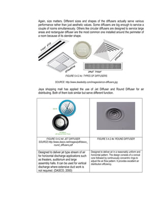
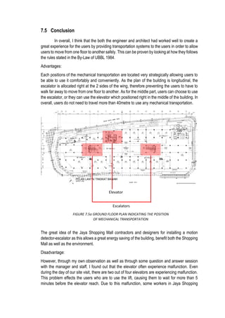
The document discusses the analysis of building service systems at Jaya Shopping Mall in Petaling Jaya, focusing on mechanical ventilation, air conditioning, fire protection, and transportation systems. It includes detailed sections on each system's components, functions, advantages, disadvantages, and compliance with regulations, along with case studies exemplifying their use. The project emphasizes learning through observation and comparison with relevant laws to understand service implications and enhance safety and comfort for occupants.


![6. AHUmag. (12, February 2015). AHU - Defination and Configuration Types. Retrieved from
www.ahumagazine.com: http://www.ahumagazine.com/air-handling-unit-definition-and-
configuration-types/
7. DASCO. (2000). Product Bulletin - Round & Jet Diffusers. Retrieved from dasco.net:
http://www.dasco.net/images/pdf/dasco_round_diffusers.pdf
8. Hoffman, P. (2006). Basic Refrigeration Cycle. Retrieved from Southwest Wisconsin
Technical College Website:
https://www.swtc.edu/ag_power/air_conditioning/lecture/basic_cycle.htm
9. Winterland, P. (2009, October). The Three Types of Air-Filters. Retrieved from
facilitiesnet.com: http://www.facilitiesnet.com/iaq/article/The-Three-Types-of-Air-Filters-
Facility-Management-IAQ-Feature--11235
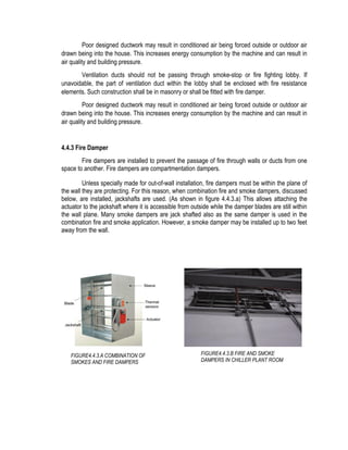
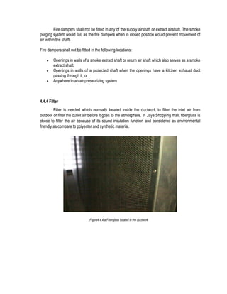
FIRE PROTECTION SYSTEM
10. Haack , A.H. . (2014, 8th December). Tunnel Safety and Security.[Weblog]. Retrieved 16
November 2015, from
http://www.sp.se/sv/units/fire/Documents/Skydd/ISTSS2008/KN4%20Thu%200930%20Ha
ack%20ISTSS_2008.pdf
11. Peacock , R.D.P. & Bukowski , W.B. (1990 ). A Prototype Methodology for Fire Hazard
Analysis . United States : US National Institute of Standards and Technology .
a. In-text citation: (Peacock & Bukowski , 1990 )
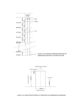
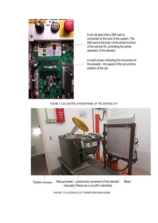
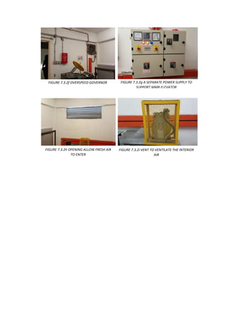
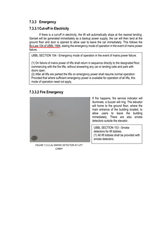
MECHANICAL TRANSPORTATION SYSTEM
12. Harris, T. (n.d.). Retrieved November 18, 2015, from
http://science.howstuffworks.com/transport/engines-equipment/elevator.htm
13. Schindler Home. (n.d.). Retrieved November 18, 2015, from
http://www.schindler.com/com/internet/en/home.html
14. Stein, B., & Reynolds, J. (1992). Mechanical and electrical equipment for buildings (8th
ed.). New York: J. Wiley & Sons
15. Strakosch, G. (2010). The vertical transportation handbook (4th ed.). Hoboken, N.J.: John
Wiley & Sons](https://image.slidesharecdn.com/finale-151212144317/85/Building-Service-Project-2-Case-Study-Report-163-320.jpg)