Downloaded 238 times

![7 | P a g e
2.1 Plants & Machinery
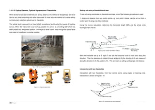
2.1.1 Construction regulations for Plants & Machinery
Under the construction regulations;
On all construction sites on which transport vehicles, earth-moving or materials-handling
machinery or locomotives are used, the project supervisor for the construction stage shall
ensure that: (a) safe and suitable access ways are provided for them; (b) traffic and pedestrian
routes are so organized and controlled including, where appropriate, by the provision of a traffic
and pedestrian management plan, as to secure their safe operation.
2.1.2 Earth moving & excavating equipment
Earth moving equipment, also known as heavy equipment, refers to heavy-duty vehicles,
specially designed for executing construction tasks, most frequently ones involving earthwork
operations. They are also known as heavy machines, heavy trucks, construction equipment,
engineering equipment, heavy vehicles, or heavy hydraulics. They usually comprise five
equipment systems: implement, traction, structure, power train, control and information.[1]
Heavy equipment functions through the mechanical advantage of a simple machine, the ratio
between input force applied and force exerted is multiplied. Some equipment uses hydraulic
drives as a primary source of motion.
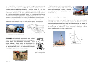
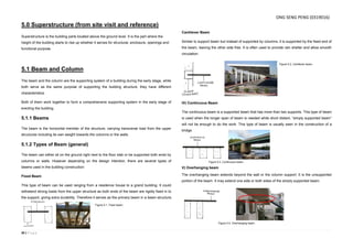
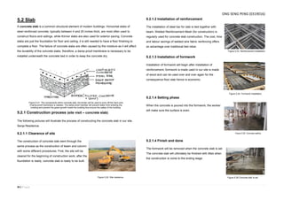
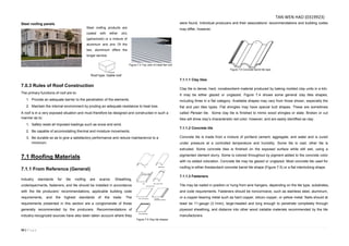
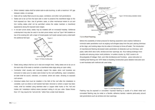
2.1.2.1 Examples of earth moving equipment
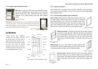
Loaders: Usually loaders are wheel loaders as wheels will
provide better mobility and speed and won’t damage paved
roads near as much as tracks. It has a wide square tilting
bucket on the end of movable arms to lift and move material
around. The bucket may be replaced with other tools like forks.
The function of loaders are loading materials into trucks, laying
pipe, clearing rubble, and also digging. Loaders aren’t the
most efficient machines for digging, as they can’t dig very
deep below the level of their wheels, like the backhoe can.
Bulldozer: Bulldozer is a tractor that is fitted with a dozer
blade, they are usually tracked for ground mobility through
rough terrain. Wide tracks help distribute the weight of the
dozer over large areas, preventing it from sinking into
sandy or muddy ground. The blade comes in 3 varieties: (a)
A straight blade that is short and has no lateral curve, no
side wings, and can be used only for fine grading; (b) A
universal blade, or U blade, which is tall and very curved,
and features large side wings to carry more material
around; (c) A combination blade that is shorter,offers less
curvature, and smaller side wings.
2.1.2.2 Types of earth moving equipment available on site
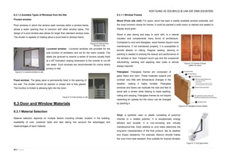
Backhoe loader: Backhoe loaders are common with small construction and excavation due to
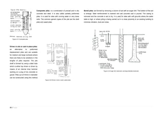
its small size and versatility. It consists of a tractor, front shovel and bucket and a small
backhoe in the rear end. Besides construction, backhoe loaders are also used for light
transportation of materials, powering building equipment, digging holes and excavating,
breaking asphalt, and even paving roads. The general purpose buckets can be switched either
to retractable bottom bucket, rock bucket or many more for different tasks.
Excavator: Excavators are heavy construction equipment consisting of a boom, stick, bucket
and cab on a rotating platform known as the "house". The house sits atop an undercarriage
with tracks and wheels. A cable-operated excavator uses winches and steel ropes to
accomplish the movements. They are a natural progression from the steam shovels and often
mistakenly called power shovels. All movement and functions of a hydraulic excavator are
accomplished through the use of hydraulic fluid with hydraulic cylinder and hydraulic motor.
Figure 2.10 Wheel loader
Figure 2.12 Backhoe loader 580
Super L on site
Figure 2.13 Section of Backhoe
Loader details
Figure 2.11 Wheel loader
MELISSA LIM LI LIN (0322680)](https://image.slidesharecdn.com/merged-151203061119-lva1-app6892/85/Building-Construction-Assignment-1-7-320.jpg)
![58 | P a g e
8.1 References
Books
Emmitt, S., & Gorse, C. (2005). Barry’s Introduction to Construction of Buildings (Vol.2). Wiley-
Blackwell.
Ching, F. D. K., & Adams, C. (1943). Building Construction Illustrated. (3rd
ed.) Canada: John
Wiley & Sons.Inc.
Chudley, R. (1987). Construction Technology Vol. 3. (2nd
ed.) Harlow: Addison Wesley
Longman Limited.
Chudley, R. & Greeno R. (2008) Building Construction Handbook. (7th
ed) Burlington:
Butterworth-Heinemann Elsevier.
Levy, S. (1992). The construction superintendent's handbook. New York: Van Nostrand
Reinhold.
Chudley, R., & Greeno, R. (2010). Building construction handbook (8th ed.). Amsterdam:
Butterworth-Heinemann.
Grey, A. (2011, July 8). Types of Roof Trusses. Retrieved October 18, 2015
Websites
Civil Engineering Home (n.d.) Retrieved 13 October 2015 from http://theconstructor.org/
How To Install A Window (n.d.) Retrieved 26 September 2015 from
http://www.thisoldhouse.com/toh/how-to/step/
Understand Building Construction. Foundations. (n.d.) Retrieved 14 October 2015 from
http://www.understandconstruction.com/introduction-to-foundations.html [Accessed 14th
October 2015]
Robertson, R. (2012, November 3). Roof Underlayment Installation & Detailing. Retrieved
October 18, 2015, from
http://inspectapedia.com/BestPractices/Best_Roofing_Underlayment.php
Home Building & Renovating. Foundations Explains. (n.d.) Retrieved 3 October 2015 from:
http://www.homebuilding.co.uk/2008/12/18/foundations-explained/
The Concrete Center. Foundations. (n.d.) Retrieved 7 October, 2015from:
http://www.concretecentre.com/technical_information/building_solutions/foundations.aspx
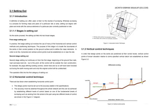
Setting Out (n.d.) Retrieved October 3, 2015 from http://bbstore.northbrook-
online.ac.uk/store/CITB/BW/materials/Sec05-Setting%20Out/Sec05-M02.pdf
Smith, J. (2013, July 15). How to Choose a Roof for Your Home | Today's Homeowner.
Retrieved October 18, 2015, from http://www.todayshomeowner.com/choosing-a-roof/
Grey, A. (2011, July 8). Types of Roof Trusses. Retrieved October 18, 2015, from
http://www.truswood.com/types of roof trusses.htm
Daniels, J. (n.d.). Guide To Design For RCC Columns. Retrieved October 16, 2015, from
http://www.civilprojectsonline.com/building-construction/guide-to-design-of-rcc-columns/
Interviews
Lim, T. (personal communication, 12 September 2015)
Shahabuddin, F . (personal communication, 14 September 2015)
Omar, A. (personal communication, 14 September 2015)
LIM JOE ONN (0318679)](https://image.slidesharecdn.com/merged-151203061119-lva1-app6892/85/Building-Construction-Assignment-1-58-320.jpg)

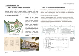
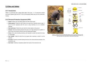
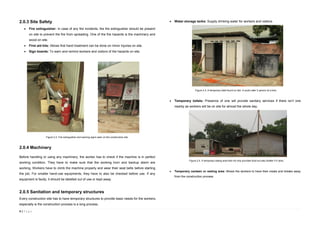
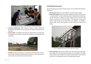
This document provides information about a construction site visit assignment by a group of students to two development projects in Selangor, Malaysia. The first project visited was the SENJA Residences, a 278 unit residential development located near Seri Kembangan. It will be completed in phases by 2017. The second project was a 650 square meter warehouse in Shah Alam for construction materials. The document then discusses site safety, personal protective equipment, machinery, transportation vehicles, material handling equipment, and the importance of safety attitudes on construction sites. Various photos of the sites and equipment are included. Safety protocols for working at heights, machinery operation, electricity, and fire prevention are covered.


