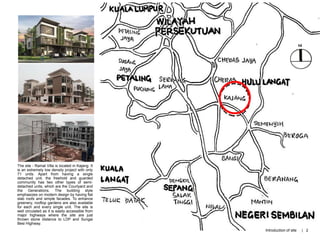
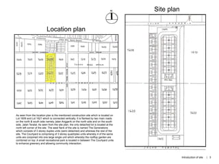
The site - Ramal Villa is located in Kajang. It
is an extremely low density project with only
71 units. Apart from having a single
detached unit, the freehold and guarded
community has two other types of semi-
detached units, which are the Courtyard and
the Generations. The building style
emphasizes on modern design by having flat
slab roofs and simple facades. To enhance
greenery, rooftop gardens are also available
for each and every single unit. The site is
well circulated as it is easily accessible from
major highways where the site are just
thrown stone distance to LDP and Sungai
Besi Highway.
Introduction of site | 2
Location plan
As seen from the location plan is the mentioned construction site which is located on
Lot 1609 and Lot 1621 which is connected vertically. It is flanked by two main roads
on the north & south side namely Jalan Anggerik on the north side and on the south
side, Jalan Teratal. As seen from the site plan, the only detached lot is located at the
north left corner of the site. The west flank of the site is named The Generations
which consists of 3 storey duplex units (semi detached) and whereas the rest of the
site, The Courtyard is comprising of 3 storey quadriplex units whereby 4 of the same
units are conjoined into one large single unit which whereby the rooftop garden are
combined on top. A small recreational park is located in between The Courtyard units
to enhance greenery and allowing community interaction.
Site plan
Introduction of site | 3
Construction is one of the most hazardous and dangerous industry that comprises of a wide range of activities involving construction, alteration and sometimes
also repair and maintenance. Hence, risks are intrinsic in any sort of construction. Accidents such as falling from heights, injures and fatalities are likely to happen.
Hence, site safety procedures should not be taken lightly and need to be reinforce onto any construction site. Employers in workplaces need to ensure the health
and safety in every aspects while working.
SITE SAFETY SIGNAGES
• Positioned at the main entry of the
construction to notify public regarding
the construction project.
• Signboards shows the name and type
of construction project, the
development firm, architect,
contractors, engineers and other
relevant members of the building team.
• To also act as to notify the pubic
regarding the members and people
responsible for the project.
• Positioned at main entrance of site to ensure
attention from anyone before entering the site.
• Positioned also in accidents prone area to
ensure the safety of workers.
• To act as a constant reminder regarding
restricted activities on site.
CONSTRUCTION
ORGANIZATION
BOARD
Safety precautions & equipment
Site safety
Site safety | 5
CONSTRUCTION ORGANIZATION BOARD INDICATION
BREAKDOWN
• Project title
• Project proposal & specifications
• Project location
• Development firm
• Architecture firm
• Structural Engineering firm
• Mechanical & Electrical Engineering firm
• Contractors & sub contractors
• Plan permit & approval reference
• Developer license number
• Advertisement & publicity permit number
• Project execution & termination date
FRONT ELEVATION
DRAWING OF
BOARD
SIDE ELEVATION
DRAWING OF
BOARD Site safety | 6
PERSONAL PROTECTIVE EQUIPMENTS (PPE)
Personal protective equipment (PPE) is anything used or worn by a person or a construction labour to minimise the risk to the person's health or safety. These
equipment are essential in order to allow construction labour to carry out construction works smoothly and safely throughout the entire construction project.
• Form of protective eyewear, usually plastic and
transparent.
• Designed to enclose or protect the area
surrounding the eye in order to prevent
particulates, water or chemicals from striking
the eyes.
SAFETY HELMET
• A hard top helmet which serves to protect the
head from injuries from hard falling objects.
• It is also to protect the head from major injuries
such as concussion upon falling down from a
higher level.
SAFETY GOGGLES
EAR MUFFS
• To act as protective gear to cover ears from
construction noise pollution which can hurt the
ears.
• Serves to also enclose the ears without
disrupting head comfort of construction workers
and at the same time shield them from loud
construction noises.
PROTECTIVE SUIT
• Usually a thick rubber like synthetic material
which covers the entire body from neck to calf.
• The suit is designed as to insulate the body
from any means of electrical conductivity and
the thickness is to protect the body from
external injuries.
SAFETY GLOVES
• Protective gear for the hand which is designed
using electrical insulated material such as
rubber.
• To protect hand from grazes and cuts during
construction and also to insulate the hand from
electrical conductivity.
SAFETY BOOTS
• To act as a protective gear for the foot. High top
design prevents the leg from getting cuts.
• Rubber and synthetic material in order to
prevent electrical shock and also to provide
walking comfort during construction.
Site safety | 7
CONSTRUCTION SCAFFOLDINGS
Scaffoldings are also considered as one of the major site safety equipment. Apart from acting as temporary support for the formworks of the buildings, it
also ensures the safety of the construction workers while allowing them to access the buildings different floors while the building is still under
construction and also to hasten the mobility and transportation of materials between floors of buildings and hence ensure the convenience and safety of
the construction workers.
SCAFFOLDINGS SETS
SCAFFOLDINGS SET UP
• Upon being set up, it serves to allow
accessibility, mobility and also ensure
convenience of workers
• Ensure convenience in transportation of
materials vertically from bottom to top.
Site safety | 8
HEALTH & HYGIENE
Heath and hygiene on site are one of the prime points that needs to be taken very seriously as it ensures the health of the work labour which are
essential to ensure the smooth construction process and productivity.
SANITATION
A typical toilet on site
Sanitary convenience should be taken into consideration as to ease the
workers and also to ensure the cleanliness and hygiene of the surrounding of
the construction site.
Rows of self constructed concrete
toilets on site
• Sanitary facilities and conveniences should be segregated according to gender
of users for the construction workers.
• Water are also provided for in order to maintain the cleanliness and hygiene of
the sanitary facilities on site.
• Ventilation and sufficient lightings are also needed to be present in these
facilities in order to ease convenience in these facilities.
TEMPORARY CANTEEN
Canteens are also important and essential in any construction site as it
provides food and beverages in order to maintain workforce and
productivity among construction workers and hence indirectly maintaining
efficiency and productivity within the construction site and project.
• Condition of the temporary canteen needs to be well hygiene as it
affects the cleanliness of food and beverages being consumed by the
construction workers.
• The temporary canteen needs to also be well lit, well ventilated and
shaded as to provide comfort for the construction workers when they
are having their meals.
• To ensure cleanliness, the canteen needs to be located further away
from construction dumpster and waste and also sanitary facilities.
• The location of the temporary canteen needs to also be strategic
around the site as to ease the convenience of the construction workers
to have their meal after work.
Temporary canteen constructed out of plywood timber.
Site safety | 9
GARBAGE COLLECTION
Garbage collection facilities are one of the most important facilities to be present around the construction as to ensure the cleanliness and the
hygiene of the surrounding of the construction site. The garbage facilities serve to act as a dedicated space for the disposal of sanitary wastes,
construction wastes and also domestic wastes around the site such as food and beverages wastes after consumption.
Main dumping site around the
construction site without any
sort of proper dumpster
Food and beverage wastes
are being littered around the
construction site disregarding
the site cleanliness.
Temporary facilities are not well
taken care off and gradually
becomes dumping spot for certain
construction waste
Construction wastes such as
spoilt and unusable zinc sheets
are dumped randomly around
the site.
The construction site has many
random dumping spots which
cleanliness are not emphasized.
Site safety | 10
Bad practices are common in local construction sites due to the lack of surveillances from higher authorities and also lack of emphasis on the penalties on certain
wrongdoings. Most of the bad practices are concerning site safety and also the health and cleanliness on construction site.
BAD PRACTICES AROUND CONSTRUCTION SITE
HEALTH &
HYGIENE
SITE
SAFETY
Construction workers are not well
equipped with safety glove while
handling and bending the
reinforcement bars. This practice is
dangerous to the workers as it will
injure the hands of the workers
while working.
Scaffoldings are not well equipped
with construction safety nettings.
This will increase the tendency of
the construction to fall from height
and also materials from falling
below.
Main dumping site is not
properly managed and
increase the chances of pests
breeding.
The canteen is situated at a
close distance from the main
dumping area which is
unhealthy and unhygienic for
the workers in terms of food
consumption.
The sanitary facilities are
not provided with efficient
water supply for cleaning
and it is not well lit and
ventilated. This is
unhygienic as it will attract
pests such as flies and in
the long run producing
unpleasant stench.
Site safety | 11
Site plants and machineries are mandatory in order to smoothen the construction process and also to hasten the phase and process of the construction in
order to meet the date of completion of the construction project, maintain consistency and accuracy and also to ensure the safety and health of the workers as
to avoid works from being done manually. Site plants and machineries varies from different construction projects which is also dependent on the scale of the
construction project. There are a vast range of construction plants and machineries that are used and a few of the examples are earthmoving and excavating,
lifting and vertical transportation and others.
LIST OF PLANTS & MACHINERIES USED ON SITE
ITEM DESCRIPTION MODEL & SPECS QUANTITY
1 Lorry Daihatsu 1 ton
Daihatsu 3 ton
1 No.
1 No.
2 Crane Mobile crane – Zoom Lion 25 tons
Mobile crane Kato NK 300 III
1 No.
1 No.
3 Excavator Mitsubishi 200
Hitachi 300
1 No.
1 No.
4 Concrete mixer 10 Nos.
5 Vibrator poker 10 Nos.
6 Compactor complete with engine 1 No.
7 Vibrator engine complete with pump 1 No.
8 Bar bender & bar cutter 5 Sets
9 Scaffolding & accessories 10,000 Set
10 High pressure jet pump 2 Sets
11 Generator set 2 Sets
12 Wielding set 1 Set
Plants & machineries
Plants & machinery | 13
EXCAVATION & EARTH MOVING MACHINERIES
These equipment and transportation are essential in order to smoothen and hasten the process of excavation and earthwork during the construction period on site.
Mainly, these excavators and transport used are to excavate the earth around the site and also to transport the soil and earth around at a large amount at a time. These
earth, soil and sand are also being transported by these means of transportations in order to level up the irregular site level of the construction site.
EXCAVATORS
Earth and soil from slopes and terrain are being excavated to create trenches and to even out land by these machineries.
EXCAVATOR BACKHOE LOADER
• Serves dig trenches for foundation and also
site clearing works.
• Used on site for site clearing and excavation works but usage are not as
heavy duty as compared to the excavator.
• The backhoe bucket can be substituted with various types of construction
attachments which can carry out various functions.
Plants & machinery | 14
Truck on site transporting the excavated earth to
designated location.
Truck releasing transported excavated earth onto
designated location on site for site levelling.
EARTH MOVING TRANSPORTATION & HAULING EQUIPMENTS
After the excess earth and soil from slopes and terrain are being excavated, these excess soil are being transported away to different designation around the
site either to be reuse as to even out the land or to be dump as construction waste.
• Trucks are hauling units which are used to transport excavated materials and construction wastes to
designated sites over a distance at a relatively low cost.
• Trucks being loaded with construction wastes and bulk materials such as rocks and earth by loaders.
• These hauling machineries increase efficiency of the construction process entirely and hence smoothen
the excavation and also the construction transportation process.
Construction trucks
Plants & machinery | 15
PAVING MACHINERIES
These equipment and lightweight machineries
are used alongside with roadworks
machineries and equipment.
VIBRATOR COMPACTOR
• Applied on site to compact the foundation of
the soil using the vibration force produced by
the engine.
• Serves to reduce the sizes and particulates
to a denser and more compact mass.
• Enhances stability of foundation of
earthwork before the paving works
commence.
CONCRETE PLANTS & MACHINERIES
Concrete machineries are widely used in any construction as it saves costs as
compared to prefabricating and transporting it from the factory. It also eases
construction workers’ convenience as it is mobile and easy to work with
CONCRETE MIXING TRUCK
• Serves to transport and also mixing the concrete
to the construction site.
• This piece of machinery serves to maintain the
concrete in liquid state through agitation by the
turning the drum in order to prevent it from
solidifying before reaching the construction site.
PORTABLE CONCRETE MIXER
• Serves to combine the cement,
aggregate and water to form
concrete homogenously and
producing it directly on site.
CONCRETE DUMP
• A dumping spot for unusable
concrete and slump tested
concrete to be disposed.
HIGH PRESSURE JET PUMP
• Portable machine which serves to
spray mixed concrete onto
designated spot on site evenly
and efficiently.
Plants & machinery | 16
OTHER SITE PLANTS, MACHINERIES &
EQUIPMENTS
PORTABLE ELECTRIC GENERATOR
• Serves to generate electrical supply when
there are no power supply available on
site.
• Ease convenience of workers as to utilize
it to obtain mobile electricity to operate
other machineries..
CONSTRUCTION LEVELLING
TELESCOPE (DUMPY LEVEL)
• An optical instrument used to establish or to
check the points in the same horizontal
plane.
• Serves to survey and build with a vertical
staff to measure height differences and to
transfer, measure and set heights.
BAR BENDER & CUTTER
• Used by construction workers to bend the
steel bar in various curvature for various
specific purposes.
• The excess bended bars can be then cut of
by the cutter which is also attached onto the
machine itself.
MOBILE CRANE
• Suitable for small scale construction by
which requires crane utilization without
having the need to install a permanent
tower crane .
• Easily transported to site having with little or
without setup and assembly of parts.
Plants & machinery | 17
External works are mainly the preliminary preparation that has to be carried out in order for the actual construction works to be done smoothly. This is to
ensure the smooth process of the construction works and to provide the construction and completion of site clearance and earthwork around the designated
site boundary. External work types consist of site clearing, site levelling and excavation, designating temporary facilities and also utility connections.
SITE CLEARING WORKS
Site clearing works are mandatory and serve as the fundamental basis in preparing the site for construction. It is the process of clearing any site construction
obstruction which could be any sort of existing natural vegetation or structures by which the presence are inappropriate for the commencements of site
construction. Site clearance works mostly include the removal of vegetation such as natural trees and stumps that are within the site boundary.
Two cuts for the undercut forming a pie shaped
cut line in the base of the tree trunk facing the
direction of which the tree is intended to fall. An
backcut which is 3-5cm above the base of the
undercut is cut at right angles to the falling
direction.
In order to remove the remaining tree stump the
dozer blade is placed against the stump and a
lifting action is furthered applied onto the stump.
The tractor is backed and the dozer
blade is lowered.
The stump is tilted forward until the
roots in front of the dozer blade are
slightly lifted out from the ground.
The dozer blade is now inserted
under the lifted roots.
While lifting the blade, a pushing
force is applied in order to break the
stump out of the ground and hence
entirely removing the tree from the
ground.
If the tree trunk still resists falling, a wedge is
hammered into the backcut to the direction
intended for the tree to fall.
External works
Step 1 Step 2 Step 3
Step 4 Step 5 Step 6 Step 7
External works | 19
EARTHWORK & EXCAVATION
After the procedure of site clearance works are done, earthworks are to be proceeded. Earthworks are engineering works involving the excavation and
land filling process through the constant moving, excavating, replacing, refilling and backfills bulk materials such as earth and soil on site. Besides,
excavation works are also to prepare the construction site for even and well levelled land for the smooth process of construction works to take place.
The topography and the elevation of the
terrain are studied and surveyed thoroughly.
The contour lines signifies the changes of
land in elevational views.
The cut line is then made to estimate the
amount of land to be cut and to be backfilled
with the amount of cut land.
The cut line is the marked to the intended
level onto the existing slopping land and
whereby holes are filled under the cut liens.
The marked cut lines will be removed and to
be used as filler to achieve the accurate and
efficient desired landscape..
The slopping topography to be cut or
excavated and the remaining bulk material
are used to backfill the designated the
spaced needed to be filled.
After ground has been cut out from its
original ground level, a battered surface will
form and the original ground level is reduced
to form a flat surface.
The designate zone that needs to be filled
are then filled up to the intended level, thus
producing a higher formation level as
compared to the original ground level, hence
forming a flat surface as well.
CUTTING & FILLING UP CLOSE
External works | 20
Site securing is important and essential as to avoid theft around the construction site and also to ensure each and everyone safety surrounding the
construction site, construction workers or public citizens alike. Apart from that designations are also an important point that should not be taken for granted
as the location of facilities are important to ensure the convenience of the construction worker and indirectly affect the progress and efficiency of the
construction project.
1. Toilets & Lavatories
2. Site offices & meeting room
3. Materiality storages
4. Staff & visitor carpark
5. Vehicle and machinery wash
6. Temporary water supply tank
7. Bar bending station
8. Cement storages
9. Canteen
10.Scaffolding and timber formwork
storages
11.Workmen hut
12.Dumpsite
Construction organizational
sign board and safety
signboard.
CONSTRUCTIO
N SITE
LAYOUT
LEGEND
Hoarding entry and fencing
surrounding the site to ensure
safety.
Coarse aggregate storage
Fine aggregate storage
Portable concrete mixer
Electrical Substation
SITE SECURING & DESIGNATIONS
External works | 21
SITE SETTING OUT
Site setting out is also considered as one of the major, essential and important preliminary works that needs to be carried out in order to allow the
commencement of construction works. Setting out is basically the establishment of the marks and lines to define the site boundary, the definite position and
also the level of the construction elements for the construction works to be proceeded with efficient and accurate reference to them.
• The temporary bench mark or the site datum post (1) is being set up as the
main reference point of the rest of the set up points.
• The base line is then being set up with reference to the datum post and on
the other hand acting as the reference line itself to all other setting out lines
and points by which all can be related.
• Corners posts are then set up in order to mark the main building boundary.
ON SITE DETACHED LOT SETTING OUT
PLAN
ON SITE DETACHED LOT
FOUNDATION TRENCHES
SETTING OUT PLAN• After the site setting has been carried out accurately. Profile
boards are being set up along all corners of the building.
• This step is to ensure the accuracy of the width of the walls
later on and also the width of the foundation trenches that is to
be excavated before the commencement of foundation works.
External works | 22
ON SITE DETACHED LOT SETTING
OUT PLAN DETAILS CLOSE UP
ON SITE DETACHED LOT
FOUNDATION TRENCHES SETTING
OUT PLAN DETAILS CLOSE UP
1. TEMPORARY BENCHMARK
/ SITE DATUM POST
Detailed drawings below are to be viewed with reference to the setting
out plans previously.
Detailed drawings below are to be viewed with reference to the
setting out plans previously.
2. CORNER POSTS
3. BUILDERS’ SQUARE
Act as a standard measurement tool
in order to measure and indicate an
accurate perpendicular angle (90
degrees) upon setting out at corner
posts.
1. TYPICAL PROFILE BOARD
2. FOUNDATION TRENCHES
External works | 23
FOUNDATION TRENCHES EXCAVATION WORKS
The excavation works for foundation and trenches are mainly to establish the size, shape and direction of the entire building frame. Besides, these
foundation trenches are also essential as it also serves to ex=stablish the width and position of the walls using the profile boards that has been set up
as guidelines and reference points.
A temporary site datum post is being
set up at a strategic spot as to act as
reference point.
A tripod holding the construction levelling telescope (dumpy level) is used to obtain perpendicular
angles with the help of the plumb rod being attached onto the corner post or with the help of a site
datum.
OR
The well levelled telescope will be
then used to act as surveillance in
order to make sure the profile boards
are well levelled.
Step 1 Step 2
Step 3
Step 4 Step 5
External works | 24
TEMPORARY FACILITIES & SERVICES
These basic facilities ad services are mandatory to be present before the actual construction works proceed. The contractor are assigned the responsibility to
consider thoroughly the types of all temporary facilities and services required in order to smoothen the construction process. Services such as personal
sanitation and food and beverages are also the basic requirements which are to be present in the construction site. These facilities and services can range
from infrastructures to basic work facilities and services.
HOARDINGS
These hoardings which surrounds the site boundary
serve to secure the sit perimeter and to prevent noise
and also dust and construction waste to obstruct
adjoining properties
CROSS SECTION OF A TYPICAL HOARDING
CONSTRUCTION
ORGANIZATIONAL SIGN
BOARD
Displays and notify the public
regarding the information of the
construction project and also to notify
the public regarding the presence of
the construction site at that particular
area.
SITE OFFICE & MEETING ROOM
To hold meetings directly on site between the building
team in order to save time and solve construction issues.
VEHICLE & MACHINERY WASH
To ensure the hygiene and cleanliness of the transport
and vehicle before exiting the construction site to a public
and non construction area.
External works | 25
BAR BENDING & CUTTING STATION
Serves as a workplace dedicated for
construction workers to bend and cut
reinforcement bars for particular construction
purposes.
SCAFFOLDINGS
Serves as a temporary structure to support the
formwork of the construction and also to ease
the construction workers vertical mobility around
the building during construction works.
MATERIALITY STORAGES
A dedicated place to store construction
materials such as cement, aggregate and also
building accessories in order to protect the
materials and accessories from damage due to
weather.
TEMPORARY CANTEEN
A space designated for the construction workers
to have their meal while taking a break from
construction works.
WORKMEN ACCOOMODATIONS
Space dedicated to house and accommodate
workers to stay and rest throughout the entire
construction project phase last.
External works | 26
SANITATION FACILITIES
To provide comfort and relief fro the
construction workers and at the same
time serves as a dedicated spot for
sanitation purposes which ensure on
site hygiene and construction workers
health.
ELECTRICAL SUPPLY
To provide constant flow of electricity in order for the
operation of machineries to be carried out smooth
and constantly without jeopardizing the work
efficiency and productivity.
PORTABLE ELECTICAL SUPPLY
To accommodate for far range usage of
electric supply as to enhance
convenience for the workers to operate
the machineries during power outage or to
work at a further range of reachability
within the construction site..
External works | 27
SLUMP TEST
Slump test are also one of the major point that should not to be taken for granted as it is once of the most significant task and procedure of
external works. Slump tests serves to examine the mixture and quality of a batch of premixed concrete and hence to determine its suitability of
usage for construction works .
BASIC SET UP FOR SLUMP TEST
COLLAPSED
SLUMP
SHEAR SLUMP
ZERO SLUMP TRUE SLUMP
Detailed drawings above indicating different types of slumps produced. Out of all, only the concrete batch being determined
as true slump is qualified and suitable to be proceed onwards to be used for construction works. The rest of the concrete
batches are either too liquid or too solid in state which are unsuitable for construction.
Construction worker carrying out
slump test and measuring the
height of the slump in order to
determine the suitability of the
batch of concrete.
External works | 28
SLUMP TEST PROCEDURE
The slump cone is dampen and is
filled with 1/3 full by volume and rod
25 times with a tamping rod.
The cone is further filled with 2/3 by
volume. This layer is rod 25 times
penetrating through by not all the
way through the bottom layer. The
rodding action is distributed evenly
over the entire cross section of the
layer.
The cone is later then filled till it
overflows. This layer is again rod 25
times with rod penetrating into but not
directly through the second layer. The
rodding is again distributed evenly
across this entire cross section of the
layer.
The excess concrete from the top of
the cone is then removed using the
tamping rod as a screed. The
overflow base of the cone is also
cleaned.
The cone is then lifted vertically
immediately with slow, even motion.
The cone must be ensured to not be
tilted in anyways throughout this
process. The withdrawn cone is then
inverted and place next to the
slumped concrete without touching it.
A straight edge is laid across the top of the cone.
The amount of slump in inches is then measured
from the bottom of the straight edge to the top of
the slumped concrete at a point over the original
center of the base. The examination should be
completed at an elapsed time of mot more than 2
½ minutes. The concrete is then discarded and
shall not be used to perform any other tests.
External works | 29
Step 1 Step 2 Step 3
Step 4 Step 5 Step 6
CONCRETE:
The quality of concrete is
good and fast, with the
characteristic cube
strength and addition
water to cement with a
ratio of 0.45 to provide
optimal compressive
strength
STEEL:
Wieldable steel for
reinforcing concrete,
coiled to provide tensile
strength
Shallow piled foundation is used for the particular site. Piling is a more suitable foundation for this structure rather than the rafting foundation because the
structure is a three storey semi detach house with a soil condition that is not hard and also very stable. Also, it is able to withstand the load capacity of the
semi-detached house. Raft foundations are more potentially used for unstable type of soil or soils that are highly compressible .
Foundation of a structure is always constructed below the ground level so as to increase the lateral stability of the structure. It includes the
portion of the structure below the ground level and is built, so as to provide a firm and level surface for transmitting the load of the structure
on a large area of the soil lying underneath. The solid ground on which the foundation rests is called the Foundation Bed.
REINFORCED CONCRETE PILE
PILING
FOOTING
( SITE )
RAFT FOOTING
( REFERENCE )
MATERIALITY:
foundation
TYPES OF FOUNDATION
Foundation | 31
MACHINERY ANALYSIS
HYDRAULIC PILING MACHINE
Back stay : transfer the counterweight tension from the leader
towards the ground to stabilize the drive
Crane : lift and hoist the pile
Diesel pile hammer : create the magnitude of force to drive the
pile by inducing downwards momentum in the metal ram.
Leader : provide vertical attachment to support for the pile
hammer
Helmet : to distribute the force from the hammer to the pile evenly
and prevent damage
1: noise pollution, affecting human and
animals sleeping quality and patterns,
sensitive devices and induce sensory-
related illness
2. Pose structural damages such as
settlements to nearby natural or
man-made structure due to
propagation of intense vibration
Top Sheave
Leader
Diesel Pile Hammer
Crane
Helmet
Back Stay
Pile
HYDRAULIC PILING
HAMMER SECTION : ( 4 )
Foundation | 32
PILE CAP SPECIFICATIONS
ONE PILE CAP TWO PILE CAPS
THREE PILE CAPS FOUR PILE CAPS
PILING LAYOUT
IN A SINGLE
UNIT
A pile cap is a thick concrete mat that rests on concrete or timber piles that have been
driven into soft or unstable ground to provide a suitable stable foundation. It usually forms
part of the foundation of a building, typically a multi-story building, structure or support base
for heavy equipment. The cast concrete pile cap distributes the load of the building into the
piles. A similar structure to a pile cap is a "raft", which is a concrete foundation floor resting
directly onto soft soil which may be liable to subsidence.
Piles
intersecting
two separate
points.
Pile
Pile cap
Reinforced concrete
Ground beam to
support the walls
Pile cap
Foundation | 33
Ends of the piling pipe The reinforce steel is placed
before filing up the concrete bar
foundation.
Hydraulic Pile machine
hammering down the pipe pile
PILING PROCESS
Form and layout
Timeframe
Investment
Underground Water
Condition
Construction method
Building Code
Requirements
Factors to avoid
during piling process
Exceeding Load
Excessive Moisture
Intense Vibration
Plumb Error
Considerations
before design piling
specification
Foundation | 34
GRADE BEAM
BEAMS
A beam is a horizontal structural element that is capable of withstanding transverse loads (floor slab/roof slab) primarily by resisting bending. They transfer all
the loads including its self weight to other structural elements below (columns/walls). In other words, a column is a compression member.
The grade beam used at the site was of reinforced concrete, and it was positioned horizontally at ground level to support the superstructure, transferring the
load to the piles below.
Pile caps are interconnected with grade beams
and ground slab to ensure lateral forces can be
distributed to all the piles.
The piles and grade beams of the building at our site work in conjunction to elevate the
structure, provide vertical and lateral support for the elevated home, and transfer loads
imposed on the elevated home and foundation to the ground below.
Beams & columns | 36
GRADE BEAM
Construction Process
Reinforcement and Formwork
Footings and grade beams must be reinforced to resist the
moment forces that develop at the base of the piers due to the
lateral loads on the foundation and the elevated home
After the piers have been drilled and poured, trenches are dug for the grade beams. Wood is used to create
formwork and steel reinforcing is placed inside the formwork. The reinforcing from the pier is tied to the reinforcing
in the grade beam.
Grade beams must be a minimum of 200mm by 600mm with 2 – 15M bars top and bottom.
An acceptable void form must be
placed under all grade beams.
Beams & columns | 37
Both ends of the beam are rigidly fixed into the supports. Main
reinforcement bars and stirrups are provided.
Fixed Beam
Reinforcement
Steel bars are added within the concrete beams to
provide extra strength and support to the beam itself.
Above is the reinforcement configuration of the concrete beam to
handle tension and sheer load.
CROSS SECTION
OF REBAR
Beams & columns | 38
Beam
formwork
• Beam soffit must be thickened timber or strengthened plywood.
• Beam sides 18mm plywood or 25mm boards, with studs (cleats) at 500 to 600mm
centres. Deep beams (over 600mm) should have walkers and ties.
• Use angle fillets in the beam side to soffit joint where possible.
Beams & columns | 39
Beam
Construction process
Step 1
Erect the props and support, set up
the soffit of the beam.
Step 2
Construct formwork for the side of
the beam.
Step 3
Place the steel reinforcement.
Step 4
Erect the other side of the beam
formwork, and complete with struts for
extra support.
Step 5
Pour the concrete into the
formwork.
Struts
Concrete filling
Beams & columns | 40
Ground floor
First floor
Second floor
COLUMNS
A column is a vertical structural element that transmits, through compression, the weight of the structure above (the ceiling/roof slab) to
other structural elements below (foundation). In other words, a column is a compression member.
Reinforced concrete columns
Sizes of the columns
The sizes of the
concrete columns on
site differ from one
floor to another. The
bottom most floor has
a more thorough
reinforcement, and is
larger in size due to
the amount of load
and weight that it will
have to withstand.
For design purposes, the columns are separated into
two categories: short columns and slender columns.
These columns are prone to face different kinds of
failures.
Failures of columns due to sizes
Beams & columns | 41
Column
Formwork
Concrete formwork is the temporary structure built to support and confine concrete until it hardens. Formwork refers to vertical forms used to form walls and column.
It consists of the following:
Side & End Planks, Yoke, Nut
& Bolts. The two end & two
side planks are joined by the
yokes and bolts.
Adjustable steel
clamps
Plan and elevation of
column formwork
The four panels are joint by clamps that
help tighten them to build the formwork.
Beams & columns | 42
Columns
Reinforcements
Concrete is strong when compressed, but they need to be somewhat elastic to regain
their height after being compressed by live loads (people), and if they’re turned to
twisted by dynamic loads (wind/earthquake). Concrete columns must always have
steel reinforcement because they are subject to bending.
The columns on site are composed of concrete with an embedded steel frame to
provide reinforcement.
formwork
Bracing
Column bracing maintains the accuracy of the column form
position and plumb so that it is within tolerance. It is able to
withstand results of forces acting on either the column formwork or
the bracing.
On site: Bracing is applied to support the formwork of columns
Beams & columns | 43
COLUMN
Construction process
Step 1
Place the reinforcement on the
ground, and pour the concrete
Step 2
Set up the panels around the
steel bars and bind them together
with steel clamps
Step 3
Brace the formwork
Step 4
Pour the concrete into the
formwork.
Beams & columns | 44
When constructing the floor system it is important to take the type of flooring, the laying of pipes
and reinforcement into consideration. The type of flooring in a house must be adequately
supported by the flooring structure below. Floor systems are the horizontal surface of a room or
interior space and its supporting construction. Floor systems must support both live loads and
dead loads which then transfer to the supporting beams, columns or loadbearing walls.
Concrete slab are common foundation or floor systems in many parts of the world. Particular in
warmer climates with soils that are stable. Concrete slabs are plate structures that are
reinforced to span either one or both directions of a structural bay.
A building concrete slab consists of (from ground up) 4” of sand, gravel, or crushed stone; a
layer of 6 mil polyethylene used as a vapor barrier . A layer of wire mesh embedded in the
concrete.
One way slab is supported on two opposite side only thus structural action is only at one direction. Total load is carried in the direction perpendicular to
the supporting beam. If a slab is supported on all the four sides but the ratio of longer span 1 to shorten span is greater than 2, then the slab will be
considered as one way slab. Main reinforcement is provided in only one direction for one way slabs. One way slabs are designed for flexure and shear on
a per meter width basis, assuming that they act as a series of independent strips. Thus one-way shear in slabs is often referred to as beam shear, and
design for flexure and shear is carried out using a beam analogy.
Ground floor slab is built on a compacted hard ground
supported by beams.
One way slab and beam
slab
ONE WAY SLAB
slab | 46
SLABS SUPPORTING BY BEAMS
One way slab supported on beams on all four sides
One way slab supported on beams on two sides
 Provides useful flat surface
 One way slab may be used when there is architectural
limitations
 It is the simplest form of slab design
 Main reinforcement placing is one way, so there is a little
congestion than two way slab.
When a slab is supported only on two parallel apposite
edges, it spans only in the direction perpendicular to two
supporting edges. Such a slab is called one way slab. Also,
if the slab is supported on all four edges and the ratio of
longer span(ly) to shorter span (lx) i.e ly/lx > 2, practically
the slab spans across the shorter span. Such a slabs are
also designed as one way slabs. In this case, the main
reinforcement is provided along the spanning direction to
resist one way bending.
APPLICATIONS OF ONE WAY SLABS
BEHAVIOR OF ONE WAY SLAB
slab | 47
The slab above ground floor is known as intermediate slab. It usually takes 7-14 days for concrete slab to cure. But for intermediate
reinforced concrete slab it requires formwork for temporary support while the
concrete is wet, which delays the construction process for approximately 7
days. The intermediate floor includes an intermediate floor layer including an
elastic and resilient material. Intermediate floor slab is usually cast between
100-300mm, depending on the live and dead loads asserted on the slab.
Slab formwork and shoring
Fresh concrete must be shaped and supported by formwork until it
cures and able to support itself. Moreover, temporary supports
called shoring are used to support beam and slab forms.
INTERMEDIATE SLAB
slab | 48
Step 3
Concrete class is cast on top of the wire reinforcement
with the formwork acting as a mould. The concrete is then
spread by until the form is full and even. The ground
taxes 1-2 days to cure and after curing of 14 days, the
formwork are then removed.
Step 1
The desired area for ground of a site is excavated and
compacted, the hole is usually larger than the slab for
formwork to fit in the hole.
Step 4
Scaffolding and shoring are placed on the ground floor to
support the timber centering of the first floor. The
formwork of the first floor is installed on the timber
centering.
Step 5
Concrete is then casted into the formwork that holds the
welded wire reinforcement in place. Finally, a layer of
concrete is casted on top of the reinforcement and an
intermediate slab is formed.
Step 2
Formwork is installed around the compacted hardcore.
Welded wire reinforcement is layered on top of the damp
proof membrane.
CONCRETE GROUND AND INTERMEDIATE FLOOR SLAB
Construction process
slab | 49
SLAB
DETAILS
• Formwork for slabs and beams consists of sole plates,
wedges, props, head tree, planks, batten and ledgers.
• Beam formwork rests on head tree.
• Slab form work rests on battens and joints
• If prop height are more than 8’ provide horizontal braces.
A beam-and-slab system, with a one way slab, and beams cast
compositely with the slab, is a highly efficient floor system.
Ground floor depth usually varies from 100-300mm, depending on
the ground bearing capacity and also the live ad dead load.
Formwork for concrete beams and slabs
slab | 50
TYPES OF WALL
A wall in general, is rows of bricks stacked vertically to a certain height. Walls are important element in a building as it not only bears the load of
the home; it also serves as a divider between spaces. They are also sound barriers and fire walls that protect the interior space of a building.
Bears load resting upon it by conducting its weight to a foundation
structure. The materials most often used to construct load-bearing
walls in large buildings are concrete, block, or brick.
Does not support any gravity loads from the building hence doesn’t
bear any weight besides its own.
1. Roof spans between external walls and internal load bearing wall.
2. Floor spans from external wall to internal load bearing wall.
3. Load bearing wall transmits part of roof load to foundation.
4. Load bearing wall transmits part of roof and floor load to foundation.
5. Roof spans from external wall to external wall..
6. Floor spans from external wall to external wall.
7. Non load bearing walls built off floor surfaces.
8. External load bearing walls transmit part of roof and floor load to
foundation.
Load
Load Bearing Wall
Non- Load Bearing Wall
Legend:
Wall system
Load bearing wall Non Load bearing wall
walls | 52
Step 5
Tap it into place until the top edge of the brick lines up exactly with the fishing
line guide..
Step 6
Scrape away any excess mortar that has been squeezed from between the
bricks as you go before it dries and hardens. Ensure that you remove the
mortar before it hardens.
Step 8
Once the corners are built, simply move the fishing line up, row by row, and fill
in the spaces between the corners. Because your bottom row is level and your
corners are vertical, your whole wall is sure to be level and vertical.
On-site:
Fishing lines are
extended at
corners to indicate
levels. During brick
layering process.
Step 7
Use a spirit level to check that the row is level and to ensure that the corners
are vertical (i.e. straight up and not leaning in or out).
BRICK-LAYERING
PROCESS
Step 1
Bricks must be laid on a concrete slab or foundation.
Step 3
Place enough mortar to lay 2-3 bricks at a time.
step 4
'Butter' each new brick by applying mortar onto the end of the brick
before placing it hard up against the preceding brick and into the mortar
bed. .
Step 2
Start by building the corners. To lay the first course of bricks, use
your trowel to spread mortar onto the concrete surface. Use a
fishing line stretched tight between the corners to lay the first row
of bricks. The back top edge of every brick laid must be exactly in
line with the fishing line.
walls | 53
TYPES OF BRICK
USED
Cement Sand Brick
Economical friendly
Uneven surface thus requires plastering
Offers excellent strength as a load-bearing member.
Common Burnt Clay Brick
Used in general work with no special attractive
appearances
Requires plastering and rendering
Thermal and acoustic insulation
Fire resistant
On-site:
Party walls (fire wall) are built using burnt clay brick due to
its fire resistant property. The rest of the walls are built
using cement sand bricks because it is more economical.
On-site:
Bricks at the top of the non bearing walls are arranged
diagonally to fill up the space at the top of the wall. This is
a bad exercise in construction as it weakens the wall
greatly.
On-site:
Walls are chased after built to run electrical wires and
power points. This is done before plastering process.
walls | 54
PLASTERING
PROCESS
Step 1
When plastering walls, try to avoid working in the direct sun or drying
winds. Plaster needs to retain its moisture for as long as possible.
Step 2
Load your hawk with plaster mix and scoop it onto the steel trowel.
Apply to the wall with pressure.
Step 5
Wet the leveled plaster with water (flicked lightly with a brush), then use
a float to smooth the surface.
On-site:
Metal brackets are installed to ensure straight edges when walls are
being plastered. Thickness of plasters are also marked to ensure
even plastering work.
Step 3
Plaster small areas at a time. A whole wall should be completed in one
operation.
Step 4
Once the plaster starts to stiffen, level the surface by pulling a straight
edge over the plaster with a sawing motion.
Step 6
Cover the plaster area with plastic or use a fine spray of water to keep it
damp for as long as possible (up to 7 days).
walls | 55
Stairs are the conventional means of vertical access between floors and different levels in buildings. Stairs are a series of steps, each elevated a
measured distance, leading from one level of a structure to another. It should be constructed to provide ready, easy, comfortable and safe access up
and down with steps that are easy to climb, within a compact area, so as not to take up excessive floor space.
TYPE OF STAIRS
2 parallel flights of straight stairs joined by a landing
that requires 180 degree turn in the walk line.
Half-turn staircases are also a variety of staircases
with straight flights. Just like quarter-turn stairs they
also have a landing, but here it changes a direction of
the flight by 180 degrees already and also serves as a
place for rest when moving. The landing divides the
staircase into two, thereby reducing quantity of treads
in one flight, and makes walking more comfortable.
Staircases of this type are very convenient, functional,
and safe.
COMBINATION OF
OPEN AND CLOSE
STAIRWAYThe staircase is sandwiched between a
wall and a open stairwell.
The double quarter turn or double quarter landing allows
the stair case to turn through 180 degrees. This is
achieved by turning 90 degrees on two large square
steps or landings.
staircase
HALF-TURN STAIRCASE DOUBLE-QUARTER TURN
STAIRCASE
staircase | 57
The staircase connects the 3 floors. The
construction of the staircase is easy as it is
continuous from the lowest level.
Stairwell is formed between the two parallel flight of stairs.
STAIRWELL
STAIRWELL
SECTION DRAWING OF STAIRS
staircase | 58
STAIRS
TERMINOLOGY
The headroom is sufficient for the user with a height clearance of 2.2m.
The rise is constant so that it is safe for the user. A width of
RISE, THREAD & HEADROOM
staircase | 59
FORMWORK & PROCESS
Formwork is the molding into which wet concrete is poured to give the user greater control over the exact shape of the finished, cured concrete.
Formwork can be built with almost anything but is most often built with a combination of timber, plywood, and steel or aluminum hardware. Formwork
can either be dismantled after the concrete has cured to an acceptable level, or it can be left to remain embedded on a permanent basis.
The basic concept of formwork is the creation of “walls” that will sand-which concrete poured between them.
Step 2
Bracing
Step 8
Pouring the Concrete
Step 4
Reinforcement added
Step 5
Installing Steps
Getting the Formwork Right
Step 3
Assembling Form
Pouring concrete into the
mold. Concrete is applied
from the top till the
bottom of the stairs.
Concrete poured is left
to dry and harden.
The framework is being
removed.
Step 1
staircase | 60
CONCRETE STAIR
CONSTRUCTION
Concrete stairs span between landings. Where there are loadbearing walls around the stair, it is generally economic to build. The landings into the
side walls as one-way spanning slabs and construct the flights as inclined slabs between the landings. Concrete staircases are especially popular as
it lasts longer relative to wooden staircases and is cheaper than installing staircases constructed from metallic materials. When designed correctly,
a concrete staircase is not only functional but can also add aesthetic value to the overall design of the building.
Picture shows how the staircase is built into the wall.
Inclined Slab Stair
staircase | 61
CIRCULATION
STANDARD REQUIREMENTS
Minimum requirements
Thread : 225 mm
Risers: 180 mm
( less than or 16 risers per flight )
Width of thread: 900 mm
( measured from outside the stringer )
Landings provide well-needed resting stages or a platform that allows
others to pass, enabling less mobile users to move at their own pace.
Two landings as resting platforms.
The width of the staircase is wide enough to
promote two way circulation.
40
Steepness of the stairs constructed is roughly 40 degrees.
The inclination is safe and comfortable for the users.
staircase | 62
CORE DRILLED AND
GROUTED
HANDRAIL
DETAILS900mm to 1m above the pitch line of the stair.
Start 300mm before the first step and end at the top step.
Grout is a particularly fluid form of concrete
which is used to fill gaps. Railing post is directly
drilled into the cement stairs.
Recommended installation method for all in-ground
rails and railing to be installed permanently into a
concrete slab.
Measure and mark
installation location of
railing posts.
Drill 3” diameter x 4”
deep core in concrete
for each post location.
Fully insert into hole and
make sure it is properly
aligned and level.
Fill the hole with grout.
The height of the railing is at 90cm which is safe for the users.
staircase | 63
WINDOWS
A window is an opening formed on a wall or roof primarily to admit daylight through some transparent or translucent material. Windows provides
controlled natural ventilation to buildings and make a major contribution to the visual appearance of buildings.
SLIDING WINDOWS
Open with the sash sliding left or
right. Sliding windows are easier
and faster. In a single slider, one
sash slides to open. In a double
sliders are create for providing air
circulation.
CASEMENT WINDOWS
Hinged at the side and open
outward like a door. It looks like a
picture window because unlike
double hung or sliding windows. A
casement window has no rail,
some casement windows are
simply pushed open but most have
a hand crank
AWNING WINDOWS
Hinged on top and open outward,
enabling ventilation without letting
in rain or falling leaves. Screens
are on the inside of the window,
where they are more protected
from the elements.
FIXED WINDOWS
Open with the sash sliding left or
right. Sliding windows are easier
and faster. In a single slider, one
sash slides to open. In a double
sliders are create for providing air
circulation.
B
A
C
D
WINDOWS anatomy
Doors & windows | 65
Frame
Sash
Glass
Jamb
Mullion
INSTALLATION METHOD OF ALUNIMIUM FRAMES
Step 1
Clean the opening. Ensure it is dry
and free from dirt, oil and debris.
Step 2
Apply water resistant coating to the
masonry. Extend the coating into
the opening on all four sides.
Step 3
Confirm the opening is plumb, level
and square. Measure and mark the
opening where the interior of the
new doors will be placed.
Step 4
Secure clips to the window frame.
Step 5
Done.
Doors & windows | 66
DOORS
A door is a solid barrier that is fixed to a frame in an opening in a wall to hinge, pivot or slide open (or to close). The door opening, doorway, allows
access and egress from building and between rooms, compartments and corridors. As a component part of a wall, the door and its frame are integral
to the overall performance of the wall.
POCKET DOOR
A pocket door is a sliding door that
disappears, when fully open, into a
compartment in the adjacent wall.
Pocket doors are used for architectural
effect, or when there is no room for the
swing of a hinged door
FLUSH DOOR
A flush door is a completely
smooth door, having plywood or MDF
fixed over a light timber frame, the
hollow parts of which are often filled
with a cardboard core material. Skins
can also be made out of hardboards.
SLIDING DOOR
A sliding glass door or patio door, is
a type of sliding doors in
architecture and construction. It is a
large glass window opening in a
structure that provides
access from indoors to the outdoors.
Helps in air ventilation and natural
lighting entering the building.
TIMBER DOOR
A door constructed with panels, usually
shaped to pattern and is installed
between the stiles and rails that form
the outside frame of the door. As a
main door for the building.
DOORS ANATOMY
Doors & windows | 67
INSTALLATION METHOD OF DOORS FRAME
Step 1
Verify and confirm the door location
and the dimensions of the rough
opening.
Step 2
Confirm the opening is plumb,
level and square.
Step 3
Measure the width and height
of the opening.
Step 4
Lintel placed on the top of the doors to
support the following bricks wall
construct.
Step 5
Pre-drill and fasten the treated.
Step 6
Done.
Doors & windows | 68
Roof is an assemblage to provide cover for homes, buildings, and commercial, industrial, and recreational areas. Roofs are constructed in different forms and shapes
with various materials. A properly designed and constructed roof protects the structure beneath it from exterior weather conditions, provides structural support for
superimposed loads, provides diaphragm strength to maintain the shape of the structure below, suppresses fire spread, and meets desired aesthetic criteria.Modern
roof construction usually consists of an outer roofing assembly that is attached atop a deck or sheathing surface, which in turn is supported by a primary framework
such as a series of beams, trusses, or arches.
Section of the top roof
Mono pitched roof
Flat roof concrete
Roof top plan
MONO PITCHED
ROOF
A single-sloping roof surface and
often not attached to another roof
surface. It is usually for storage.
Characteristics:
- Simple installation
- Low maintenance
- Low cost
- Drain away rainwater
FLAT ROOF
A roof which does not exceed 10° to
horizontal
Characteristics:
- Light weight
- Wind resistance
- Easy access for gutter system
- Space for placing equipment
- Easy to maintain
TYPES OF ROOF
roof
roof | 70
STRUCTURE
THE PURLIN ROOF
The purlin roof consists of both rafters and purlins. The ridge purlin is supported by posts. The rafters act as simple supported beams between the
purlins, either with or without cantilever. Purlins must be supported by load bearing walls or by structural beams and any horizontal thrust from the
purlin must be catered for. the strut and its associated connections and supports should be of adequate size and strength to resist buckling and to
carry the appropriate loading.
PURLIN
Any horizontal
structural members
FASCIA BOARD
Long, straight board that runs along the
lower edge of the roof. The fascia is
fixed directly to the roof trusses and
usually does all the work of supporting
the bottom row of tiles and carrying all
the guttering.
RAFTERS
Structural members (beam) that support
the roof deck and associates the load
L SHAPED
ANCHOR
BRACKET
Secure the rafters to
the roof beam
roof | 71
INSULATION
Thermal insulation in a building is very important to even the temperature of the
spaces within the buildings. The purpose of insulation is to provide resistance flow
of heat and reduce unwanted heat loss or gain.
Metal roofing
Double sided sisalation foil
Ventilation space
Metal roofing
Purlin
Double sided sisalation foil
Rafters
Ceiling lining
GUTTER SYSTEM
A gutter system is part of the roof. It consists of strainer, outlet, offset,
elbow, downspout and etc. The main purpose is to protect a building's
foundation by channelling water away from its base. The gutter also helps
to reduce erosion, prevents leaks in basements and crawlspaces,
protects painted or stained surfaces by reducing exposure to water and
provides a means to collect rainwater for later use.
Double sided sisalation foil
Metal roofing
Anchor bracket to roof beam
Gutter w/ domes roof outlet
Vistaboard
Brickwall with plaster on both sides
Gauge to fascia board
Stopened outlet
Running outlet
Downpipe
Offset bend
Pipe socket
Shoe
Gutter angle
The advantages of insulation
• Control the internal temperature of the building
• Prevents moisture being introduced into the ceiling by outside
weather conditions such as rain, humidity or precipitation
• Decrease the effects of damp which may lead to serious
illnesses and structure failure
• Fire retardant that improves fire safety
• Energy efficient as it reduces the amount of energy required to
cool a building and decrease electricity usage
roof | 72
CORRUGATED METAL ROOFING ( SITE )
Metal roof decking is corrugated to increase its stiffness. It is designed for pitched, flat, or arched construction on virtually all types
of buildings. Roof deck is popular because it is strong, lightweight, economical, and easy to install. Therefore, the smaller columns
are used to support the structure in residential houses.
CORRUGATED
METAL DECK
Advantages:
• Lightweight and reduce the load
• Reflects solar heat and can cut back
on cooling costs immensely
• High durability
• Low maintenance
Disadvantages:
• Noisy in the event of heavy rain
• Higher cost
Fastener arrangement
Reason using
screw as fastener:
• Faster to install
• Consistent screw installation
streamlines the inspection
process with no special
inspections
• Save time and money with
painted decks
• No need to repaint or touch up
from welding
• Reduce costs by eliminating the
need for welding leads, welding
rod, portable welders, fuel, and
certified welders
roof | 73
Gaps for
draining
water
Batten
TILES ROOF (
REFERENCE)Roof tiles can be an alternative for the metal roof of the selected site. It is also designed to drain away the rainwater as the overlapping of the tiles
prevent rainwater from dripping into it. Materials such as clay, fibre cement and concrete are used for the roof tiles.
Where the tiles meet the gutter is called the eaves. An eaves course of tiles is normally shorter than the rest of the tiles used and is normally
invisible when the roof is complete as it is fully covered by the layer of tiles above. It is there to provide a second layer of tiles for waterproofing.
Concrete tiles roofing
Steel battens
Roof joist
Single sided sisalation
Ceiling runner
Fascia board
Dome water outlet
Vertical downsprout
Waterproof fibrous plaster ceiling
The concrete roof tiles are nailed to roof
battens running parallel to the roof eaves.
Gaps are left in the battens so that water
passing through the tiles drains down to the
eaves, and a waterproof membrane is below
the battens.
Hurricane clips are recommended or often
required by local building codes in hurricane
prone areas.
The clips are fastened to the roof deck, usually
with multiple fasteners, and clip to edges of the
roof tiles. In high wind and hurricane areas the
number of fasteners is also increased.
TYPES OF TILES
Alternatives for the metal decking
Nail holes
FLAT SINGLE
TILES
Nail holes
Interlocks
FLAT INTERLOCKING
INTERLOCKING TILES
Nail holes
Interlocks
Reinforcing ribs
Water courses
Nail holes
roof | 74
INSTALLATION PROCESS
Step 1
Steel rafters are individually installed on the site.
Each of the steel rafters are secured with bolts.
Step 2
Double sided sisalation foils are placed on the
rafters as heat insulation.
Step 3
Metal decks are installed by screwing through
the edge of the roof.
SITE
(CORRUGATED METAL
ROOFING)
REFERENCE
(TILES ROOFING)
Step 1
Steel rafters are individually installed
on the site. Each of the steel rafters
are secured with bolts.
Step 2
Single sided sisalation foil are placed on
the rafters as heat insulation.
Step 3
Steel batten are installed horizontally to
hook the tiles in secure.
Step 4
Tiles are then hooked on the
batten to cover.
Here are two different installation processes based on different types of roof. One obtained from the site and the other as a reference.
roof | 75
Upon completing this Building Construction project over the span of two months, we were given multiple opportunities to expand our knowledge on
building construction. We had the chance to visit a construction site, as well as learned the construction process of erecting a building. We were
brought around by the site manager, and were explained little details of the construction site as well as experiences that he has gone through. Due
to the site being an ongoing construction site, we followed the safety specifications that were given, we brought our own safety helmets and wore
safe covered shoes and long pants to ensure our own safety. We got to witness different processes of constructions, such as wall plastering,
roofing, construction of stairs, wood framing of doors and constructions of all other sorts.
Upon doing researches we also came to realize that from the site that we visited, certain inappropriate practices were implemented, and some
construction methods not properly applied. We have learned to be more aware the consequences, and grasped that these applications should
never be administered solely for the function of cutting costs or time. Construction is a lengthy but fairly complicated process, and little details
should not be easily overlooked.
In conclusion, we were grateful that this project brought us an opportunity to be involved with the construction industry. Throughout this project we
took a glimpse of what it takes to build buildings of all sorts that can be seen today, from little details to a larger scale. We also came to realize that
regulations that were set must be followed, and communication is really important amongst professionals of the building industry. Architects,
engineers and contractors required to be able to communicate and coordinate among one another to produce excellent results. Thus, being able to
visit the construction site gained us a generous amount of knowledge and experience that we believe that we would later apply further in the future.
summary
summary | 77
references
• Ching, F.D.K., 2008. Building Construction Illustrated. Fourth Edition. Hoboken, New Jersey: John Willey & Sons, Inc.
• Allen, E. and Iano, J., 2009. Fundamentals of Building Construction Materials and Methods. Fifth Edition. Hobeken, New Jersey: John Willey
& Sons, Inc.
• Varghese, P.C., 2007. Building Construction. New Delhi: Asoke K. Ghosh, PHI Learning Private Limited.
• Stephen, E., & Christopher A. Gorse (2010). Barry’s introduction to construction of buildings. (Second edition) West Sussex : John Wiley &
Sons Inc
• Chudley, R., & Greeno,R. (2004) Building Construction Handbook. Oxford: Elsevier Butterworth-Heinemann
• Barry,R. (1999) The Construction Of Buildings (Seventh Edition) Oxford : Blackwell Science
• Edward Allen & Joseph Iano (2004) Fundamental Of Building Construction (Fourth Edition) New Jersey : John Wiley & Sons, Inc
• Channel4com. (2015). Channel 4. Retrieved 15 October, 2015, from http://www.channel4.com/4homes/how-to/diy/how-to-build-a-brickwall
• Qualityblockcom. (2015). Qualityblockcom. Retrieved 7 October, 2015, from http://www.qualityblock.com/joints.html
• Bricks & Tiles. (n.d.). HubPages. Retrieved October 7, 2015, from http://bits-n-pieces.hubpages.com/hub/bricks-and-tiles
• Brickwork Types and Brickwork Bonds. (n.d.). 1st Associated. Retrieved September 27, 2015, from http://www.1stassociated.co.uk/brickwork-
types-and-brickwork-bonds.asp
• How to Build a Brick Wall. (n.d.). wikiHow. Retrieved October 5, 2015, from http://www.wikihow.com/Build-a-Brick-Wall
• Metal Roof Solutions. (2014, January 1). Retrieved October 16, 2015, from http://www.trusttrs.com/metalroofing.html
• What Kind of Trusses to Use for Different Roof & Ceiling Shapes.Retrieved October 5, 2015, fromhttp://cortezcolorado.net/what-kind-of-
trusses-to-use-for-different-roof-ceiling-shapes/
• Buildmagazineorgnz. (2015). BRANZ Build. Retrieved 19 October, 2015, from http://www.buildmagazine.org.nz/articles/show/bracing-for-
monopitch-roofs/
• Builderbill-diy-helpcom. (2015). Builderbill-diy-helpcom. Retrieved 13 October, 2015, from http://www.builderbill-diy-help.com/tile-battens.html
http://www.yourhome.gov.au/passive-design/insulation-installation
• Skatch. (2015). Skatch. Retrieved 12 October, 2015, from http://www.skat.ch/publications/prarticle.2005-09-
29.1982292338/skatpublication.2005-11-24.4791239389/file
• Kmuttacth. (2015). Kmuttacth. Retrieved 12 October, 2015, from http://eu.lib.kmutt.ac.th/elearning/Courseware/ARC261/chapter3_3.html
• Raft foundation isometric design (Press Releases, Trade Shows, Jobs, Company Info -)
http://raftfoundationisometricdesign.3412757.free-press-release.com/
• ₦airaland Forum (Pile Or Raft Foundation Which Will Be Ideal?) http://www.nairaland.com/1495759/pile-raft-foundation-which-ideal
• Basic construction element CONCRETE (Basic construction element CONCRETE) http://www.slideshare.net/suryaom/basic-construction-
element
• Scott Gibson. How to Install a Window. This Old House. Retrieved October 8, 2015 from http://www.thisoldhouse.com/toh/how-
to/intro/0,,218006,00.html
• Constructionknowledgenet. (2015). Constructionknowledgenet. Retrieved 11 October, 2015, from
http://www.constructionknowledge.net/doors_windows/doors_and_windows_doors.php
• Steeldoororg. (2015). Steeldoororg. Retrieved 11 October, 2015, from http://www.steeldoor.org/installation.php
• Slidesharenet. (2015). Slidesharenet. Retrieved 15 October, 2015, from http://www.slideshare.net/minhbuisi/method-aluminum-door-window
• Slidesharenet. (2015). Slidesharenet. Retrieved 11 October, 2015, from http://www.slideshare.net/mbrsalman/civil-engineering-beamscolumns
• Tim carter. (2015). Askthebuildercom. Retrieved 8 October, 2015, from http://www.askthebuilder.com/column-and-beam-construction/
• Gharexpertcom. (2015). Gharexpertcom. Retrieved 11October, 2015, from http://www.gharexpert.com/articles/Cement-Concrete-1644/Column-
Frame-Structure-Building_0.aspx
• Slideshare.net. ‘Stages in Construction’. N.p., 2015. Web. 5 Oct. 2015
• Chudley, R, and Roger Greeno. Building Construction Handbook. Oxford; Elsevier Science Inc, 2008. Print.
Merritt, Frederick S, and Jonathan T Ricketts.
• Building Design And Construction Handbook. New York: McGraw-Hill, 2000. Print.
profile., View. ‘~~Welcome To Concrete World~~:Slump Test Procedure’ Chesterlee0524.blogspot.my N.p., 2010. Web. 19 Oct. 2015.
• Free and Handy. Free and Handy RSS. N.p., n.d. Web. 04 Oct. 2015.
• Ching, F., & Adams, C. (2001). Building construction illustrated (3rd ed.). New York: Wiley.
• Ecohomenet. (2015). Ecohome. Retrieved 12 October, 2015, from http://www.ecohome.net/guide/slab-grade-construction-step-step-guide
• Concretenetworkcom. (2015). Concretenetworkcom. Retrieved 14 October, 2015, from http://www.concretenetwork.com/concrete/slabs/
• Homedepotca. (2015). Homedepotca. Retrieved 7 October, 2015, from http://www.homedepot.ca/know-how/projects/constructing-a-concrete-slab-
foundation
• Byohcom. (2015). Byohcom. Retrieved 4 October, 2015, from http://www.byoh.com/stepbystep.htm
• Concreteconstructionnet. (2007). Concrete Construction. Retrieved 7 October, 2015, from http://www.concreteconstruction.net/concrete-
construction/concrete-floor-slabs.aspx
references

Building Construction: Experiencing Construction

  • 4.
    The site -Ramal Villa is located in Kajang. It is an extremely low density project with only 71 units. Apart from having a single detached unit, the freehold and guarded community has two other types of semi- detached units, which are the Courtyard and the Generations. The building style emphasizes on modern design by having flat slab roofs and simple facades. To enhance greenery, rooftop gardens are also available for each and every single unit. The site is well circulated as it is easily accessible from major highways where the site are just thrown stone distance to LDP and Sungai Besi Highway. Introduction of site | 2
  • 5.
    Location plan As seenfrom the location plan is the mentioned construction site which is located on Lot 1609 and Lot 1621 which is connected vertically. It is flanked by two main roads on the north & south side namely Jalan Anggerik on the north side and on the south side, Jalan Teratal. As seen from the site plan, the only detached lot is located at the north left corner of the site. The west flank of the site is named The Generations which consists of 3 storey duplex units (semi detached) and whereas the rest of the site, The Courtyard is comprising of 3 storey quadriplex units whereby 4 of the same units are conjoined into one large single unit which whereby the rooftop garden are combined on top. A small recreational park is located in between The Courtyard units to enhance greenery and allowing community interaction. Site plan Introduction of site | 3
  • 7.
    Construction is oneof the most hazardous and dangerous industry that comprises of a wide range of activities involving construction, alteration and sometimes also repair and maintenance. Hence, risks are intrinsic in any sort of construction. Accidents such as falling from heights, injures and fatalities are likely to happen. Hence, site safety procedures should not be taken lightly and need to be reinforce onto any construction site. Employers in workplaces need to ensure the health and safety in every aspects while working. SITE SAFETY SIGNAGES • Positioned at the main entry of the construction to notify public regarding the construction project. • Signboards shows the name and type of construction project, the development firm, architect, contractors, engineers and other relevant members of the building team. • To also act as to notify the pubic regarding the members and people responsible for the project. • Positioned at main entrance of site to ensure attention from anyone before entering the site. • Positioned also in accidents prone area to ensure the safety of workers. • To act as a constant reminder regarding restricted activities on site. CONSTRUCTION ORGANIZATION BOARD Safety precautions & equipment Site safety Site safety | 5
  • 8.
    CONSTRUCTION ORGANIZATION BOARDINDICATION BREAKDOWN • Project title • Project proposal & specifications • Project location • Development firm • Architecture firm • Structural Engineering firm • Mechanical & Electrical Engineering firm • Contractors & sub contractors • Plan permit & approval reference • Developer license number • Advertisement & publicity permit number • Project execution & termination date FRONT ELEVATION DRAWING OF BOARD SIDE ELEVATION DRAWING OF BOARD Site safety | 6
  • 9.
    PERSONAL PROTECTIVE EQUIPMENTS(PPE) Personal protective equipment (PPE) is anything used or worn by a person or a construction labour to minimise the risk to the person's health or safety. These equipment are essential in order to allow construction labour to carry out construction works smoothly and safely throughout the entire construction project. • Form of protective eyewear, usually plastic and transparent. • Designed to enclose or protect the area surrounding the eye in order to prevent particulates, water or chemicals from striking the eyes. SAFETY HELMET • A hard top helmet which serves to protect the head from injuries from hard falling objects. • It is also to protect the head from major injuries such as concussion upon falling down from a higher level. SAFETY GOGGLES EAR MUFFS • To act as protective gear to cover ears from construction noise pollution which can hurt the ears. • Serves to also enclose the ears without disrupting head comfort of construction workers and at the same time shield them from loud construction noises. PROTECTIVE SUIT • Usually a thick rubber like synthetic material which covers the entire body from neck to calf. • The suit is designed as to insulate the body from any means of electrical conductivity and the thickness is to protect the body from external injuries. SAFETY GLOVES • Protective gear for the hand which is designed using electrical insulated material such as rubber. • To protect hand from grazes and cuts during construction and also to insulate the hand from electrical conductivity. SAFETY BOOTS • To act as a protective gear for the foot. High top design prevents the leg from getting cuts. • Rubber and synthetic material in order to prevent electrical shock and also to provide walking comfort during construction. Site safety | 7
  • 10.
    CONSTRUCTION SCAFFOLDINGS Scaffoldings arealso considered as one of the major site safety equipment. Apart from acting as temporary support for the formworks of the buildings, it also ensures the safety of the construction workers while allowing them to access the buildings different floors while the building is still under construction and also to hasten the mobility and transportation of materials between floors of buildings and hence ensure the convenience and safety of the construction workers. SCAFFOLDINGS SETS SCAFFOLDINGS SET UP • Upon being set up, it serves to allow accessibility, mobility and also ensure convenience of workers • Ensure convenience in transportation of materials vertically from bottom to top. Site safety | 8
  • 11.
    HEALTH & HYGIENE Heathand hygiene on site are one of the prime points that needs to be taken very seriously as it ensures the health of the work labour which are essential to ensure the smooth construction process and productivity. SANITATION A typical toilet on site Sanitary convenience should be taken into consideration as to ease the workers and also to ensure the cleanliness and hygiene of the surrounding of the construction site. Rows of self constructed concrete toilets on site • Sanitary facilities and conveniences should be segregated according to gender of users for the construction workers. • Water are also provided for in order to maintain the cleanliness and hygiene of the sanitary facilities on site. • Ventilation and sufficient lightings are also needed to be present in these facilities in order to ease convenience in these facilities. TEMPORARY CANTEEN Canteens are also important and essential in any construction site as it provides food and beverages in order to maintain workforce and productivity among construction workers and hence indirectly maintaining efficiency and productivity within the construction site and project. • Condition of the temporary canteen needs to be well hygiene as it affects the cleanliness of food and beverages being consumed by the construction workers. • The temporary canteen needs to also be well lit, well ventilated and shaded as to provide comfort for the construction workers when they are having their meals. • To ensure cleanliness, the canteen needs to be located further away from construction dumpster and waste and also sanitary facilities. • The location of the temporary canteen needs to also be strategic around the site as to ease the convenience of the construction workers to have their meal after work. Temporary canteen constructed out of plywood timber. Site safety | 9
  • 12.
    GARBAGE COLLECTION Garbage collectionfacilities are one of the most important facilities to be present around the construction as to ensure the cleanliness and the hygiene of the surrounding of the construction site. The garbage facilities serve to act as a dedicated space for the disposal of sanitary wastes, construction wastes and also domestic wastes around the site such as food and beverages wastes after consumption. Main dumping site around the construction site without any sort of proper dumpster Food and beverage wastes are being littered around the construction site disregarding the site cleanliness. Temporary facilities are not well taken care off and gradually becomes dumping spot for certain construction waste Construction wastes such as spoilt and unusable zinc sheets are dumped randomly around the site. The construction site has many random dumping spots which cleanliness are not emphasized. Site safety | 10
  • 13.
    Bad practices arecommon in local construction sites due to the lack of surveillances from higher authorities and also lack of emphasis on the penalties on certain wrongdoings. Most of the bad practices are concerning site safety and also the health and cleanliness on construction site. BAD PRACTICES AROUND CONSTRUCTION SITE HEALTH & HYGIENE SITE SAFETY Construction workers are not well equipped with safety glove while handling and bending the reinforcement bars. This practice is dangerous to the workers as it will injure the hands of the workers while working. Scaffoldings are not well equipped with construction safety nettings. This will increase the tendency of the construction to fall from height and also materials from falling below. Main dumping site is not properly managed and increase the chances of pests breeding. The canteen is situated at a close distance from the main dumping area which is unhealthy and unhygienic for the workers in terms of food consumption. The sanitary facilities are not provided with efficient water supply for cleaning and it is not well lit and ventilated. This is unhygienic as it will attract pests such as flies and in the long run producing unpleasant stench. Site safety | 11
  • 15.
    Site plants andmachineries are mandatory in order to smoothen the construction process and also to hasten the phase and process of the construction in order to meet the date of completion of the construction project, maintain consistency and accuracy and also to ensure the safety and health of the workers as to avoid works from being done manually. Site plants and machineries varies from different construction projects which is also dependent on the scale of the construction project. There are a vast range of construction plants and machineries that are used and a few of the examples are earthmoving and excavating, lifting and vertical transportation and others. LIST OF PLANTS & MACHINERIES USED ON SITE ITEM DESCRIPTION MODEL & SPECS QUANTITY 1 Lorry Daihatsu 1 ton Daihatsu 3 ton 1 No. 1 No. 2 Crane Mobile crane – Zoom Lion 25 tons Mobile crane Kato NK 300 III 1 No. 1 No. 3 Excavator Mitsubishi 200 Hitachi 300 1 No. 1 No. 4 Concrete mixer 10 Nos. 5 Vibrator poker 10 Nos. 6 Compactor complete with engine 1 No. 7 Vibrator engine complete with pump 1 No. 8 Bar bender & bar cutter 5 Sets 9 Scaffolding & accessories 10,000 Set 10 High pressure jet pump 2 Sets 11 Generator set 2 Sets 12 Wielding set 1 Set Plants & machineries Plants & machinery | 13
  • 16.
    EXCAVATION & EARTHMOVING MACHINERIES These equipment and transportation are essential in order to smoothen and hasten the process of excavation and earthwork during the construction period on site. Mainly, these excavators and transport used are to excavate the earth around the site and also to transport the soil and earth around at a large amount at a time. These earth, soil and sand are also being transported by these means of transportations in order to level up the irregular site level of the construction site. EXCAVATORS Earth and soil from slopes and terrain are being excavated to create trenches and to even out land by these machineries. EXCAVATOR BACKHOE LOADER • Serves dig trenches for foundation and also site clearing works. • Used on site for site clearing and excavation works but usage are not as heavy duty as compared to the excavator. • The backhoe bucket can be substituted with various types of construction attachments which can carry out various functions. Plants & machinery | 14
  • 17.
    Truck on sitetransporting the excavated earth to designated location. Truck releasing transported excavated earth onto designated location on site for site levelling. EARTH MOVING TRANSPORTATION & HAULING EQUIPMENTS After the excess earth and soil from slopes and terrain are being excavated, these excess soil are being transported away to different designation around the site either to be reuse as to even out the land or to be dump as construction waste. • Trucks are hauling units which are used to transport excavated materials and construction wastes to designated sites over a distance at a relatively low cost. • Trucks being loaded with construction wastes and bulk materials such as rocks and earth by loaders. • These hauling machineries increase efficiency of the construction process entirely and hence smoothen the excavation and also the construction transportation process. Construction trucks Plants & machinery | 15
  • 18.
    PAVING MACHINERIES These equipmentand lightweight machineries are used alongside with roadworks machineries and equipment. VIBRATOR COMPACTOR • Applied on site to compact the foundation of the soil using the vibration force produced by the engine. • Serves to reduce the sizes and particulates to a denser and more compact mass. • Enhances stability of foundation of earthwork before the paving works commence. CONCRETE PLANTS & MACHINERIES Concrete machineries are widely used in any construction as it saves costs as compared to prefabricating and transporting it from the factory. It also eases construction workers’ convenience as it is mobile and easy to work with CONCRETE MIXING TRUCK • Serves to transport and also mixing the concrete to the construction site. • This piece of machinery serves to maintain the concrete in liquid state through agitation by the turning the drum in order to prevent it from solidifying before reaching the construction site. PORTABLE CONCRETE MIXER • Serves to combine the cement, aggregate and water to form concrete homogenously and producing it directly on site. CONCRETE DUMP • A dumping spot for unusable concrete and slump tested concrete to be disposed. HIGH PRESSURE JET PUMP • Portable machine which serves to spray mixed concrete onto designated spot on site evenly and efficiently. Plants & machinery | 16
  • 19.
    OTHER SITE PLANTS,MACHINERIES & EQUIPMENTS PORTABLE ELECTRIC GENERATOR • Serves to generate electrical supply when there are no power supply available on site. • Ease convenience of workers as to utilize it to obtain mobile electricity to operate other machineries.. CONSTRUCTION LEVELLING TELESCOPE (DUMPY LEVEL) • An optical instrument used to establish or to check the points in the same horizontal plane. • Serves to survey and build with a vertical staff to measure height differences and to transfer, measure and set heights. BAR BENDER & CUTTER • Used by construction workers to bend the steel bar in various curvature for various specific purposes. • The excess bended bars can be then cut of by the cutter which is also attached onto the machine itself. MOBILE CRANE • Suitable for small scale construction by which requires crane utilization without having the need to install a permanent tower crane . • Easily transported to site having with little or without setup and assembly of parts. Plants & machinery | 17
  • 21.
    External works aremainly the preliminary preparation that has to be carried out in order for the actual construction works to be done smoothly. This is to ensure the smooth process of the construction works and to provide the construction and completion of site clearance and earthwork around the designated site boundary. External work types consist of site clearing, site levelling and excavation, designating temporary facilities and also utility connections. SITE CLEARING WORKS Site clearing works are mandatory and serve as the fundamental basis in preparing the site for construction. It is the process of clearing any site construction obstruction which could be any sort of existing natural vegetation or structures by which the presence are inappropriate for the commencements of site construction. Site clearance works mostly include the removal of vegetation such as natural trees and stumps that are within the site boundary. Two cuts for the undercut forming a pie shaped cut line in the base of the tree trunk facing the direction of which the tree is intended to fall. An backcut which is 3-5cm above the base of the undercut is cut at right angles to the falling direction. In order to remove the remaining tree stump the dozer blade is placed against the stump and a lifting action is furthered applied onto the stump. The tractor is backed and the dozer blade is lowered. The stump is tilted forward until the roots in front of the dozer blade are slightly lifted out from the ground. The dozer blade is now inserted under the lifted roots. While lifting the blade, a pushing force is applied in order to break the stump out of the ground and hence entirely removing the tree from the ground. If the tree trunk still resists falling, a wedge is hammered into the backcut to the direction intended for the tree to fall. External works Step 1 Step 2 Step 3 Step 4 Step 5 Step 6 Step 7 External works | 19
  • 22.
    EARTHWORK & EXCAVATION Afterthe procedure of site clearance works are done, earthworks are to be proceeded. Earthworks are engineering works involving the excavation and land filling process through the constant moving, excavating, replacing, refilling and backfills bulk materials such as earth and soil on site. Besides, excavation works are also to prepare the construction site for even and well levelled land for the smooth process of construction works to take place. The topography and the elevation of the terrain are studied and surveyed thoroughly. The contour lines signifies the changes of land in elevational views. The cut line is then made to estimate the amount of land to be cut and to be backfilled with the amount of cut land. The cut line is the marked to the intended level onto the existing slopping land and whereby holes are filled under the cut liens. The marked cut lines will be removed and to be used as filler to achieve the accurate and efficient desired landscape.. The slopping topography to be cut or excavated and the remaining bulk material are used to backfill the designated the spaced needed to be filled. After ground has been cut out from its original ground level, a battered surface will form and the original ground level is reduced to form a flat surface. The designate zone that needs to be filled are then filled up to the intended level, thus producing a higher formation level as compared to the original ground level, hence forming a flat surface as well. CUTTING & FILLING UP CLOSE External works | 20
  • 23.
    Site securing isimportant and essential as to avoid theft around the construction site and also to ensure each and everyone safety surrounding the construction site, construction workers or public citizens alike. Apart from that designations are also an important point that should not be taken for granted as the location of facilities are important to ensure the convenience of the construction worker and indirectly affect the progress and efficiency of the construction project. 1. Toilets & Lavatories 2. Site offices & meeting room 3. Materiality storages 4. Staff & visitor carpark 5. Vehicle and machinery wash 6. Temporary water supply tank 7. Bar bending station 8. Cement storages 9. Canteen 10.Scaffolding and timber formwork storages 11.Workmen hut 12.Dumpsite Construction organizational sign board and safety signboard. CONSTRUCTIO N SITE LAYOUT LEGEND Hoarding entry and fencing surrounding the site to ensure safety. Coarse aggregate storage Fine aggregate storage Portable concrete mixer Electrical Substation SITE SECURING & DESIGNATIONS External works | 21
  • 24.
    SITE SETTING OUT Sitesetting out is also considered as one of the major, essential and important preliminary works that needs to be carried out in order to allow the commencement of construction works. Setting out is basically the establishment of the marks and lines to define the site boundary, the definite position and also the level of the construction elements for the construction works to be proceeded with efficient and accurate reference to them. • The temporary bench mark or the site datum post (1) is being set up as the main reference point of the rest of the set up points. • The base line is then being set up with reference to the datum post and on the other hand acting as the reference line itself to all other setting out lines and points by which all can be related. • Corners posts are then set up in order to mark the main building boundary. ON SITE DETACHED LOT SETTING OUT PLAN ON SITE DETACHED LOT FOUNDATION TRENCHES SETTING OUT PLAN• After the site setting has been carried out accurately. Profile boards are being set up along all corners of the building. • This step is to ensure the accuracy of the width of the walls later on and also the width of the foundation trenches that is to be excavated before the commencement of foundation works. External works | 22
  • 25.
    ON SITE DETACHEDLOT SETTING OUT PLAN DETAILS CLOSE UP ON SITE DETACHED LOT FOUNDATION TRENCHES SETTING OUT PLAN DETAILS CLOSE UP 1. TEMPORARY BENCHMARK / SITE DATUM POST Detailed drawings below are to be viewed with reference to the setting out plans previously. Detailed drawings below are to be viewed with reference to the setting out plans previously. 2. CORNER POSTS 3. BUILDERS’ SQUARE Act as a standard measurement tool in order to measure and indicate an accurate perpendicular angle (90 degrees) upon setting out at corner posts. 1. TYPICAL PROFILE BOARD 2. FOUNDATION TRENCHES External works | 23
  • 26.
    FOUNDATION TRENCHES EXCAVATIONWORKS The excavation works for foundation and trenches are mainly to establish the size, shape and direction of the entire building frame. Besides, these foundation trenches are also essential as it also serves to ex=stablish the width and position of the walls using the profile boards that has been set up as guidelines and reference points. A temporary site datum post is being set up at a strategic spot as to act as reference point. A tripod holding the construction levelling telescope (dumpy level) is used to obtain perpendicular angles with the help of the plumb rod being attached onto the corner post or with the help of a site datum. OR The well levelled telescope will be then used to act as surveillance in order to make sure the profile boards are well levelled. Step 1 Step 2 Step 3 Step 4 Step 5 External works | 24
  • 27.
    TEMPORARY FACILITIES &SERVICES These basic facilities ad services are mandatory to be present before the actual construction works proceed. The contractor are assigned the responsibility to consider thoroughly the types of all temporary facilities and services required in order to smoothen the construction process. Services such as personal sanitation and food and beverages are also the basic requirements which are to be present in the construction site. These facilities and services can range from infrastructures to basic work facilities and services. HOARDINGS These hoardings which surrounds the site boundary serve to secure the sit perimeter and to prevent noise and also dust and construction waste to obstruct adjoining properties CROSS SECTION OF A TYPICAL HOARDING CONSTRUCTION ORGANIZATIONAL SIGN BOARD Displays and notify the public regarding the information of the construction project and also to notify the public regarding the presence of the construction site at that particular area. SITE OFFICE & MEETING ROOM To hold meetings directly on site between the building team in order to save time and solve construction issues. VEHICLE & MACHINERY WASH To ensure the hygiene and cleanliness of the transport and vehicle before exiting the construction site to a public and non construction area. External works | 25
  • 28.
    BAR BENDING &CUTTING STATION Serves as a workplace dedicated for construction workers to bend and cut reinforcement bars for particular construction purposes. SCAFFOLDINGS Serves as a temporary structure to support the formwork of the construction and also to ease the construction workers vertical mobility around the building during construction works. MATERIALITY STORAGES A dedicated place to store construction materials such as cement, aggregate and also building accessories in order to protect the materials and accessories from damage due to weather. TEMPORARY CANTEEN A space designated for the construction workers to have their meal while taking a break from construction works. WORKMEN ACCOOMODATIONS Space dedicated to house and accommodate workers to stay and rest throughout the entire construction project phase last. External works | 26
  • 29.
    SANITATION FACILITIES To providecomfort and relief fro the construction workers and at the same time serves as a dedicated spot for sanitation purposes which ensure on site hygiene and construction workers health. ELECTRICAL SUPPLY To provide constant flow of electricity in order for the operation of machineries to be carried out smooth and constantly without jeopardizing the work efficiency and productivity. PORTABLE ELECTICAL SUPPLY To accommodate for far range usage of electric supply as to enhance convenience for the workers to operate the machineries during power outage or to work at a further range of reachability within the construction site.. External works | 27
  • 30.
    SLUMP TEST Slump testare also one of the major point that should not to be taken for granted as it is once of the most significant task and procedure of external works. Slump tests serves to examine the mixture and quality of a batch of premixed concrete and hence to determine its suitability of usage for construction works . BASIC SET UP FOR SLUMP TEST COLLAPSED SLUMP SHEAR SLUMP ZERO SLUMP TRUE SLUMP Detailed drawings above indicating different types of slumps produced. Out of all, only the concrete batch being determined as true slump is qualified and suitable to be proceed onwards to be used for construction works. The rest of the concrete batches are either too liquid or too solid in state which are unsuitable for construction. Construction worker carrying out slump test and measuring the height of the slump in order to determine the suitability of the batch of concrete. External works | 28
  • 31.
    SLUMP TEST PROCEDURE Theslump cone is dampen and is filled with 1/3 full by volume and rod 25 times with a tamping rod. The cone is further filled with 2/3 by volume. This layer is rod 25 times penetrating through by not all the way through the bottom layer. The rodding action is distributed evenly over the entire cross section of the layer. The cone is later then filled till it overflows. This layer is again rod 25 times with rod penetrating into but not directly through the second layer. The rodding is again distributed evenly across this entire cross section of the layer. The excess concrete from the top of the cone is then removed using the tamping rod as a screed. The overflow base of the cone is also cleaned. The cone is then lifted vertically immediately with slow, even motion. The cone must be ensured to not be tilted in anyways throughout this process. The withdrawn cone is then inverted and place next to the slumped concrete without touching it. A straight edge is laid across the top of the cone. The amount of slump in inches is then measured from the bottom of the straight edge to the top of the slumped concrete at a point over the original center of the base. The examination should be completed at an elapsed time of mot more than 2 ½ minutes. The concrete is then discarded and shall not be used to perform any other tests. External works | 29 Step 1 Step 2 Step 3 Step 4 Step 5 Step 6
  • 33.
    CONCRETE: The quality ofconcrete is good and fast, with the characteristic cube strength and addition water to cement with a ratio of 0.45 to provide optimal compressive strength STEEL: Wieldable steel for reinforcing concrete, coiled to provide tensile strength Shallow piled foundation is used for the particular site. Piling is a more suitable foundation for this structure rather than the rafting foundation because the structure is a three storey semi detach house with a soil condition that is not hard and also very stable. Also, it is able to withstand the load capacity of the semi-detached house. Raft foundations are more potentially used for unstable type of soil or soils that are highly compressible . Foundation of a structure is always constructed below the ground level so as to increase the lateral stability of the structure. It includes the portion of the structure below the ground level and is built, so as to provide a firm and level surface for transmitting the load of the structure on a large area of the soil lying underneath. The solid ground on which the foundation rests is called the Foundation Bed. REINFORCED CONCRETE PILE PILING FOOTING ( SITE ) RAFT FOOTING ( REFERENCE ) MATERIALITY: foundation TYPES OF FOUNDATION Foundation | 31
  • 34.
    MACHINERY ANALYSIS HYDRAULIC PILINGMACHINE Back stay : transfer the counterweight tension from the leader towards the ground to stabilize the drive Crane : lift and hoist the pile Diesel pile hammer : create the magnitude of force to drive the pile by inducing downwards momentum in the metal ram. Leader : provide vertical attachment to support for the pile hammer Helmet : to distribute the force from the hammer to the pile evenly and prevent damage 1: noise pollution, affecting human and animals sleeping quality and patterns, sensitive devices and induce sensory- related illness 2. Pose structural damages such as settlements to nearby natural or man-made structure due to propagation of intense vibration Top Sheave Leader Diesel Pile Hammer Crane Helmet Back Stay Pile HYDRAULIC PILING HAMMER SECTION : ( 4 ) Foundation | 32
  • 35.
    PILE CAP SPECIFICATIONS ONEPILE CAP TWO PILE CAPS THREE PILE CAPS FOUR PILE CAPS PILING LAYOUT IN A SINGLE UNIT A pile cap is a thick concrete mat that rests on concrete or timber piles that have been driven into soft or unstable ground to provide a suitable stable foundation. It usually forms part of the foundation of a building, typically a multi-story building, structure or support base for heavy equipment. The cast concrete pile cap distributes the load of the building into the piles. A similar structure to a pile cap is a "raft", which is a concrete foundation floor resting directly onto soft soil which may be liable to subsidence. Piles intersecting two separate points. Pile Pile cap Reinforced concrete Ground beam to support the walls Pile cap Foundation | 33
  • 36.
    Ends of thepiling pipe The reinforce steel is placed before filing up the concrete bar foundation. Hydraulic Pile machine hammering down the pipe pile PILING PROCESS Form and layout Timeframe Investment Underground Water Condition Construction method Building Code Requirements Factors to avoid during piling process Exceeding Load Excessive Moisture Intense Vibration Plumb Error Considerations before design piling specification Foundation | 34
  • 38.
    GRADE BEAM BEAMS A beamis a horizontal structural element that is capable of withstanding transverse loads (floor slab/roof slab) primarily by resisting bending. They transfer all the loads including its self weight to other structural elements below (columns/walls). In other words, a column is a compression member. The grade beam used at the site was of reinforced concrete, and it was positioned horizontally at ground level to support the superstructure, transferring the load to the piles below. Pile caps are interconnected with grade beams and ground slab to ensure lateral forces can be distributed to all the piles. The piles and grade beams of the building at our site work in conjunction to elevate the structure, provide vertical and lateral support for the elevated home, and transfer loads imposed on the elevated home and foundation to the ground below. Beams & columns | 36
  • 39.
    GRADE BEAM Construction Process Reinforcementand Formwork Footings and grade beams must be reinforced to resist the moment forces that develop at the base of the piers due to the lateral loads on the foundation and the elevated home After the piers have been drilled and poured, trenches are dug for the grade beams. Wood is used to create formwork and steel reinforcing is placed inside the formwork. The reinforcing from the pier is tied to the reinforcing in the grade beam. Grade beams must be a minimum of 200mm by 600mm with 2 – 15M bars top and bottom. An acceptable void form must be placed under all grade beams. Beams & columns | 37
  • 40.
    Both ends ofthe beam are rigidly fixed into the supports. Main reinforcement bars and stirrups are provided. Fixed Beam Reinforcement Steel bars are added within the concrete beams to provide extra strength and support to the beam itself. Above is the reinforcement configuration of the concrete beam to handle tension and sheer load. CROSS SECTION OF REBAR Beams & columns | 38
  • 41.
    Beam formwork • Beam soffitmust be thickened timber or strengthened plywood. • Beam sides 18mm plywood or 25mm boards, with studs (cleats) at 500 to 600mm centres. Deep beams (over 600mm) should have walkers and ties. • Use angle fillets in the beam side to soffit joint where possible. Beams & columns | 39
  • 42.
    Beam Construction process Step 1 Erectthe props and support, set up the soffit of the beam. Step 2 Construct formwork for the side of the beam. Step 3 Place the steel reinforcement. Step 4 Erect the other side of the beam formwork, and complete with struts for extra support. Step 5 Pour the concrete into the formwork. Struts Concrete filling Beams & columns | 40
  • 43.
    Ground floor First floor Secondfloor COLUMNS A column is a vertical structural element that transmits, through compression, the weight of the structure above (the ceiling/roof slab) to other structural elements below (foundation). In other words, a column is a compression member. Reinforced concrete columns Sizes of the columns The sizes of the concrete columns on site differ from one floor to another. The bottom most floor has a more thorough reinforcement, and is larger in size due to the amount of load and weight that it will have to withstand. For design purposes, the columns are separated into two categories: short columns and slender columns. These columns are prone to face different kinds of failures. Failures of columns due to sizes Beams & columns | 41
  • 44.
    Column Formwork Concrete formwork isthe temporary structure built to support and confine concrete until it hardens. Formwork refers to vertical forms used to form walls and column. It consists of the following: Side & End Planks, Yoke, Nut & Bolts. The two end & two side planks are joined by the yokes and bolts. Adjustable steel clamps Plan and elevation of column formwork The four panels are joint by clamps that help tighten them to build the formwork. Beams & columns | 42
  • 45.
    Columns Reinforcements Concrete is strongwhen compressed, but they need to be somewhat elastic to regain their height after being compressed by live loads (people), and if they’re turned to twisted by dynamic loads (wind/earthquake). Concrete columns must always have steel reinforcement because they are subject to bending. The columns on site are composed of concrete with an embedded steel frame to provide reinforcement. formwork Bracing Column bracing maintains the accuracy of the column form position and plumb so that it is within tolerance. It is able to withstand results of forces acting on either the column formwork or the bracing. On site: Bracing is applied to support the formwork of columns Beams & columns | 43
  • 46.
    COLUMN Construction process Step 1 Placethe reinforcement on the ground, and pour the concrete Step 2 Set up the panels around the steel bars and bind them together with steel clamps Step 3 Brace the formwork Step 4 Pour the concrete into the formwork. Beams & columns | 44
  • 48.
    When constructing thefloor system it is important to take the type of flooring, the laying of pipes and reinforcement into consideration. The type of flooring in a house must be adequately supported by the flooring structure below. Floor systems are the horizontal surface of a room or interior space and its supporting construction. Floor systems must support both live loads and dead loads which then transfer to the supporting beams, columns or loadbearing walls. Concrete slab are common foundation or floor systems in many parts of the world. Particular in warmer climates with soils that are stable. Concrete slabs are plate structures that are reinforced to span either one or both directions of a structural bay. A building concrete slab consists of (from ground up) 4” of sand, gravel, or crushed stone; a layer of 6 mil polyethylene used as a vapor barrier . A layer of wire mesh embedded in the concrete. One way slab is supported on two opposite side only thus structural action is only at one direction. Total load is carried in the direction perpendicular to the supporting beam. If a slab is supported on all the four sides but the ratio of longer span 1 to shorten span is greater than 2, then the slab will be considered as one way slab. Main reinforcement is provided in only one direction for one way slabs. One way slabs are designed for flexure and shear on a per meter width basis, assuming that they act as a series of independent strips. Thus one-way shear in slabs is often referred to as beam shear, and design for flexure and shear is carried out using a beam analogy. Ground floor slab is built on a compacted hard ground supported by beams. One way slab and beam slab ONE WAY SLAB slab | 46
  • 49.
    SLABS SUPPORTING BYBEAMS One way slab supported on beams on all four sides One way slab supported on beams on two sides  Provides useful flat surface  One way slab may be used when there is architectural limitations  It is the simplest form of slab design  Main reinforcement placing is one way, so there is a little congestion than two way slab. When a slab is supported only on two parallel apposite edges, it spans only in the direction perpendicular to two supporting edges. Such a slab is called one way slab. Also, if the slab is supported on all four edges and the ratio of longer span(ly) to shorter span (lx) i.e ly/lx > 2, practically the slab spans across the shorter span. Such a slabs are also designed as one way slabs. In this case, the main reinforcement is provided along the spanning direction to resist one way bending. APPLICATIONS OF ONE WAY SLABS BEHAVIOR OF ONE WAY SLAB slab | 47
  • 50.
    The slab aboveground floor is known as intermediate slab. It usually takes 7-14 days for concrete slab to cure. But for intermediate reinforced concrete slab it requires formwork for temporary support while the concrete is wet, which delays the construction process for approximately 7 days. The intermediate floor includes an intermediate floor layer including an elastic and resilient material. Intermediate floor slab is usually cast between 100-300mm, depending on the live and dead loads asserted on the slab. Slab formwork and shoring Fresh concrete must be shaped and supported by formwork until it cures and able to support itself. Moreover, temporary supports called shoring are used to support beam and slab forms. INTERMEDIATE SLAB slab | 48
  • 51.
    Step 3 Concrete classis cast on top of the wire reinforcement with the formwork acting as a mould. The concrete is then spread by until the form is full and even. The ground taxes 1-2 days to cure and after curing of 14 days, the formwork are then removed. Step 1 The desired area for ground of a site is excavated and compacted, the hole is usually larger than the slab for formwork to fit in the hole. Step 4 Scaffolding and shoring are placed on the ground floor to support the timber centering of the first floor. The formwork of the first floor is installed on the timber centering. Step 5 Concrete is then casted into the formwork that holds the welded wire reinforcement in place. Finally, a layer of concrete is casted on top of the reinforcement and an intermediate slab is formed. Step 2 Formwork is installed around the compacted hardcore. Welded wire reinforcement is layered on top of the damp proof membrane. CONCRETE GROUND AND INTERMEDIATE FLOOR SLAB Construction process slab | 49
  • 52.
    SLAB DETAILS • Formwork forslabs and beams consists of sole plates, wedges, props, head tree, planks, batten and ledgers. • Beam formwork rests on head tree. • Slab form work rests on battens and joints • If prop height are more than 8’ provide horizontal braces. A beam-and-slab system, with a one way slab, and beams cast compositely with the slab, is a highly efficient floor system. Ground floor depth usually varies from 100-300mm, depending on the ground bearing capacity and also the live ad dead load. Formwork for concrete beams and slabs slab | 50
  • 54.
    TYPES OF WALL Awall in general, is rows of bricks stacked vertically to a certain height. Walls are important element in a building as it not only bears the load of the home; it also serves as a divider between spaces. They are also sound barriers and fire walls that protect the interior space of a building. Bears load resting upon it by conducting its weight to a foundation structure. The materials most often used to construct load-bearing walls in large buildings are concrete, block, or brick. Does not support any gravity loads from the building hence doesn’t bear any weight besides its own. 1. Roof spans between external walls and internal load bearing wall. 2. Floor spans from external wall to internal load bearing wall. 3. Load bearing wall transmits part of roof load to foundation. 4. Load bearing wall transmits part of roof and floor load to foundation. 5. Roof spans from external wall to external wall.. 6. Floor spans from external wall to external wall. 7. Non load bearing walls built off floor surfaces. 8. External load bearing walls transmit part of roof and floor load to foundation. Load Load Bearing Wall Non- Load Bearing Wall Legend: Wall system Load bearing wall Non Load bearing wall walls | 52
  • 55.
    Step 5 Tap itinto place until the top edge of the brick lines up exactly with the fishing line guide.. Step 6 Scrape away any excess mortar that has been squeezed from between the bricks as you go before it dries and hardens. Ensure that you remove the mortar before it hardens. Step 8 Once the corners are built, simply move the fishing line up, row by row, and fill in the spaces between the corners. Because your bottom row is level and your corners are vertical, your whole wall is sure to be level and vertical. On-site: Fishing lines are extended at corners to indicate levels. During brick layering process. Step 7 Use a spirit level to check that the row is level and to ensure that the corners are vertical (i.e. straight up and not leaning in or out). BRICK-LAYERING PROCESS Step 1 Bricks must be laid on a concrete slab or foundation. Step 3 Place enough mortar to lay 2-3 bricks at a time. step 4 'Butter' each new brick by applying mortar onto the end of the brick before placing it hard up against the preceding brick and into the mortar bed. . Step 2 Start by building the corners. To lay the first course of bricks, use your trowel to spread mortar onto the concrete surface. Use a fishing line stretched tight between the corners to lay the first row of bricks. The back top edge of every brick laid must be exactly in line with the fishing line. walls | 53
  • 56.
    TYPES OF BRICK USED CementSand Brick Economical friendly Uneven surface thus requires plastering Offers excellent strength as a load-bearing member. Common Burnt Clay Brick Used in general work with no special attractive appearances Requires plastering and rendering Thermal and acoustic insulation Fire resistant On-site: Party walls (fire wall) are built using burnt clay brick due to its fire resistant property. The rest of the walls are built using cement sand bricks because it is more economical. On-site: Bricks at the top of the non bearing walls are arranged diagonally to fill up the space at the top of the wall. This is a bad exercise in construction as it weakens the wall greatly. On-site: Walls are chased after built to run electrical wires and power points. This is done before plastering process. walls | 54
  • 57.
    PLASTERING PROCESS Step 1 When plasteringwalls, try to avoid working in the direct sun or drying winds. Plaster needs to retain its moisture for as long as possible. Step 2 Load your hawk with plaster mix and scoop it onto the steel trowel. Apply to the wall with pressure. Step 5 Wet the leveled plaster with water (flicked lightly with a brush), then use a float to smooth the surface. On-site: Metal brackets are installed to ensure straight edges when walls are being plastered. Thickness of plasters are also marked to ensure even plastering work. Step 3 Plaster small areas at a time. A whole wall should be completed in one operation. Step 4 Once the plaster starts to stiffen, level the surface by pulling a straight edge over the plaster with a sawing motion. Step 6 Cover the plaster area with plastic or use a fine spray of water to keep it damp for as long as possible (up to 7 days). walls | 55
  • 59.
    Stairs are theconventional means of vertical access between floors and different levels in buildings. Stairs are a series of steps, each elevated a measured distance, leading from one level of a structure to another. It should be constructed to provide ready, easy, comfortable and safe access up and down with steps that are easy to climb, within a compact area, so as not to take up excessive floor space. TYPE OF STAIRS 2 parallel flights of straight stairs joined by a landing that requires 180 degree turn in the walk line. Half-turn staircases are also a variety of staircases with straight flights. Just like quarter-turn stairs they also have a landing, but here it changes a direction of the flight by 180 degrees already and also serves as a place for rest when moving. The landing divides the staircase into two, thereby reducing quantity of treads in one flight, and makes walking more comfortable. Staircases of this type are very convenient, functional, and safe. COMBINATION OF OPEN AND CLOSE STAIRWAYThe staircase is sandwiched between a wall and a open stairwell. The double quarter turn or double quarter landing allows the stair case to turn through 180 degrees. This is achieved by turning 90 degrees on two large square steps or landings. staircase HALF-TURN STAIRCASE DOUBLE-QUARTER TURN STAIRCASE staircase | 57
  • 60.
    The staircase connectsthe 3 floors. The construction of the staircase is easy as it is continuous from the lowest level. Stairwell is formed between the two parallel flight of stairs. STAIRWELL STAIRWELL SECTION DRAWING OF STAIRS staircase | 58
  • 61.
    STAIRS TERMINOLOGY The headroom issufficient for the user with a height clearance of 2.2m. The rise is constant so that it is safe for the user. A width of RISE, THREAD & HEADROOM staircase | 59
  • 62.
    FORMWORK & PROCESS Formworkis the molding into which wet concrete is poured to give the user greater control over the exact shape of the finished, cured concrete. Formwork can be built with almost anything but is most often built with a combination of timber, plywood, and steel or aluminum hardware. Formwork can either be dismantled after the concrete has cured to an acceptable level, or it can be left to remain embedded on a permanent basis. The basic concept of formwork is the creation of “walls” that will sand-which concrete poured between them. Step 2 Bracing Step 8 Pouring the Concrete Step 4 Reinforcement added Step 5 Installing Steps Getting the Formwork Right Step 3 Assembling Form Pouring concrete into the mold. Concrete is applied from the top till the bottom of the stairs. Concrete poured is left to dry and harden. The framework is being removed. Step 1 staircase | 60
  • 63.
    CONCRETE STAIR CONSTRUCTION Concrete stairsspan between landings. Where there are loadbearing walls around the stair, it is generally economic to build. The landings into the side walls as one-way spanning slabs and construct the flights as inclined slabs between the landings. Concrete staircases are especially popular as it lasts longer relative to wooden staircases and is cheaper than installing staircases constructed from metallic materials. When designed correctly, a concrete staircase is not only functional but can also add aesthetic value to the overall design of the building. Picture shows how the staircase is built into the wall. Inclined Slab Stair staircase | 61
  • 64.
    CIRCULATION STANDARD REQUIREMENTS Minimum requirements Thread: 225 mm Risers: 180 mm ( less than or 16 risers per flight ) Width of thread: 900 mm ( measured from outside the stringer ) Landings provide well-needed resting stages or a platform that allows others to pass, enabling less mobile users to move at their own pace. Two landings as resting platforms. The width of the staircase is wide enough to promote two way circulation. 40 Steepness of the stairs constructed is roughly 40 degrees. The inclination is safe and comfortable for the users. staircase | 62
  • 65.
    CORE DRILLED AND GROUTED HANDRAIL DETAILS900mmto 1m above the pitch line of the stair. Start 300mm before the first step and end at the top step. Grout is a particularly fluid form of concrete which is used to fill gaps. Railing post is directly drilled into the cement stairs. Recommended installation method for all in-ground rails and railing to be installed permanently into a concrete slab. Measure and mark installation location of railing posts. Drill 3” diameter x 4” deep core in concrete for each post location. Fully insert into hole and make sure it is properly aligned and level. Fill the hole with grout. The height of the railing is at 90cm which is safe for the users. staircase | 63
  • 67.
    WINDOWS A window isan opening formed on a wall or roof primarily to admit daylight through some transparent or translucent material. Windows provides controlled natural ventilation to buildings and make a major contribution to the visual appearance of buildings. SLIDING WINDOWS Open with the sash sliding left or right. Sliding windows are easier and faster. In a single slider, one sash slides to open. In a double sliders are create for providing air circulation. CASEMENT WINDOWS Hinged at the side and open outward like a door. It looks like a picture window because unlike double hung or sliding windows. A casement window has no rail, some casement windows are simply pushed open but most have a hand crank AWNING WINDOWS Hinged on top and open outward, enabling ventilation without letting in rain or falling leaves. Screens are on the inside of the window, where they are more protected from the elements. FIXED WINDOWS Open with the sash sliding left or right. Sliding windows are easier and faster. In a single slider, one sash slides to open. In a double sliders are create for providing air circulation. B A C D WINDOWS anatomy Doors & windows | 65 Frame Sash Glass Jamb Mullion
  • 68.
    INSTALLATION METHOD OFALUNIMIUM FRAMES Step 1 Clean the opening. Ensure it is dry and free from dirt, oil and debris. Step 2 Apply water resistant coating to the masonry. Extend the coating into the opening on all four sides. Step 3 Confirm the opening is plumb, level and square. Measure and mark the opening where the interior of the new doors will be placed. Step 4 Secure clips to the window frame. Step 5 Done. Doors & windows | 66
  • 69.
    DOORS A door isa solid barrier that is fixed to a frame in an opening in a wall to hinge, pivot or slide open (or to close). The door opening, doorway, allows access and egress from building and between rooms, compartments and corridors. As a component part of a wall, the door and its frame are integral to the overall performance of the wall. POCKET DOOR A pocket door is a sliding door that disappears, when fully open, into a compartment in the adjacent wall. Pocket doors are used for architectural effect, or when there is no room for the swing of a hinged door FLUSH DOOR A flush door is a completely smooth door, having plywood or MDF fixed over a light timber frame, the hollow parts of which are often filled with a cardboard core material. Skins can also be made out of hardboards. SLIDING DOOR A sliding glass door or patio door, is a type of sliding doors in architecture and construction. It is a large glass window opening in a structure that provides access from indoors to the outdoors. Helps in air ventilation and natural lighting entering the building. TIMBER DOOR A door constructed with panels, usually shaped to pattern and is installed between the stiles and rails that form the outside frame of the door. As a main door for the building. DOORS ANATOMY Doors & windows | 67
  • 70.
    INSTALLATION METHOD OFDOORS FRAME Step 1 Verify and confirm the door location and the dimensions of the rough opening. Step 2 Confirm the opening is plumb, level and square. Step 3 Measure the width and height of the opening. Step 4 Lintel placed on the top of the doors to support the following bricks wall construct. Step 5 Pre-drill and fasten the treated. Step 6 Done. Doors & windows | 68
  • 72.
    Roof is anassemblage to provide cover for homes, buildings, and commercial, industrial, and recreational areas. Roofs are constructed in different forms and shapes with various materials. A properly designed and constructed roof protects the structure beneath it from exterior weather conditions, provides structural support for superimposed loads, provides diaphragm strength to maintain the shape of the structure below, suppresses fire spread, and meets desired aesthetic criteria.Modern roof construction usually consists of an outer roofing assembly that is attached atop a deck or sheathing surface, which in turn is supported by a primary framework such as a series of beams, trusses, or arches. Section of the top roof Mono pitched roof Flat roof concrete Roof top plan MONO PITCHED ROOF A single-sloping roof surface and often not attached to another roof surface. It is usually for storage. Characteristics: - Simple installation - Low maintenance - Low cost - Drain away rainwater FLAT ROOF A roof which does not exceed 10° to horizontal Characteristics: - Light weight - Wind resistance - Easy access for gutter system - Space for placing equipment - Easy to maintain TYPES OF ROOF roof roof | 70
  • 73.
    STRUCTURE THE PURLIN ROOF Thepurlin roof consists of both rafters and purlins. The ridge purlin is supported by posts. The rafters act as simple supported beams between the purlins, either with or without cantilever. Purlins must be supported by load bearing walls or by structural beams and any horizontal thrust from the purlin must be catered for. the strut and its associated connections and supports should be of adequate size and strength to resist buckling and to carry the appropriate loading. PURLIN Any horizontal structural members FASCIA BOARD Long, straight board that runs along the lower edge of the roof. The fascia is fixed directly to the roof trusses and usually does all the work of supporting the bottom row of tiles and carrying all the guttering. RAFTERS Structural members (beam) that support the roof deck and associates the load L SHAPED ANCHOR BRACKET Secure the rafters to the roof beam roof | 71
  • 74.
    INSULATION Thermal insulation ina building is very important to even the temperature of the spaces within the buildings. The purpose of insulation is to provide resistance flow of heat and reduce unwanted heat loss or gain. Metal roofing Double sided sisalation foil Ventilation space Metal roofing Purlin Double sided sisalation foil Rafters Ceiling lining GUTTER SYSTEM A gutter system is part of the roof. It consists of strainer, outlet, offset, elbow, downspout and etc. The main purpose is to protect a building's foundation by channelling water away from its base. The gutter also helps to reduce erosion, prevents leaks in basements and crawlspaces, protects painted or stained surfaces by reducing exposure to water and provides a means to collect rainwater for later use. Double sided sisalation foil Metal roofing Anchor bracket to roof beam Gutter w/ domes roof outlet Vistaboard Brickwall with plaster on both sides Gauge to fascia board Stopened outlet Running outlet Downpipe Offset bend Pipe socket Shoe Gutter angle The advantages of insulation • Control the internal temperature of the building • Prevents moisture being introduced into the ceiling by outside weather conditions such as rain, humidity or precipitation • Decrease the effects of damp which may lead to serious illnesses and structure failure • Fire retardant that improves fire safety • Energy efficient as it reduces the amount of energy required to cool a building and decrease electricity usage roof | 72
  • 75.
    CORRUGATED METAL ROOFING( SITE ) Metal roof decking is corrugated to increase its stiffness. It is designed for pitched, flat, or arched construction on virtually all types of buildings. Roof deck is popular because it is strong, lightweight, economical, and easy to install. Therefore, the smaller columns are used to support the structure in residential houses. CORRUGATED METAL DECK Advantages: • Lightweight and reduce the load • Reflects solar heat and can cut back on cooling costs immensely • High durability • Low maintenance Disadvantages: • Noisy in the event of heavy rain • Higher cost Fastener arrangement Reason using screw as fastener: • Faster to install • Consistent screw installation streamlines the inspection process with no special inspections • Save time and money with painted decks • No need to repaint or touch up from welding • Reduce costs by eliminating the need for welding leads, welding rod, portable welders, fuel, and certified welders roof | 73
  • 76.
    Gaps for draining water Batten TILES ROOF( REFERENCE)Roof tiles can be an alternative for the metal roof of the selected site. It is also designed to drain away the rainwater as the overlapping of the tiles prevent rainwater from dripping into it. Materials such as clay, fibre cement and concrete are used for the roof tiles. Where the tiles meet the gutter is called the eaves. An eaves course of tiles is normally shorter than the rest of the tiles used and is normally invisible when the roof is complete as it is fully covered by the layer of tiles above. It is there to provide a second layer of tiles for waterproofing. Concrete tiles roofing Steel battens Roof joist Single sided sisalation Ceiling runner Fascia board Dome water outlet Vertical downsprout Waterproof fibrous plaster ceiling The concrete roof tiles are nailed to roof battens running parallel to the roof eaves. Gaps are left in the battens so that water passing through the tiles drains down to the eaves, and a waterproof membrane is below the battens. Hurricane clips are recommended or often required by local building codes in hurricane prone areas. The clips are fastened to the roof deck, usually with multiple fasteners, and clip to edges of the roof tiles. In high wind and hurricane areas the number of fasteners is also increased. TYPES OF TILES Alternatives for the metal decking Nail holes FLAT SINGLE TILES Nail holes Interlocks FLAT INTERLOCKING INTERLOCKING TILES Nail holes Interlocks Reinforcing ribs Water courses Nail holes roof | 74
  • 77.
    INSTALLATION PROCESS Step 1 Steelrafters are individually installed on the site. Each of the steel rafters are secured with bolts. Step 2 Double sided sisalation foils are placed on the rafters as heat insulation. Step 3 Metal decks are installed by screwing through the edge of the roof. SITE (CORRUGATED METAL ROOFING) REFERENCE (TILES ROOFING) Step 1 Steel rafters are individually installed on the site. Each of the steel rafters are secured with bolts. Step 2 Single sided sisalation foil are placed on the rafters as heat insulation. Step 3 Steel batten are installed horizontally to hook the tiles in secure. Step 4 Tiles are then hooked on the batten to cover. Here are two different installation processes based on different types of roof. One obtained from the site and the other as a reference. roof | 75
  • 79.
    Upon completing thisBuilding Construction project over the span of two months, we were given multiple opportunities to expand our knowledge on building construction. We had the chance to visit a construction site, as well as learned the construction process of erecting a building. We were brought around by the site manager, and were explained little details of the construction site as well as experiences that he has gone through. Due to the site being an ongoing construction site, we followed the safety specifications that were given, we brought our own safety helmets and wore safe covered shoes and long pants to ensure our own safety. We got to witness different processes of constructions, such as wall plastering, roofing, construction of stairs, wood framing of doors and constructions of all other sorts. Upon doing researches we also came to realize that from the site that we visited, certain inappropriate practices were implemented, and some construction methods not properly applied. We have learned to be more aware the consequences, and grasped that these applications should never be administered solely for the function of cutting costs or time. Construction is a lengthy but fairly complicated process, and little details should not be easily overlooked. In conclusion, we were grateful that this project brought us an opportunity to be involved with the construction industry. Throughout this project we took a glimpse of what it takes to build buildings of all sorts that can be seen today, from little details to a larger scale. We also came to realize that regulations that were set must be followed, and communication is really important amongst professionals of the building industry. Architects, engineers and contractors required to be able to communicate and coordinate among one another to produce excellent results. Thus, being able to visit the construction site gained us a generous amount of knowledge and experience that we believe that we would later apply further in the future. summary summary | 77
  • 81.
    references • Ching, F.D.K.,2008. Building Construction Illustrated. Fourth Edition. Hoboken, New Jersey: John Willey & Sons, Inc. • Allen, E. and Iano, J., 2009. Fundamentals of Building Construction Materials and Methods. Fifth Edition. Hobeken, New Jersey: John Willey & Sons, Inc. • Varghese, P.C., 2007. Building Construction. New Delhi: Asoke K. Ghosh, PHI Learning Private Limited. • Stephen, E., & Christopher A. Gorse (2010). Barry’s introduction to construction of buildings. (Second edition) West Sussex : John Wiley & Sons Inc • Chudley, R., & Greeno,R. (2004) Building Construction Handbook. Oxford: Elsevier Butterworth-Heinemann • Barry,R. (1999) The Construction Of Buildings (Seventh Edition) Oxford : Blackwell Science • Edward Allen & Joseph Iano (2004) Fundamental Of Building Construction (Fourth Edition) New Jersey : John Wiley & Sons, Inc • Channel4com. (2015). Channel 4. Retrieved 15 October, 2015, from http://www.channel4.com/4homes/how-to/diy/how-to-build-a-brickwall • Qualityblockcom. (2015). Qualityblockcom. Retrieved 7 October, 2015, from http://www.qualityblock.com/joints.html • Bricks & Tiles. (n.d.). HubPages. Retrieved October 7, 2015, from http://bits-n-pieces.hubpages.com/hub/bricks-and-tiles • Brickwork Types and Brickwork Bonds. (n.d.). 1st Associated. Retrieved September 27, 2015, from http://www.1stassociated.co.uk/brickwork- types-and-brickwork-bonds.asp • How to Build a Brick Wall. (n.d.). wikiHow. Retrieved October 5, 2015, from http://www.wikihow.com/Build-a-Brick-Wall • Metal Roof Solutions. (2014, January 1). Retrieved October 16, 2015, from http://www.trusttrs.com/metalroofing.html • What Kind of Trusses to Use for Different Roof & Ceiling Shapes.Retrieved October 5, 2015, fromhttp://cortezcolorado.net/what-kind-of- trusses-to-use-for-different-roof-ceiling-shapes/ • Buildmagazineorgnz. (2015). BRANZ Build. Retrieved 19 October, 2015, from http://www.buildmagazine.org.nz/articles/show/bracing-for- monopitch-roofs/ • Builderbill-diy-helpcom. (2015). Builderbill-diy-helpcom. Retrieved 13 October, 2015, from http://www.builderbill-diy-help.com/tile-battens.html http://www.yourhome.gov.au/passive-design/insulation-installation • Skatch. (2015). Skatch. Retrieved 12 October, 2015, from http://www.skat.ch/publications/prarticle.2005-09- 29.1982292338/skatpublication.2005-11-24.4791239389/file • Kmuttacth. (2015). Kmuttacth. Retrieved 12 October, 2015, from http://eu.lib.kmutt.ac.th/elearning/Courseware/ARC261/chapter3_3.html • Raft foundation isometric design (Press Releases, Trade Shows, Jobs, Company Info -) http://raftfoundationisometricdesign.3412757.free-press-release.com/
  • 82.
    • ₦airaland Forum(Pile Or Raft Foundation Which Will Be Ideal?) http://www.nairaland.com/1495759/pile-raft-foundation-which-ideal • Basic construction element CONCRETE (Basic construction element CONCRETE) http://www.slideshare.net/suryaom/basic-construction- element • Scott Gibson. How to Install a Window. This Old House. Retrieved October 8, 2015 from http://www.thisoldhouse.com/toh/how- to/intro/0,,218006,00.html • Constructionknowledgenet. (2015). Constructionknowledgenet. Retrieved 11 October, 2015, from http://www.constructionknowledge.net/doors_windows/doors_and_windows_doors.php • Steeldoororg. (2015). Steeldoororg. Retrieved 11 October, 2015, from http://www.steeldoor.org/installation.php • Slidesharenet. (2015). Slidesharenet. Retrieved 15 October, 2015, from http://www.slideshare.net/minhbuisi/method-aluminum-door-window • Slidesharenet. (2015). Slidesharenet. Retrieved 11 October, 2015, from http://www.slideshare.net/mbrsalman/civil-engineering-beamscolumns • Tim carter. (2015). Askthebuildercom. Retrieved 8 October, 2015, from http://www.askthebuilder.com/column-and-beam-construction/ • Gharexpertcom. (2015). Gharexpertcom. Retrieved 11October, 2015, from http://www.gharexpert.com/articles/Cement-Concrete-1644/Column- Frame-Structure-Building_0.aspx • Slideshare.net. ‘Stages in Construction’. N.p., 2015. Web. 5 Oct. 2015 • Chudley, R, and Roger Greeno. Building Construction Handbook. Oxford; Elsevier Science Inc, 2008. Print. Merritt, Frederick S, and Jonathan T Ricketts. • Building Design And Construction Handbook. New York: McGraw-Hill, 2000. Print. profile., View. ‘~~Welcome To Concrete World~~:Slump Test Procedure’ Chesterlee0524.blogspot.my N.p., 2010. Web. 19 Oct. 2015. • Free and Handy. Free and Handy RSS. N.p., n.d. Web. 04 Oct. 2015. • Ching, F., & Adams, C. (2001). Building construction illustrated (3rd ed.). New York: Wiley. • Ecohomenet. (2015). Ecohome. Retrieved 12 October, 2015, from http://www.ecohome.net/guide/slab-grade-construction-step-step-guide • Concretenetworkcom. (2015). Concretenetworkcom. Retrieved 14 October, 2015, from http://www.concretenetwork.com/concrete/slabs/ • Homedepotca. (2015). Homedepotca. Retrieved 7 October, 2015, from http://www.homedepot.ca/know-how/projects/constructing-a-concrete-slab- foundation • Byohcom. (2015). Byohcom. Retrieved 4 October, 2015, from http://www.byoh.com/stepbystep.htm • Concreteconstructionnet. (2007). Concrete Construction. Retrieved 7 October, 2015, from http://www.concreteconstruction.net/concrete- construction/concrete-floor-slabs.aspx references