Building technology 1 "Industrialized Building System" IBS
•
19 likes•10,878 views

Industrialized Building System

Recommended
More Related Content
What's hot
What's hot (20)
Similar to Building technology 1 "Industrialized Building System" IBS
Similar to Building technology 1 "Industrialized Building System" IBS (20)
More from Digital Space Consultancy Ltd
More from Digital Space Consultancy Ltd (13)
Recently uploaded
Recently uploaded (20)
Building technology 1 "Industrialized Building System" IBS
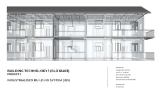
- 1. BUILDING TECHNOLOGY 1 (BLD 61403) PROJECT 1 INDUSTRIALISED BUILDING SYSTEM (IBS) PREPARED BY: Dayang Nadrah (0323741) Low Chi Yin(0329147) Neville Geoffrey (0317780) Nurul Shahira (0326500) Vincentia Mutiara Kartika (0303496) PREPARED FOR: Ar Edwin Chan
- 2. CONTENTS 1.0 Introduction to IBS 1.1 System Comparison 1.2 Equipments Needed 2.0 Precedent Study 3.0 Proposed Building Systems 3.1 Precast System 3.1.1 Precast Column 3.1.2 Precast Beam 3.1.3 Precast Slab 3.1.4 Precast Wall 3.1.5 Precast Staircase 3.1.6 Precast Balcony 3.2 Steel Framing System 3.2.1 Steel Roof Truss 3.3 Blockwork System 3.3.1 Blockwork Wall 4.0 Schedule of Modular Components 5.0 IBS Score Calculation 5.1 Calculation 6.0 Working Drawings 7.0 Construction Process 8.0 References
- 3. 1.0 IBS SYSTEM The Industrialized Building System (IBS) was first introduced to Malaysia in the 1960s. IBS is a construction process that utilizes techniques, components, products or building system which involve prefabricated component and on-site installation. Open System - Components can be joined with other components that are pre- fabricated from different manufacturers. Close System- Can only be joined with the components manufactured by the same manufacturer. Five types of IBS used in Malaysia; Precast System Precast column, beams, slab, wall, 3D components (staircase, toilets, balconies, lift chambers) Steel Framing System Steel beams and columns, portal frames, roof trusses Prefabricated Timber Framing Timber frames, roof trusses Formwork System Steel formworks, tunnel forms, beams and columns molding forms Blockwork System Interlocking concrete masonry unit (CMU), lightweight concrete blocks ADVANTAGES 1. Minimized the number of labour needed to construct the building due to simplified construction methods. 2. Reduce construction time due to the usage of standardized and simplified components 3. Environmental friendly as less use of formworks on site 4. Lower total construction cost DISADVANTAGES 1. Lack of aesthetic value due to standardized of components. IBS buildings are mostly similar 2. Bad workmanship might caused problems on the joinery part 3. Lack of experience practicing or designing IBS by contractors or consultants. INTRODUCTION Figure 1.0.1 Construction process using prefabricated components or IBS
- 4. 1.1 IBS SYSTEM INDUSTRIALISED BUILDING SYSTEM (IBS) ● Building components are manufactured in a factory then shipped to the site to be constructed ● Cleaner construction process ● Lesser skilled labor needed ● Faster construction process as components are pre-fabricated at the factory ● No space requirement for fabrication ● Higher industrialized quality CONVENTIONAL BUILDING SYSTEM ● Building components are fabricated and constructed on site ● No transportation ● Proper, large free space required ● Alot of formwork and waste from construction process ● More labor needed ● Longer construction time. Construction depends on weather, if the weather is not good, construction might stop and it takes longer time for fabricated components to be dried. COMPARISON OF THE TWO SYSTEMS Figure 1.1.1 Prefabricated components Figure 1.1.2 On-site fabrication
- 5. 1.2 IBS SYSTEM EQUIPMENT NEEDED Cranes Crane is a machine used to lift heavy components and transporting them to other place or level. Lifting Tools Lifting tools or also known as lifting gear is an equipment attached to the crane that can be used to lift and lowering loads of the pre-fabricated components. Rigging Tools Rigging tools (eg. Hook) is attached to the crane to carry the lifting tools Figure 1.2.1 Mobile Crane Figure 1.2.2 Tower Crane (Min. 3 Stories High) Figure 1.2.3 Spreader Beams Figure 1.2.4 Wire Rope Slings Figure 1.2.5 Hook for the crane Figure 1.2.6 Shackles (Lifting point) Figure 1.2.7 Eye bolt (Lifting point)
- 6. 2.0 PRECEDENT The Seri Jati Apartment located at Setia Alam,Shah Alam is classified as a low-cost affordable apartment. The project is developed under the guidance of SP Setia. Consist of 948 Units, a total of 6 blocks with the maximum height of 10 Storey Apartment in a single phase development. Reclines across an 18 acres land area with a built-up area of 813 sqft t. Provided it has two parking spots with 2 elevators. Figure 2.0.2 Seri Jati Layout Plan (6 Blocks) Figure 2.0.3 Seri Jati Block Layout - Typical Floor Plan SERI JATI APARTMENT, SETIA ALAM, MALAYSIA Figure 2.0.1 View of Seri Jati Apartment
- 7. 2.0 PRECEDENT SERI JATI APARTMENT, SETIA ALAM, MALAYSIA Figure 2.0.4 Seri Jati Isometric Construction system includes few conventional construction for foundation, ground floor, transfer beam and RC slab as well as various precast components such as, precast load bearing and non bearing wall, Precast staircases and landing slabs, precast lift core walls, Precast bathroom slabs and precast air cond ledges. The roofing uses prefabricated steel roof trusses. Figure 2.0.6 IBS Score for Seri Jati Apartment Figure 2.0.5 Construction Progress of Seri Jati END RESULT 1. No columns and projected beams 2. Consistent squareness 3. Consistent quality
- 8. Proposed Components 1. Precast Column 2. Precast Beam 3. Precast Slab 4. Precast Staircase 5. Precast Balcony 6. Precast Wall (External) 7. Blockwork Wall (Internal) 8. Prefabricated Steel Roof Trusses 3.0 PROPOSED BUILDING SYSTEMS Figure 3.0.1 The Look of Proposed Building
- 9. 3.1 PRECAST SYSTEM INTRODUCTION The concept of precast (also known as “prefabricated”) construction includes those buildings, where the majority of structural components are standardized and produced in plants in a location away from the building, and then transported to the site for assembly. These components are manufactured by industrial methods based on mass production in order to build a large number of buildings in a short time at low cost. ADVANTAGES 1. Very rapid speed of erection 2. Entire building can be precast 3. High quality controlled (Everything produced in factories standard) 4. Prestressing is easily done which can reduce the size and number of the structural members DISADVANTAGES 1. Skilled labour is required in the application of the components on site 2. Heavy machineries are needed to carry the components Suitability 1. High rise - Most of components are the same, precast system is suitable for this type of projects due to uniformity and fast installation 2. Developer housing - Design of houses from developers are mostly identical, using precast system for this project type will save time in construction time also labour cost 3. Low cost building - Lesser construction cost and labour Figure 3.1.1 Manufacturing Process of Precast Components
- 10. 3.1 PRECAST SYSTEM INTRODUCTION MANUFACTURING PROCESS 1 2 3 4 5 6 The precast factory often has specialist workshops for the manufacture and maintenance of moulds, and for the production of jig- built reinforcing cages and connections. The reinforced cage is positioned in the partly assembled mould, then the remaining mould section is completed. Carefully specified concrete is placed into the mould. Many precast works now employ computer controlled batching plants. To ensure that optimum density is obtained and that specified strengths are achieved, concrete is placed and compacted using high-frequency external vibrators or pokers. Once an appropriate strength has been reached, the precast units are moved to the storage area. The components are delivered to site in a predetermined sequence to ensure that hardened concrete are ready for instant erection. The components are erected straight from the lorry
- 11. 3.1 PRECAST SYSTEM INTRODUCTION FABRICATION PROCESS 1 2 3 4 5 6 Level and flatness of the base mould should be checked before assembling the mould for panel casting. Ensure that the dimensions of mould are within specified tolerance. The mould should be clean and free from debris and old mortars using remover or scaling bars. Checking that the riber size ,spacing and lap length are accordance with the drawings. Check that the concrete grade used is according to design specification. Proper vibration and compaction should be carried out in more congestion areas. Adequate curing time should be observed and desired environment. Depending on the anchor length of inserts and type of precast elements ie thin floor slabs the minimum concrete strength required may be higher to overcome the suction and friction forces during demoulding.
- 12. 3.1.1 PRECAST SYSTEM PRECAST COLUMN (STACKED COLUMN) Precast Columns can be single-tier or multi-tiered as required. Use of precast columns will expedite the project, as there is no requirement to wait for the curing as there is with cast-in-situ columns. Column connections are often made using grouted sleeves, but bolted or socket connections are also used. DESIGN PROTOCOLS 1. Complete Customization 2. Multiple Applications 3. Rapid and precision structure installation Figure 3.1.1.1 Precast columns on site ADVANTAGES 1. Can be customized and designed to any specifications and fittings 2. Suitable for uniform construction finishes 3. Constructed 5 times faster than on site columns Types of Precast Columns Corner Column Extended Column Stacked Column
- 13. 3.1.1 PRECAST SYSTEM PRECAST COLUMN (STACKED COLUMN) Figure 3.1.1.2 Base connector Figure 3.1.1.3 Column to column connector 1. Metal bearing plates and embedded anchor bolts are cast into the ends of the columns. 2. After the columns are mechanically joined, the connection is grouted to provide full bearing between elements and protect metal components from fire and corrosion. CONSTRUCTION SYSTEM Ways to connect precast Columns to Foundation 1. Socket Connection 2. Starter Bars 3. Bolted Connection Ways to connect precast column to column One Typical Column-to-Column Connection with Grout beneath the Base Plate. 1. Column to column stacked 2. Column to column through beam connection
- 14. 3.1.2 PRECAST SYSTEM PRECAST BEAMS (T-SECTION AND L-SECTION) Precast Beams provide a flexible solution to the structural component of your project. Precast Beams can be used for a number of applications from parking structures to the structural framework of commercial buildings. Precast beams are perfect for underground parking structures where the efficiency of the floor utilization can be increased, reducing the size of the lot needed. Beams create an ideal framework for hanging Precast Structural and Architectural Wall Panels and setting Hollow core floors or solid slabs. Figure 3.1.2.1 Precast beams joined with the columns Types of Beam DESIGN PROTOCOL 1. Require complex formwork to bear the weight of fresh concrete. 2. 7~28 days, so that concrete gains strength and carry the self load 3. This formwork requires time to erect and involves material inventory and also large man power. These are angled notched beam that support stadium riser unit. These are beams cast with an integral balcony. Span over door or window opens, to provide bearing for structure above. Raker beam Balcony beam Lintel Beam span around perimeter to provide a bearing edge on one side for flooring slabs and structure above ADVANTAGES 1. Quality The beam undergo effective curing and monitoring which makes it high level of quality unlike on site pouring which is affected by dust. 2. Long life and low maintenance Eliminates problem of leakage, cracks and reduces maintenance cost.. 3. Easy Installation. 4. Energy efficient and recyclable.
- 15. 3.1.2 PRECAST SYSTEM PRECAST BEAMS Figure 3.1.2.1 Beams to Column Connection 1. Beams are set on bearing pads on the column corbels. 2. Steel angles are welded to metal plates cast into the beams and columns and the joint is grouted solid CONSTRUCTION SYSTEM Beam to column pin connection Beam to column welded Bolted beam to column connection End to end Beam to column connection
- 16. 3.1.3 PRECAST SYSTEMPRECAST SLABS (HOLLOW CORE SLAB) Figure 3.1.3.1 Types of precast slab ADVANTAGES 1. Durable With properties of high strength, low porosity and protection from the prestressing reinforcement, they are long lasting units which consume lesser maintenance 1. Sound Proof Construction Good sound insulation property Types of Precast Slabs 1. Solid flat slab 2. Hollow core slab 3. Double Tee 4. Single Tee Hardly any building materials available today offer the economy, flexibility and reliability of precast, prestressed concrete. These slab units can be manufactured in various depths in order to fulfill the diverse requirements for span and loading. Precast hollow core slabs are typically 1200mm in width and about 20000mm in length. DESIGN PROTOCOLS 1. Providence of standard span/ ratio depth to ease transportation and lifting. 2. Precast frames should be equivalent to cast-in-situ frames. 3. Design custom to service load or seismic load. 4. Sufficient cover thickness for fire resistance.
- 17. 3.1.3 PRECAST SYSTEM PRECAST SLABS CONSTRUCTION SYSTEM 1. Slabs are set on bearing pads on precast beams. 2. Steel reinforcing bars are in inserted into the slab keyways yo span the joint. 3. The joint is grouted solid 4. The slab may remain untopped as shown (figure 3.13.2), or topped with several inches of cast in place concrete Figure 3.1.3.2 Slabs to Beams Connection Figure 3.1.3.3 Setting a Solid Slab on Beams Figure 3.1.3.4 Grouting Process
- 18. 3.1.4 PRECAST SYSTEM PRECAST WALLS A method where concrete are molded into panels and are cured in a controlled environment that then are brought to construction site to be assembled. ADVANTAGES 1. Time saving for construction period 2. Rigid component that give a better strength for the structure 3. Water and fire resistance high DISADVANTAGES 1. Can not be customized on renovation after construction. - Precast concrete solid - Precast concrete thin-shell panel - Precast concrete sandwich wall panel Types of Precast Walls
- 19. 3.1.5 PRECAST SYSTEM PRECAST STAIRCASE Precast concrete staircase is an ideal solution in constructing similar and repetitive concrete staircase in a building. Precast concrete staircases are cast on their sides or face down using mould with a fixed tread and riser. The quality of end product is then assured. Figure 3.1.5.1 Precast Staircase Being Installed ADVANTAGES 1. Speed in installation and reduction in overall job 2. Rigid structure eliminates movement and possibility to creaks 3. Extended landing can be produced with variable length 4. Installation is not affected by adverse weather conditions DISADVANTAGES 1. Efficient transport and lifting are prerequisite 2. Additional care is needed to achieve monolithic joints between precast stairs and the cast in situ structure. Types of Precast Stairs DESIGN PROTOCOLS 1. Riser height should be limited to 165mm and 175mm 2. Recommended width of a standard staircase is to allow for a 100mm clearance between handrails. 3. Are cast on their sides of face down using precision-engineered steel mould and groove lines. 4. Should be suitable for fire escape. - Precast concrete straight flight stairs - Precast concrete cranked slab stairs - Precast concrete open riser stairs - Precast concrete spiral stairs
- 20. 3.1.5 PRECAST SYSTEM PRECAST STAIRCASE CONSTRUCTION SYSTEM 1. Hoist using a crane with four chains complete with shortening clutches (Figure 3.1.4.2) 1. The type and size of cast in lifting points may vary 2. Plastic shims can be used as necessary to achieve correct level 3. Before installation, ensure that the bearing points are prepared and ready for placement 4. All debris should be cleared from the stair so that no obstructions remain 5. Ensure any load bearing block work is at least 72 hours old and steelwork is lined and leveled with bases grouted. 6. For installation, the stairs unit should be lifted upright, in the position that they are going to be lifted. Figure 3.1.5.2 Attaching U-Shaped Precast Stairs to Slab Figure 3.1.5.3 Joinery System
- 21. 3.1.6 PRECAST SYSTEM PRECAST BALCONY Having a well designed balcony helps to change the face of how a building will look. Balconies are attached at height giving the benefit of providing extra outside space and, at the same time, creating a visual feature to a façade Figure 3.1.6.1 Uninstalled Precast Balcony ADVANTAGES 1. Rain water outlets can be incorporated into the finished balcony 2. Balconies can be erected with floor units prior to pouring screed 3. Ease of speed erection Types of Precast Balcony 1. Cantilevered, 2. Fully supported or 3. Flying DESIGN PROTOCOLS 1. Formstress to provide reinforcing starters for the nibs and they be cast on site. 2. The cantilever steel can be cut short and Reidbar couplers fitted on site. 3. Ensure chains and strops are of the correct length and not more than 30 degrees of vertica DISADVANTAGES 1. Very small margin for error 2. Connections may be difficult 3. Economics of scale demand regularly shaped buildings. 4. Cranes are required to lift panels
- 22. 3.2 STEEL FRAMING SYSTEM INTRODUCTION Steel framing system describes the the fabrication and erection of a steel skeleton using vertical columns and horizontal beams. Steel is used more frequently in construction, and is far more common in residential building. They are normally combined with concrete floors or brick walls. The steel skeleton would than act as the main supporting element of the structure. Usage of steel framing system in construction includes steel beams and column, portal frames, roof trusses and more. Figure 3.2.1 Steel Framing Construction ADVANTAGES 1. A sustainable option for low-rise, mid-rise and high-rise building projects. 2. Easily erected once steel have been prefabricated. 3. Requires little maintenance and there are in no needs for treatment considering they are not subjected to insect infestations. 4. Recyclable, suitable for the environmentally conscious. DISADVANTAGES 1. Not heat resistant, there is potential of the members to weakening if subjected to heat in an extended period of time. 2. Steel framed buildings have a high level of sound transmission. 3. Requires heavy machinery and a special trades and skills. Types of Framing System 1. Skeleton Steel Framing 2. Wall Bearing Steel Framing 3. Long Span Framing a . Girders b. Truss c. Arches d. Rigid Frames DESIGN PROTOCOLS 1. Members shall be in good condition 2. Damage members to be replaced or repaired 3. Use of suitable type of fastener for different requirements.
- 23. 3.2 STEEL FRAMING SYSTEM INTRODUCTION MANUFACTURING PROCESS 1. Selection of raw material 1. Prepping of steel, shearing and punch press 1. Forming press is done using a press break for consistent and precise folding on frames as well as forming its final shape 1. Welding process of addition feature such as hinges and final welding is done to assemble and produce the frame. 1. Frame grinding and finishing is done by grounding and sanding. 1. Paint and bake depending on custom frame Figure 3.2.2 Raw material Figure 3.2.3 Forming press of steel Figure 3.2.4 Welding of frames Figure 3.2.5 Grinding of spot weld marks
- 24. 3.2.1 STEEL FRAMING SYSTEM STEEL ROOF TRUSSES A standard truss is a triangulated system that resist distortion due to its stable geometrical arrangement allowing even distribution of load across the members. A truss system comprised of 3 members, a top chord, a bottom chord and an interior members called webbing or webs. Majority of these roof trusses have webs that would run at an angle between top and bottom chords. The gable-end truss is to be supported along the entire length, and stabilized at the truss or wall intersection. Figure 3.2.1.1 Industrialised Steel Roof Figure 3.2.1.2 Standard Steel Roof Design Prefabricated steel trusses offer a high-strength, lightweight roof system that can be installed quickly. Most building roof can be framed with engineered light gauge steel trusses which are manufactured from c-shaped metal studs. Steel roof trusses can vary in design, an endless number of variation of the standard design are possible. Figure 3.2.1.3 Truss system ADVANTAGES 1. Suitable for low pitched roof 2. Sizes can be tailored 3. Easy assemble and disassemble, reduce carbon footprint 4. Long length high tensile metal roofing Types of Roof Trusses
- 25. 3.2.1 STEEL FRAMING SYSTEM STEEL ROOF TRUSSES CONSTRUCTION SYSTEM 1. Fabricators used several tool to cut the steel of a truss, with the help of plasma cutters, lasers and water jets. The metal fabricator punches holes using high-pressure notches. 1. After cutting is done, forming is proceeded using both pressing baking and rolling process. 1. Assembling process is welding pieces together to produces a steel truss. 1. Truss is install depending on design. Figure 3.2.1.4 Fabrication of steel trusses Figure 3.2.1.5 Welding process Figure 3.2.1.5 Trusses installation on site
- 26. 3.3 BLOCK WORK SYSTEM INTRODUCTION Blockwork system is a construction method that uses cement or concrete blocks. The blocks are made from cement, aggregates, water and admixtures where the ratio of the mixtures are adjusted according to requirements. These blocks are normally six times of clay brick size. Solid blocks Hollow blocks Cellular blocks Special blocks Solid piece of concrete casted without any holes on the surface. Normally is used on load bearing construction and exposed structures. Consists of one or more voids throughout the block to improve insulation capacity. Commonly used for exterior or retaining walls. Block with one and more voids that penetrate partially through the piece. Customized shape which has unique form and various dimensions compared to standard blocks for specific purpose. Types of Concrete Blocks Figure 3.3.1 Blockwork construction in progress MANUFACTURING PROCESS 1. Mixing all the materials consist of cement, aggregates, water and admixtures according to ratio and needs. 2. Molding Mixture is dumped into inclined bucket conveyor and transported to an elevated hopper. Mixture are compacted by hydraulic cylinder after second mixing process and then compacted again with vibration. Mixture is let dry for certain period. 3. Curing Low pressure steam kiln is being used in this process. The concrete blocks are being held in the room with adjusted temperature for about 24 hours. 4. Cubing Cured concrete blocks are split into parts according to standard size.
- 27. 3.3.1 BLOCK WORK SYSTEM BLOCKWORK WALL CONSTRUCTION METHODS 1. Prepare footing by using timber base to build the mold then pour concrete in it. . (Can be applied on precast beams.) 2. Spread mortar along corner to secure the positions of the concrete blocks 3. Set corner block to adjust the boundary and limits for the arrangement of the blocks. 4. Apply mortar around the base of concrete blocks being put to secure the stability more. 5. Lay concrete blocks from edge to another edge to make sure the arrangement of concrete blocks are correct. 6. Check alignment before stacking more concrete blocks any further. 7. Apply mortar on top of the first row of concrete blocks as joints between blocks. 8. Stack blocks on top of the mortar layer and repeat until certain height. 9. Add reinforcements such as metal bars to make the wall stronger and more rigid. ADVANTAGES 1. Cost efficient, less energy consumed and time saving 2. Excellent sound insulation. 3. Good option for dry lining wet finishes and fixing. DISADVANTAGES 1. Lower strength 2. Lower water resistance 3. Less load bearing properties due to limited storey of buildings application. Figure 3.3.2 Blockwork construction in progress
- 28. 4.0 SCHEDULE OF MODULAR COMPONENTS
- 29. 5.0 IBS SCORE CALCULATION ABOUT Ground floor = 312m2 First floor = 312m2 Second floor = 312m2 AREA OF CONSTRUCTION Columns : Precast concrete square columns ( m2) Beams : Precast concrete L-beams and T-beams ( Floor slabs : Precast Roof truss : Prefabricated steel roof trusses STRUCTURAL SYSTEMS Block work : WALL SYSTEM OTHER SIMPLIFIED CONSTRUCTION SOLUTION Columns : % Beams : % Floor slabs : % Roof truss : % Wall : % STRUCTURAL SYSTEM WALL SYSTEM OTHER The objective of the manual is to provide a well-structured assessment system for calculating the IBS Score. It sets out the IBS Score formula, the IBS Factor for each of the elements used in the building, methods of calculating the IBS Score, explanatory notes, as well as sample calculations. It is also intended to provide complete guidance for every professional to evaluate the IBS Score for any building project.
- 30. 5.1 IBS SCORE CALCULATION IBS SCORE CALCULATION PART 1 : STRUCTURAL SYSTEM Components Area IBS Factor Coverage IBS Score Ground Floor: Precast Concrete Columns Precast Concrete Beams Precast Solid Flat Slab 271.2m2 1.0 271.2/1084.8 12.5 First Floor: Precast Concrete Columns Precast Concrete Beams Precast Solid Flat Slab 271.2m2 1.0 271.2/1084.8 12.5 Second Floor: Precast Concrete Columns Precast Concrete Beams Precast Solid Flat Slab 271.2m2 1.0 271.2/1084.8 12.5 Roof: Prefabricated Steel Roof Trusses 271.2m2 1.0 271.2/1084.8 12.5 Total Part 1 1084.8m2 1 50
- 31. 5.1 IBS SCORE CALCULATION IBS SCORE CALCULATION PART 2 : WALL SYSTEM Components Length IBS Factor Coverage IBS Score Blockwork Wall System External Internal 69.2 62 1.0 69.2/131.2 62/131.2 20 Total Part 2 131.2 1 20 PART 3 : OTHER SIMPLIFIED CONSTRUCTION SOLUTIONS Components Coverage IBS Precast Concrete column usage MS 1064 part 10:2001 62.5% 2 Precast Concrete Beam usage MS 1064 10:2001 61.5% 2 Precast Slab usage MS 1064 10:2001 100% 4 Precast Blockwork Wall System usage 100% 4 Total Part 3 12
- 47. 8.0 REFERENCES 1. Precedent Studies, IBS Scoring in Malaysia, 25th April 2018, Available on http://rehdainstitute.com/wp-content/uploads/2017/05/4.-Kow-Choong-Ming.pdf 2. Steel Framing System, The Constructor Civil Engineering Home, 26th April 2018, Available on https://theconstructor.org/structural-engg/types-structural-steel-framing- systems/18554/ 3. Steel Framing System, Light Steel Framing Design System Standard, 26th April 2018, Available on https://kupce.ku.edu/sites/kupce.ku.edu/files/docs/cpep/structural/speaker-presentations-2017/LaBoube.pdf 4. Laboub. R, American Iron and Steel Institute retrieved from, https://www.wbdg.org/guides-specifications/building-envelope-design-guide/wall-systems/precast- concrete-wall-systems 5. Block work System, https://prezi.com/yvmdbgcguvay/blockwork-system/ 6. Block work System, https://www.slideshare.net/doogstone/blockwork
Editor's Notes
- WALL SYSTEM TO BE APPROVED
- DONE
- DONE
- DONE
- DONE http://rehdainstitute.com/wp-content/uploads/2017/05/4.-Kow-Choong-Ming.pdf
- DONE http://rehdainstitute.com/wp-content/uploads/2017/05/4.-Kow-Choong-Ming.pdf
- 3D PICTURE
- DONE
- DONE
- DONE
- DONE
- DONE
- DONE
- DONE
- DONE
- DONE
- DONE
- DONE
- DONE
- DONE
- DONE Hey Nadra whats means for design protocols? The design standards and requirements
- DONE
- DONE
- DONE
- LULU
- LULU
- DONE
- DONE
- ASHIN
- TAKE PICTURES OF CONSTRUCTING PROCESS