SlideShare a Scribd company logo
1 of 6
Download to read offline
Experiment
Objective:
Study of analog CRO and measurement of time periods and amplitude.
Equipment:
Function/Signal generator, CRO, BNC cables etc.
Theory:
The oscilloscope is the basic instrument for the study of all types of waveforms. It is
capable of generating a graph of an input signal versus time (Voltage-time mode), or a
second variable (X-Y mode). It can be employed to measure such quantities as peak
voltage, frequency or period, phase difference, pulse width, delay time, rise time and fall
time. Essentially, an oscilloscope consists of a cathode-ray tube (CRT), and its associated
control and input circuitry (a time-base generator, vertical and horizontal amplifiers) as
shown in Fig.1. In a conventional CRT tube, there are an electron gun, deflection plates
and the phosphorescent screen.
Principle of operation
The electron beam generated from an electron gun will be accelerated toward a
phosphorous screen by a potential difference between the electron gun and the screen. As
the beam emerges from the gun, it passes through a set of parallel plates (the vertical
deflection plates) oriented horizontally. The voltage to be displayed is amplified by a
vertical amplifier, and applied across these plates producing an electric field which deflects
the path of the electron vertically. The polarity of the signal of interest determines whether
the deflections will be up or down and the magnitude of the signal determines the amount
of vertical displacement of the electrons. Fig. 2 shows the deflection of an electron in a
uniform electric field.
After the beam has passed through the vertical deflection Plates, it passed through a second
set of similar plates that are oriented vertically. A potential difference applied to these
plates produce an electric field which deflects left or right. Under normal configuration
(one common exception is XY mode to be discussed later), these horizontal deflection
plates are connected to a time-base circuitry. This circuit can control how fast the electron
beam sweeps from the left to right (use Sweep Knob). Adjusting the sweep speed, the
resulting trace on the screen can be spread out or compressed. If the two deflection
voltages were held constant, the electron beam would strike a fixed point on the
phosphorescent film and a stationary point would be visible on the screen. However, most
voltages of interested are time-varying and so the voltage applied to the Horizontal
deflection plates is varied with time in such a way that the spot moves from left to right
on the screen as time passes. Since the phosphorescent material has the property of
emitting light for several milliseconds after the electrons have passed, the total effect is
for the electrons to leave behind a visible trail –a time-varying signal. The horizontal
deflection voltage (of “sweep voltage”) is also varied in such a way that when the beam
reaches the right-hand edge of the screen, it starts over at the left-right side. If the signal
to be displayed varies periodically in time, it is possible to synchronize the sweep voltage
with the signal so that the curve appears motionless on the screen. This is done with the
Trigger Level control which sets the oscilloscope to begin a trace when the voltage it
measures reaches a certain value. If a trace that is running across the screen can usually be
stabilized by adjusting the trigger level (as long as the waveform is periodic!).
Controls on the CRO front panel:
A. General
Intensity: Controls the intensity of the spot on the screen by controlling the number of
electrons allowed to pass to the screen
Focus: Controls the focusing of the electron beam.
X Shift / Y Shift: Changes the deflection voltages by a constant amount to shift the signal
vertically or horizontally.
B. Vertical Deflections Subsystem
Vertical sensitivity: Amplifier for the vertical deflection subsystem calibrated in ten-ns of
sensitivity. The input voltage can be determined from the deflection of the signal. For eg.,
if the vertical sensitivity is set at 50 mV/div and the vertical deflection is 4 div, then the
input voltage is 50 x 4 = 200 mV.
Var (Vldir): Vernier control for continuous vertical sensitivity.
Horizontal Deflection Subsystem
Sweep Time (Time/dir): Controls the sweep time for the spot to move horizontally across
one division of the screen when the triggered sweep mode is used.
Var (Time/div): Vernier control for continuous change of sweep time.
Trigger: Selects the source of the trigger signal, which produces the sweep waveform.
Internal Trigger: The output of the vertical amplifier is used to trigger the sweep
waveform.
External Trigger: An external signal must be applied to the X inputs to trigger the sweep
waveform.
Sweep Magnifier: Decreases the time per division of the sweep waveform.
Trigger Level: Selects amplitude point on trigger signal that causes sweep to start.
Trigger Mod:
AUTO provides normal triggering and provides baseline in absence of trigger signal.
NORM permits normal triggering but no sweep in absence of triggering. TV provides
triggering on TV field or TV line.
Procedure:
Voltage and Time period Measurement:
 Select the sine output of the signal generator, set at 1KHz
 Feed the signal to the vertical input of CRO.
 Adjust level and time base to get one or two cycles of the sine signal on the
oscilloscope, and calculate the vertical scale.
 Count the number of vertical divisions NV on the scope and find peak-peak level.
Vpp = NV X (Volts/Division)
Calculate Vrms as Vpp / 2√2
 Measure the signal with an AC milli voltmeter as well. It gives the rms value of the
signal.
 Measure the Time period ‘T’ of the signal by counting the number of horizontal
divisions.
 NH covering the span of one cycle.
T = NH X (Time/Division)
 Calculate the frequency as f = 1/T.
 Apply DC voltage from the regulated power supply and measure the DC level on
the scope.
Observations:
S.No.
Input Signal
Frequency (Hz)
t= Time
/Div
h= X-
division
T=t x h
(sec)
F= 1/T
(Hz)

More Related Content

What's hot

cathode ray oscilloscope &function generator
cathode ray oscilloscope &function generatorcathode ray oscilloscope &function generator
cathode ray oscilloscope &function generatormegha agrawal
 
Unit 1 static and dynamic
Unit 1 static and dynamicUnit 1 static and dynamic
Unit 1 static and dynamictamilnesaner
 
Double beam oscilloscope
Double  beam oscilloscopeDouble  beam oscilloscope
Double beam oscilloscopeB.k. Das
 
Electronic Measurement - Power Factor Meter
Electronic Measurement - Power Factor MeterElectronic Measurement - Power Factor Meter
Electronic Measurement - Power Factor MeterBurdwan University
 
Cathode Ray Oscilloscope CRO
Cathode Ray Oscilloscope CROCathode Ray Oscilloscope CRO
Cathode Ray Oscilloscope CROGulfam Hussain
 
Piezoelectric transducer
Piezoelectric transducerPiezoelectric transducer
Piezoelectric transducerArchi Jain
 
LISSAJOUS PATTERNS Experiment 3
LISSAJOUS PATTERNS Experiment 3LISSAJOUS PATTERNS Experiment 3
LISSAJOUS PATTERNS Experiment 3Karimi LordRamza
 
CATHODE RAY OSCILLOSCOPE (CRO)
CATHODE RAY OSCILLOSCOPE (CRO)CATHODE RAY OSCILLOSCOPE (CRO)
CATHODE RAY OSCILLOSCOPE (CRO)KumarSUshilSINGH
 
Capacitive transducers
Capacitive transducersCapacitive transducers
Capacitive transducersBalaganeshSomu
 
Transducers,Active Transducers and Passive Transducers
Transducers,Active Transducers and Passive TransducersTransducers,Active Transducers and Passive Transducers
Transducers,Active Transducers and Passive TransducersAL- AMIN
 
Presentaion on dual trace oscilloscope
Presentaion on dual trace oscilloscopePresentaion on dual trace oscilloscope
Presentaion on dual trace oscilloscopeAliya Sahir
 
procedure sheet for the experiment " SOLAR CELL"
procedure sheet for the experiment " SOLAR CELL"procedure sheet for the experiment " SOLAR CELL"
procedure sheet for the experiment " SOLAR CELL"salmansmd
 

What's hot (20)

cathode ray oscilloscope &function generator
cathode ray oscilloscope &function generatorcathode ray oscilloscope &function generator
cathode ray oscilloscope &function generator
 
Capacitive Type Transducer
Capacitive Type Transducer Capacitive Type Transducer
Capacitive Type Transducer
 
Unit 1 static and dynamic
Unit 1 static and dynamicUnit 1 static and dynamic
Unit 1 static and dynamic
 
Phototransistor
PhototransistorPhototransistor
Phototransistor
 
Double beam oscilloscope
Double  beam oscilloscopeDouble  beam oscilloscope
Double beam oscilloscope
 
Impulse Response ppt
Impulse Response pptImpulse Response ppt
Impulse Response ppt
 
Electronic Measurement - Power Factor Meter
Electronic Measurement - Power Factor MeterElectronic Measurement - Power Factor Meter
Electronic Measurement - Power Factor Meter
 
Cathode Ray Oscilloscope CRO
Cathode Ray Oscilloscope CROCathode Ray Oscilloscope CRO
Cathode Ray Oscilloscope CRO
 
Piezoelectric transducer
Piezoelectric transducerPiezoelectric transducer
Piezoelectric transducer
 
LISSAJOUS PATTERNS Experiment 3
LISSAJOUS PATTERNS Experiment 3LISSAJOUS PATTERNS Experiment 3
LISSAJOUS PATTERNS Experiment 3
 
CATHODE RAY OSCILLOSCOPE (CRO)
CATHODE RAY OSCILLOSCOPE (CRO)CATHODE RAY OSCILLOSCOPE (CRO)
CATHODE RAY OSCILLOSCOPE (CRO)
 
Transducers
TransducersTransducers
Transducers
 
Capacitive transducers
Capacitive transducersCapacitive transducers
Capacitive transducers
 
Power amplifiers
Power amplifiersPower amplifiers
Power amplifiers
 
Transducers,Active Transducers and Passive Transducers
Transducers,Active Transducers and Passive TransducersTransducers,Active Transducers and Passive Transducers
Transducers,Active Transducers and Passive Transducers
 
Recorder
RecorderRecorder
Recorder
 
Presentaion on dual trace oscilloscope
Presentaion on dual trace oscilloscopePresentaion on dual trace oscilloscope
Presentaion on dual trace oscilloscope
 
Tachometer
TachometerTachometer
Tachometer
 
procedure sheet for the experiment " SOLAR CELL"
procedure sheet for the experiment " SOLAR CELL"procedure sheet for the experiment " SOLAR CELL"
procedure sheet for the experiment " SOLAR CELL"
 
wave-propagation
wave-propagationwave-propagation
wave-propagation
 

Similar to Study of CRO and measusre the voltage and frequency

Cathode ray oscilloscope
Cathode ray oscilloscopeCathode ray oscilloscope
Cathode ray oscilloscopeesmaeel21
 
Handheld oscilloscopes, dso nano v3
Handheld oscilloscopes, dso nano v3Handheld oscilloscopes, dso nano v3
Handheld oscilloscopes, dso nano v3Md. Tosir Uddin
 
CRO-SARAVANA SELVI.pdf which is visualise the electrical signal into waveform
CRO-SARAVANA SELVI.pdf which is visualise the electrical signal into waveformCRO-SARAVANA SELVI.pdf which is visualise the electrical signal into waveform
CRO-SARAVANA SELVI.pdf which is visualise the electrical signal into waveformsivanandagouda57
 
CRO is the instrument that which visualise tha electrical signal into waveform
CRO is the instrument that which visualise tha electrical signal into waveformCRO is the instrument that which visualise tha electrical signal into waveform
CRO is the instrument that which visualise tha electrical signal into waveformsivanandagouda57
 
157929707-Presentation-on-Cro.pptx
157929707-Presentation-on-Cro.pptx157929707-Presentation-on-Cro.pptx
157929707-Presentation-on-Cro.pptxpranjalmishra68
 
Analog electronics LAB MANUAL
Analog electronics LAB MANUALAnalog electronics LAB MANUAL
Analog electronics LAB MANUALAJAL A J
 
Cro (emmi) (1)
Cro (emmi) (1)Cro (emmi) (1)
Cro (emmi) (1)Ravi Anand
 
Emicathoderayoscilloscope 120625075906-phpapp01
Emicathoderayoscilloscope 120625075906-phpapp01Emicathoderayoscilloscope 120625075906-phpapp01
Emicathoderayoscilloscope 120625075906-phpapp01HassanNawazish
 
Introduction to Oscilloscope and Function generator
Introduction to Oscilloscope and Function generatorIntroduction to Oscilloscope and Function generator
Introduction to Oscilloscope and Function generatorcyberns_
 
Method Of Measuring Projections Multi Function Using The Quick And Accurate O...
Method Of Measuring Projections Multi Function Using The Quick And Accurate O...Method Of Measuring Projections Multi Function Using The Quick And Accurate O...
Method Of Measuring Projections Multi Function Using The Quick And Accurate O...inventionjournals
 

Similar to Study of CRO and measusre the voltage and frequency (20)

Cathode ray oscilloscope
Cathode ray oscilloscopeCathode ray oscilloscope
Cathode ray oscilloscope
 
Handheld oscilloscopes, dso nano v3
Handheld oscilloscopes, dso nano v3Handheld oscilloscopes, dso nano v3
Handheld oscilloscopes, dso nano v3
 
CRO-SARAVANA SELVI.pdf which is visualise the electrical signal into waveform
CRO-SARAVANA SELVI.pdf which is visualise the electrical signal into waveformCRO-SARAVANA SELVI.pdf which is visualise the electrical signal into waveform
CRO-SARAVANA SELVI.pdf which is visualise the electrical signal into waveform
 
CRO is the instrument that which visualise tha electrical signal into waveform
CRO is the instrument that which visualise tha electrical signal into waveformCRO is the instrument that which visualise tha electrical signal into waveform
CRO is the instrument that which visualise tha electrical signal into waveform
 
157929707-Presentation-on-Cro.pptx
157929707-Presentation-on-Cro.pptx157929707-Presentation-on-Cro.pptx
157929707-Presentation-on-Cro.pptx
 
Analog electronics LAB MANUAL
Analog electronics LAB MANUALAnalog electronics LAB MANUAL
Analog electronics LAB MANUAL
 
Emi unit ii ppt
Emi unit ii pptEmi unit ii ppt
Emi unit ii ppt
 
Cro(nnm)
Cro(nnm)Cro(nnm)
Cro(nnm)
 
Cathode Ray Oscilloscope
Cathode Ray OscilloscopeCathode Ray Oscilloscope
Cathode Ray Oscilloscope
 
Cro (emmi) (1)
Cro (emmi) (1)Cro (emmi) (1)
Cro (emmi) (1)
 
CRO and FG.ppt
CRO and FG.pptCRO and FG.ppt
CRO and FG.ppt
 
Oscilloscope
OscilloscopeOscilloscope
Oscilloscope
 
Cro ppt
Cro pptCro ppt
Cro ppt
 
Oscilloscope
OscilloscopeOscilloscope
Oscilloscope
 
Ie practical file
Ie practical fileIe practical file
Ie practical file
 
Emicathoderayoscilloscope 120625075906-phpapp01
Emicathoderayoscilloscope 120625075906-phpapp01Emicathoderayoscilloscope 120625075906-phpapp01
Emicathoderayoscilloscope 120625075906-phpapp01
 
Oscilloscope tutorial
Oscilloscope tutorialOscilloscope tutorial
Oscilloscope tutorial
 
Introduction to Oscilloscope and Function generator
Introduction to Oscilloscope and Function generatorIntroduction to Oscilloscope and Function generator
Introduction to Oscilloscope and Function generator
 
Method Of Measuring Projections Multi Function Using The Quick And Accurate O...
Method Of Measuring Projections Multi Function Using The Quick And Accurate O...Method Of Measuring Projections Multi Function Using The Quick And Accurate O...
Method Of Measuring Projections Multi Function Using The Quick And Accurate O...
 
Method Of Measuring Projections Multi Function Using The Quick And Accurate O...
Method Of Measuring Projections Multi Function Using The Quick And Accurate O...Method Of Measuring Projections Multi Function Using The Quick And Accurate O...
Method Of Measuring Projections Multi Function Using The Quick And Accurate O...
 

Recently uploaded

Software and Systems Engineering Standards: Verification and Validation of Sy...
Software and Systems Engineering Standards: Verification and Validation of Sy...Software and Systems Engineering Standards: Verification and Validation of Sy...
Software and Systems Engineering Standards: Verification and Validation of Sy...VICTOR MAESTRE RAMIREZ
 
Concrete Mix Design - IS 10262-2019 - .pptx
Concrete Mix Design - IS 10262-2019 - .pptxConcrete Mix Design - IS 10262-2019 - .pptx
Concrete Mix Design - IS 10262-2019 - .pptxKartikeyaDwivedi3
 
HARMONY IN THE NATURE AND EXISTENCE - Unit-IV
HARMONY IN THE NATURE AND EXISTENCE - Unit-IVHARMONY IN THE NATURE AND EXISTENCE - Unit-IV
HARMONY IN THE NATURE AND EXISTENCE - Unit-IVRajaP95
 
Decoding Kotlin - Your guide to solving the mysterious in Kotlin.pptx
Decoding Kotlin - Your guide to solving the mysterious in Kotlin.pptxDecoding Kotlin - Your guide to solving the mysterious in Kotlin.pptx
Decoding Kotlin - Your guide to solving the mysterious in Kotlin.pptxJoão Esperancinha
 
APPLICATIONS-AC/DC DRIVES-OPERATING CHARACTERISTICS
APPLICATIONS-AC/DC DRIVES-OPERATING CHARACTERISTICSAPPLICATIONS-AC/DC DRIVES-OPERATING CHARACTERISTICS
APPLICATIONS-AC/DC DRIVES-OPERATING CHARACTERISTICSKurinjimalarL3
 
VICTOR MAESTRE RAMIREZ - Planetary Defender on NASA's Double Asteroid Redirec...
VICTOR MAESTRE RAMIREZ - Planetary Defender on NASA's Double Asteroid Redirec...VICTOR MAESTRE RAMIREZ - Planetary Defender on NASA's Double Asteroid Redirec...
VICTOR MAESTRE RAMIREZ - Planetary Defender on NASA's Double Asteroid Redirec...VICTOR MAESTRE RAMIREZ
 
main PPT.pptx of girls hostel security using rfid
main PPT.pptx of girls hostel security using rfidmain PPT.pptx of girls hostel security using rfid
main PPT.pptx of girls hostel security using rfidNikhilNagaraju
 
Electronically Controlled suspensions system .pdf
Electronically Controlled suspensions system .pdfElectronically Controlled suspensions system .pdf
Electronically Controlled suspensions system .pdfme23b1001
 
Heart Disease Prediction using machine learning.pptx
Heart Disease Prediction using machine learning.pptxHeart Disease Prediction using machine learning.pptx
Heart Disease Prediction using machine learning.pptxPoojaBan
 
Current Transformer Drawing and GTP for MSETCL
Current Transformer Drawing and GTP for MSETCLCurrent Transformer Drawing and GTP for MSETCL
Current Transformer Drawing and GTP for MSETCLDeelipZope
 
Internship report on mechanical engineering
Internship report on mechanical engineeringInternship report on mechanical engineering
Internship report on mechanical engineeringmalavadedarshan25
 
Microscopic Analysis of Ceramic Materials.pptx
Microscopic Analysis of Ceramic Materials.pptxMicroscopic Analysis of Ceramic Materials.pptx
Microscopic Analysis of Ceramic Materials.pptxpurnimasatapathy1234
 
Study on Air-Water & Water-Water Heat Exchange in a Finned Tube Exchanger
Study on Air-Water & Water-Water Heat Exchange in a Finned Tube ExchangerStudy on Air-Water & Water-Water Heat Exchange in a Finned Tube Exchanger
Study on Air-Water & Water-Water Heat Exchange in a Finned Tube ExchangerAnamika Sarkar
 
SPICE PARK APR2024 ( 6,793 SPICE Models )
SPICE PARK APR2024 ( 6,793 SPICE Models )SPICE PARK APR2024 ( 6,793 SPICE Models )
SPICE PARK APR2024 ( 6,793 SPICE Models )Tsuyoshi Horigome
 
Introduction to Microprocesso programming and interfacing.pptx
Introduction to Microprocesso programming and interfacing.pptxIntroduction to Microprocesso programming and interfacing.pptx
Introduction to Microprocesso programming and interfacing.pptxvipinkmenon1
 
Call Girls Narol 7397865700 Independent Call Girls
Call Girls Narol 7397865700 Independent Call GirlsCall Girls Narol 7397865700 Independent Call Girls
Call Girls Narol 7397865700 Independent Call Girlsssuser7cb4ff
 

Recently uploaded (20)

POWER SYSTEMS-1 Complete notes examples
POWER SYSTEMS-1 Complete notes  examplesPOWER SYSTEMS-1 Complete notes  examples
POWER SYSTEMS-1 Complete notes examples
 
Software and Systems Engineering Standards: Verification and Validation of Sy...
Software and Systems Engineering Standards: Verification and Validation of Sy...Software and Systems Engineering Standards: Verification and Validation of Sy...
Software and Systems Engineering Standards: Verification and Validation of Sy...
 
Concrete Mix Design - IS 10262-2019 - .pptx
Concrete Mix Design - IS 10262-2019 - .pptxConcrete Mix Design - IS 10262-2019 - .pptx
Concrete Mix Design - IS 10262-2019 - .pptx
 
★ CALL US 9953330565 ( HOT Young Call Girls In Badarpur delhi NCR
★ CALL US 9953330565 ( HOT Young Call Girls In Badarpur delhi NCR★ CALL US 9953330565 ( HOT Young Call Girls In Badarpur delhi NCR
★ CALL US 9953330565 ( HOT Young Call Girls In Badarpur delhi NCR
 
young call girls in Rajiv Chowk🔝 9953056974 🔝 Delhi escort Service
young call girls in Rajiv Chowk🔝 9953056974 🔝 Delhi escort Serviceyoung call girls in Rajiv Chowk🔝 9953056974 🔝 Delhi escort Service
young call girls in Rajiv Chowk🔝 9953056974 🔝 Delhi escort Service
 
HARMONY IN THE NATURE AND EXISTENCE - Unit-IV
HARMONY IN THE NATURE AND EXISTENCE - Unit-IVHARMONY IN THE NATURE AND EXISTENCE - Unit-IV
HARMONY IN THE NATURE AND EXISTENCE - Unit-IV
 
Decoding Kotlin - Your guide to solving the mysterious in Kotlin.pptx
Decoding Kotlin - Your guide to solving the mysterious in Kotlin.pptxDecoding Kotlin - Your guide to solving the mysterious in Kotlin.pptx
Decoding Kotlin - Your guide to solving the mysterious in Kotlin.pptx
 
APPLICATIONS-AC/DC DRIVES-OPERATING CHARACTERISTICS
APPLICATIONS-AC/DC DRIVES-OPERATING CHARACTERISTICSAPPLICATIONS-AC/DC DRIVES-OPERATING CHARACTERISTICS
APPLICATIONS-AC/DC DRIVES-OPERATING CHARACTERISTICS
 
VICTOR MAESTRE RAMIREZ - Planetary Defender on NASA's Double Asteroid Redirec...
VICTOR MAESTRE RAMIREZ - Planetary Defender on NASA's Double Asteroid Redirec...VICTOR MAESTRE RAMIREZ - Planetary Defender on NASA's Double Asteroid Redirec...
VICTOR MAESTRE RAMIREZ - Planetary Defender on NASA's Double Asteroid Redirec...
 
main PPT.pptx of girls hostel security using rfid
main PPT.pptx of girls hostel security using rfidmain PPT.pptx of girls hostel security using rfid
main PPT.pptx of girls hostel security using rfid
 
Electronically Controlled suspensions system .pdf
Electronically Controlled suspensions system .pdfElectronically Controlled suspensions system .pdf
Electronically Controlled suspensions system .pdf
 
Heart Disease Prediction using machine learning.pptx
Heart Disease Prediction using machine learning.pptxHeart Disease Prediction using machine learning.pptx
Heart Disease Prediction using machine learning.pptx
 
Current Transformer Drawing and GTP for MSETCL
Current Transformer Drawing and GTP for MSETCLCurrent Transformer Drawing and GTP for MSETCL
Current Transformer Drawing and GTP for MSETCL
 
Internship report on mechanical engineering
Internship report on mechanical engineeringInternship report on mechanical engineering
Internship report on mechanical engineering
 
Microscopic Analysis of Ceramic Materials.pptx
Microscopic Analysis of Ceramic Materials.pptxMicroscopic Analysis of Ceramic Materials.pptx
Microscopic Analysis of Ceramic Materials.pptx
 
Study on Air-Water & Water-Water Heat Exchange in a Finned Tube Exchanger
Study on Air-Water & Water-Water Heat Exchange in a Finned Tube ExchangerStudy on Air-Water & Water-Water Heat Exchange in a Finned Tube Exchanger
Study on Air-Water & Water-Water Heat Exchange in a Finned Tube Exchanger
 
SPICE PARK APR2024 ( 6,793 SPICE Models )
SPICE PARK APR2024 ( 6,793 SPICE Models )SPICE PARK APR2024 ( 6,793 SPICE Models )
SPICE PARK APR2024 ( 6,793 SPICE Models )
 
young call girls in Green Park🔝 9953056974 🔝 escort Service
young call girls in Green Park🔝 9953056974 🔝 escort Serviceyoung call girls in Green Park🔝 9953056974 🔝 escort Service
young call girls in Green Park🔝 9953056974 🔝 escort Service
 
Introduction to Microprocesso programming and interfacing.pptx
Introduction to Microprocesso programming and interfacing.pptxIntroduction to Microprocesso programming and interfacing.pptx
Introduction to Microprocesso programming and interfacing.pptx
 
Call Girls Narol 7397865700 Independent Call Girls
Call Girls Narol 7397865700 Independent Call GirlsCall Girls Narol 7397865700 Independent Call Girls
Call Girls Narol 7397865700 Independent Call Girls
 

Study of CRO and measusre the voltage and frequency

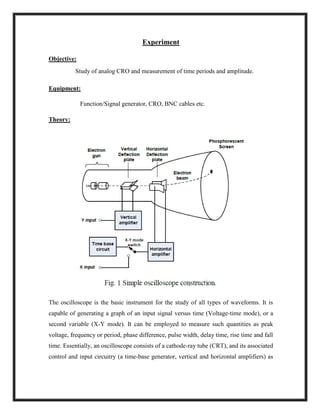
  • 1. Experiment Objective: Study of analog CRO and measurement of time periods and amplitude. Equipment: Function/Signal generator, CRO, BNC cables etc. Theory: The oscilloscope is the basic instrument for the study of all types of waveforms. It is capable of generating a graph of an input signal versus time (Voltage-time mode), or a second variable (X-Y mode). It can be employed to measure such quantities as peak voltage, frequency or period, phase difference, pulse width, delay time, rise time and fall time. Essentially, an oscilloscope consists of a cathode-ray tube (CRT), and its associated control and input circuitry (a time-base generator, vertical and horizontal amplifiers) as
  • 2. shown in Fig.1. In a conventional CRT tube, there are an electron gun, deflection plates and the phosphorescent screen. Principle of operation The electron beam generated from an electron gun will be accelerated toward a phosphorous screen by a potential difference between the electron gun and the screen. As the beam emerges from the gun, it passes through a set of parallel plates (the vertical deflection plates) oriented horizontally. The voltage to be displayed is amplified by a vertical amplifier, and applied across these plates producing an electric field which deflects the path of the electron vertically. The polarity of the signal of interest determines whether the deflections will be up or down and the magnitude of the signal determines the amount of vertical displacement of the electrons. Fig. 2 shows the deflection of an electron in a uniform electric field. After the beam has passed through the vertical deflection Plates, it passed through a second set of similar plates that are oriented vertically. A potential difference applied to these plates produce an electric field which deflects left or right. Under normal configuration (one common exception is XY mode to be discussed later), these horizontal deflection plates are connected to a time-base circuitry. This circuit can control how fast the electron beam sweeps from the left to right (use Sweep Knob). Adjusting the sweep speed, the resulting trace on the screen can be spread out or compressed. If the two deflection
  • 3. voltages were held constant, the electron beam would strike a fixed point on the phosphorescent film and a stationary point would be visible on the screen. However, most voltages of interested are time-varying and so the voltage applied to the Horizontal deflection plates is varied with time in such a way that the spot moves from left to right on the screen as time passes. Since the phosphorescent material has the property of emitting light for several milliseconds after the electrons have passed, the total effect is for the electrons to leave behind a visible trail –a time-varying signal. The horizontal deflection voltage (of “sweep voltage”) is also varied in such a way that when the beam reaches the right-hand edge of the screen, it starts over at the left-right side. If the signal to be displayed varies periodically in time, it is possible to synchronize the sweep voltage with the signal so that the curve appears motionless on the screen. This is done with the Trigger Level control which sets the oscilloscope to begin a trace when the voltage it measures reaches a certain value. If a trace that is running across the screen can usually be stabilized by adjusting the trigger level (as long as the waveform is periodic!). Controls on the CRO front panel: A. General Intensity: Controls the intensity of the spot on the screen by controlling the number of electrons allowed to pass to the screen Focus: Controls the focusing of the electron beam. X Shift / Y Shift: Changes the deflection voltages by a constant amount to shift the signal vertically or horizontally. B. Vertical Deflections Subsystem Vertical sensitivity: Amplifier for the vertical deflection subsystem calibrated in ten-ns of sensitivity. The input voltage can be determined from the deflection of the signal. For eg., if the vertical sensitivity is set at 50 mV/div and the vertical deflection is 4 div, then the input voltage is 50 x 4 = 200 mV. Var (Vldir): Vernier control for continuous vertical sensitivity.
  • 4. Horizontal Deflection Subsystem Sweep Time (Time/dir): Controls the sweep time for the spot to move horizontally across one division of the screen when the triggered sweep mode is used. Var (Time/div): Vernier control for continuous change of sweep time. Trigger: Selects the source of the trigger signal, which produces the sweep waveform. Internal Trigger: The output of the vertical amplifier is used to trigger the sweep waveform. External Trigger: An external signal must be applied to the X inputs to trigger the sweep waveform. Sweep Magnifier: Decreases the time per division of the sweep waveform. Trigger Level: Selects amplitude point on trigger signal that causes sweep to start. Trigger Mod: AUTO provides normal triggering and provides baseline in absence of trigger signal. NORM permits normal triggering but no sweep in absence of triggering. TV provides triggering on TV field or TV line. Procedure: Voltage and Time period Measurement:  Select the sine output of the signal generator, set at 1KHz
  • 5.  Feed the signal to the vertical input of CRO.  Adjust level and time base to get one or two cycles of the sine signal on the oscilloscope, and calculate the vertical scale.  Count the number of vertical divisions NV on the scope and find peak-peak level. Vpp = NV X (Volts/Division) Calculate Vrms as Vpp / 2√2  Measure the signal with an AC milli voltmeter as well. It gives the rms value of the signal.  Measure the Time period ‘T’ of the signal by counting the number of horizontal divisions.
  • 6.  NH covering the span of one cycle. T = NH X (Time/Division)  Calculate the frequency as f = 1/T.  Apply DC voltage from the regulated power supply and measure the DC level on the scope. Observations: S.No. Input Signal Frequency (Hz) t= Time /Div h= X- division T=t x h (sec) F= 1/T (Hz)