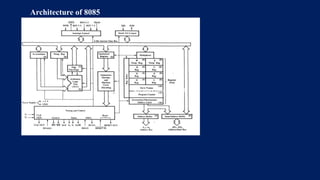
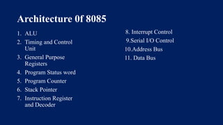
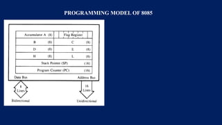
ARCHITECTURE OF 8085
MICROPROCESSOR
Dr.R.Hepzi Pramila Devamani,
Assistant Professor of Physics,
V.V.Vanniaperumal College for Women,
Virudhunagar.
Architecture 0f 8085
Architecture of 8085
Architecture 0f 8085
1. ALU
2. Timing and Control
Unit
3. General Purpose
Registers
4. Program Status word
5. Program Counter
6. Stack Pointer
7. Instruction Register
and Decoder
8. Interrupt Control
9.Serial I/O Control
10.Address Bus
11. Data Bus
PROGRAMMING MODEL OF 8085
REGISTERS
The Registers are of 8-bit & 16-bit size used
for different purposes
A- Accumulator – This is an special purpose
register. All the ALU operations are performed
with reference to the contents of Accumulator.
B,C,D,E,H,L – General purpose registers.
These registers can also used for 16-bit
operations in pairs. The default pairs
are BC, DE & HL.
F – Flag register – This register indicates the
status of the ALU operation.
PC – Program Counter – This is a 16-bit
register used to address the memory location from
where an instruction is going to be executed.
SP – Stack pointer - This is a 16-bit register
used to address the top of the stack memory
location.
Temporary register, W & Z – These registers
are only used by 8085 and are not available for
the programmer.
ALU – Arithmetic & Logic Unit
ALU of 8085 performs 8-bit arithmetic & logical
operations. The operations are generally performed
with Accumulator as one of the operands. The result
is saved in accumulator register.
Timing & Control Unit
This unit works as the brain of the CPU and
generates all the timing and control signals to
perform all the internal & external operations of the
CPU.
Instruction Decoder & Machine Cycle Encoder Unit
This unit decodes the op-code stored in the
Instruction Register (IR) and encodes it for the timing
& control unit to perform the execution of the
instruction.
THANK YOU

Microprocessor 8085 Architecture with functional block diagram.pptx

  • 1.
    ARCHITECTURE OF 8085 MICROPROCESSOR Dr.R.HepziPramila Devamani, Assistant Professor of Physics, V.V.Vanniaperumal College for Women, Virudhunagar.
  • 2.
  • 3.
    Architecture 0f 8085 1.ALU 2. Timing and Control Unit 3. General Purpose Registers 4. Program Status word 5. Program Counter 6. Stack Pointer 7. Instruction Register and Decoder 8. Interrupt Control 9.Serial I/O Control 10.Address Bus 11. Data Bus
  • 4.
  • 5.
    REGISTERS The Registers areof 8-bit & 16-bit size used for different purposes A- Accumulator – This is an special purpose register. All the ALU operations are performed with reference to the contents of Accumulator. B,C,D,E,H,L – General purpose registers. These registers can also used for 16-bit operations in pairs. The default pairs are BC, DE & HL.
  • 6.
    F – Flagregister – This register indicates the status of the ALU operation. PC – Program Counter – This is a 16-bit register used to address the memory location from where an instruction is going to be executed.
  • 7.
    SP – Stackpointer - This is a 16-bit register used to address the top of the stack memory location. Temporary register, W & Z – These registers are only used by 8085 and are not available for the programmer.
  • 8.
    ALU – Arithmetic& Logic Unit ALU of 8085 performs 8-bit arithmetic & logical operations. The operations are generally performed with Accumulator as one of the operands. The result is saved in accumulator register. Timing & Control Unit This unit works as the brain of the CPU and generates all the timing and control signals to perform all the internal & external operations of the CPU. Instruction Decoder & Machine Cycle Encoder Unit This unit decodes the op-code stored in the Instruction Register (IR) and encodes it for the timing & control unit to perform the execution of the instruction.
  • 9.