DSP
Digital signal processing(DSP) is the process of analyzing and
modifying a signal to optimize or improve its efficiency or
performance. It involves applying various mathematical and
computational algorithms to analog and digital signals to produce a
signal that's of higher quality than the original signal.
OR
DSP is primarily used to detect errors, and to filter and compress
analog signals in transit. It is a type of signal processing performed
through a digital signal processor or a similarly capable device that
can execute DSP specific processing algorithms. Typically, DSP first
converts an analog signal into a digital signal and then applies signal
processing techniques and algorithms. For example, when
performed on audio signals, DSP helps reduce noise and distortion.
Some of the applications of DSP include audio signal processing,
digital image processing, speech recognition, biomedicine and
more.
3.
DSP manipulates differenttypes of signals with the
intention of filtering, measuring, or compressing and
producing analog signals.
Analog signals differ by taking information and translating it
into electric pulses of varying amplitude, whereas digital
signal information is translated into binary format where
each bit of data is represented by two distinguishable
amplitudes.
Another noticeable difference is that analog signals can be
represented as sine waves and digital signals are
represented as square waves.
DSP can be found in almost any field, whether it's oil
processing, sound reproduction, radar and sonar, medical
image processing, or telecommunications-- essentially any
application in which signals are being compressed and
reproduced.
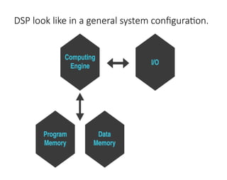
4.
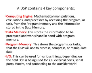
A DSP contains4 key components:
•Computing Engine: Mathematical manipulations,
calculations, and processes by accessing the program, or
task, from the Program Memory and the information
stored in the Data Memory.
•Data Memory: This stores the information to be
processed and works hand in hand with program
memory.
•Program Memory: This stores the programs, or tasks,
that the DSP will use to process, compress, or manipulate
data.
•I/O: This can be used for various things, depending on
the field DSP is being used for, i.e. external ports, serial
ports, timers, and connecting to the outside world.
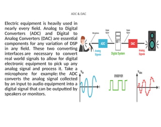
ADC & DAC
Electricequipment is heavily used in
nearly every field. Analog to Digital
Converters (ADC) and Digital to
Analog Converters (DAC) are essential
components for any variation of DSP
in any field. These two converting
interfaces are necessary to convert
real world signals to allow for digital
electronic equipment to pick up any
analog signal and process it. Take a
microphone for example: the ADC
converts the analog signal collected
by an input to audio equipment into a
digital signal that can be outputted by
speakers or monitors.
8.
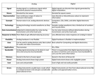
Analog Digital
Signal Analogsignal is a continuous signal which
represents physical measurements.
Digital signals are discrete time signals generated by
digital modulation.
Waves Denoted by sine waves Denoted by square waves
Representation Uses continuous range of values to
represent information
Uses discrete or discontinuous values to represent
information
Example Human voice in air, analog electronic devices. Computers, CDs, DVDs, and other digital electronic
devices.
Technology Analog technology records waveforms as they
are.
Samples analog waveforms into a limited set of numbers
and records them.
Data transmissions Subjected to deterioration by noise during
transmission and write/read cycle.
Can be noise-immune without deterioration during
transmission and write/read cycle.
Response to Noise More likely to get affected reducing accuracy Less affected since noise response are analog in nature
Flexibility Analog hardware is not flexible. Digital hardware is flexible in implementation.
Uses Can be used in analog devices only. Best suited
for audio and video transmission.
Best suited for Computing and digital electronics.
Applications Thermometer PCs, PDAs
Bandwidth Analog signal processing can be done in real
time and consumes less bandwidth.
There is no guarantee that digital signal processing can
be done in real time and consumes more bandwidth to
carry out the same information.
Memory Stored in the form of wave signal Stored in the form of binary bit
Power Analog instrument draws large power Digital instrument draws only negligible power
Cost Low cost and portable Cost is high and not easily portable
Errors Analog instruments usually have a scale which
is cramped at lower end and give considerable
observational errors.
Digital instruments are free from observational errors like
parallax and approximation errors.
9.
Signal
•Anything that carriesinformation can be called as
signal. It can also be defined as a physical quantity
that varies with time, temperature, pressure or with
any independent variables such as speech signal or
video signal.
•The process of operation in which the characteristics
of a signal (Amplitude, shape, phase, frequency, etc.)
undergoes a change is known as signal processing.
•Note − Any unwanted signal interfering with the main
signal is termed as noise. So, noise is also a signal but
unwanted.
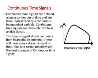
Continuous Time Signals
•Continuous-time signals are defined
along a continuum of time and are
thus, represented by a continuous
independent variable. Continuous-
time signals are often referred to as
analog signals.
• This type of signal shows continuity
both in amplitude and time. These
will have values at each instant of
time. Sine and cosine functions are
the best example of Continuous time
signal.
12.
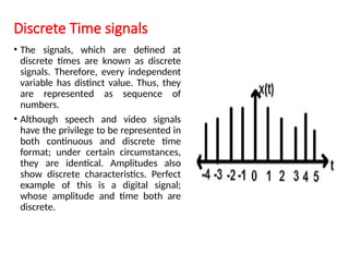
Discrete Time signals
•The signals, which are defined at
discrete times are known as discrete
signals. Therefore, every independent
variable has distinct value. Thus, they
are represented as sequence of
numbers.
• Although speech and video signals
have the privilege to be represented in
both continuous and discrete time
format; under certain circumstances,
they are identical. Amplitudes also
show discrete characteristics. Perfect
example of this is a digital signal;
whose amplitude and time both are
discrete.
13.
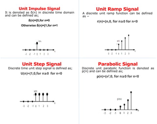
Unit Impulse Signal
Itis denoted as δ(n) in discrete time domain
and can be defined as;
(n)={0,for n=0
δ
Otherwise (n)={1,for n=1
δ
Unit Step Signal
Discrete time unit step signal is defined as;
U(n)={1,0,for n 0
≥ for n<0
Unit Ramp Signal
A discrete unit ramp function can be defined
as −
r(n)={n,0, for n 0
≥ for n<0
Parabolic Signal
Discrete unit parabolic function is denoted as
p(n) and can be defined as;
p(n)={n²,0, for n 0
≥ for n<0
14.
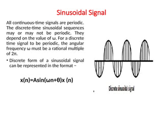
Sinusoidal Signal
All continuous-timesignals are periodic.
The discrete-time sinusoidal sequences
may or may not be periodic. They
depend on the value of ω. For a discrete
time signal to be periodic, the angular
frequency ω must be a rational multiple
of 2π.
• Discrete form of a sinusoidal signal
can be represented in the format −
x(n)=Asin(ωn+θ)x (n)
15.
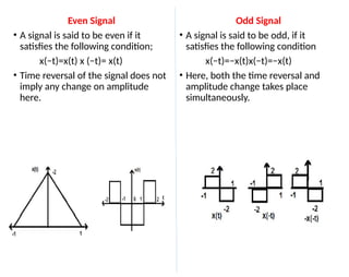
Even Signal
• Asignal is said to be even if it
satisfies the following condition;
x(−t)=x(t) x (−t)= x(t)
• Time reversal of the signal does not
imply any change on amplitude
here.
Odd Signal
• A signal is said to be odd, if it
satisfies the following condition
x(−t)=−x(t)x(−t)=−x(t)
• Here, both the time reversal and
amplitude change takes place
simultaneously.
16.
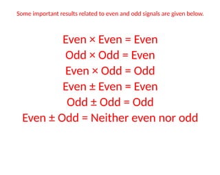
Some important resultsrelated to even and odd signals are given below.
Even × Even = Even
Odd × Odd = Even
Even × Odd = Odd
Even ± Even = Even
Odd ± Odd = Odd
Even ± Odd = Neither even nor odd
17.
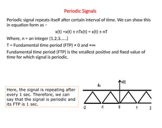
Periodic Signals
Periodic signalrepeats itself after certain interval of time. We can show this
in equation form as −
x(t) =x(t) ± nTx(t) = x(t) ± nT
Where, n = an integer (1,2,3……)
T = Fundamental time period (FTP) ≠ 0 and ≠∞
Fundamental time period (FTP) is the smallest positive and fixed value of
time for which signal is periodic.
Here, the signal is repeating after
every 1 sec. Therefore, we can
say that the signal is periodic and
its FTP is 1 sec.
18.
Non-Periodic Signal
•Simply, wecan say, the signals, which are not
periodic are non-periodic in nature. As obvious,
these signals will not repeat themselves after any
interval time.
•Non-periodic signals do not follow a certain format;
therefore, no particular mathematical equation can
describe them.
19.
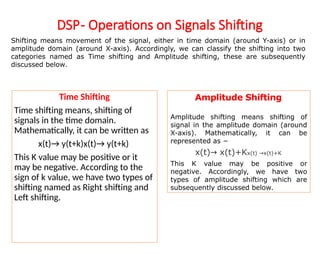
DSP- Operations onSignals Shifting
Time Shifting
Time shifting means, shifting of
signals in the time domain.
Mathematically, it can be written as
x(t)→ y(t+k)x(t)→ y(t+k)
This K value may be positive or it
may be negative. According to the
sign of k value, we have two types of
shifting named as Right shifting and
Left shifting.
Shifting means movement of the signal, either in time domain (around Y-axis) or in
amplitude domain (around X-axis). Accordingly, we can classify the shifting into two
categories named as Time shifting and Amplitude shifting, these are subsequently
discussed below.
Amplitude Shifting
Amplitude shifting means shifting of
signal in the amplitude domain (around
X-axis). Mathematically, it can be
represented as −
x(t) x(t)+K
→ x(t) x(t)+K
→
This K value may be positive or
negative. Accordingly, we have two
types of amplitude shifting which are
subsequently discussed below.
20.
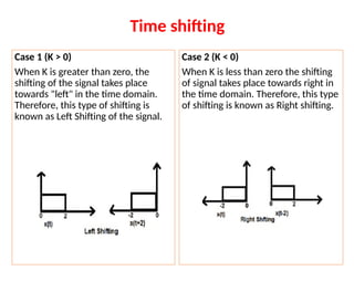
Case 1 (K> 0)
When K is greater than zero, the
shifting of the signal takes place
towards "left" in the time domain.
Therefore, this type of shifting is
known as Left Shifting of the signal.
Case 2 (K < 0)
When K is less than zero the shifting
of signal takes place towards right in
the time domain. Therefore, this type
of shifting is known as Right shifting.
Time shifting
21.
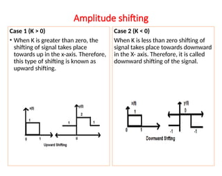
Amplitude shifting
Case 1(K > 0)
• When K is greater than zero, the
shifting of signal takes place
towards up in the x-axis. Therefore,
this type of shifting is known as
upward shifting.
Case 2 (K < 0)
When K is less than zero shifting of
signal takes place towards downward
in the X- axis. Therefore, it is called
downward shifting of the signal.