Download to read offline


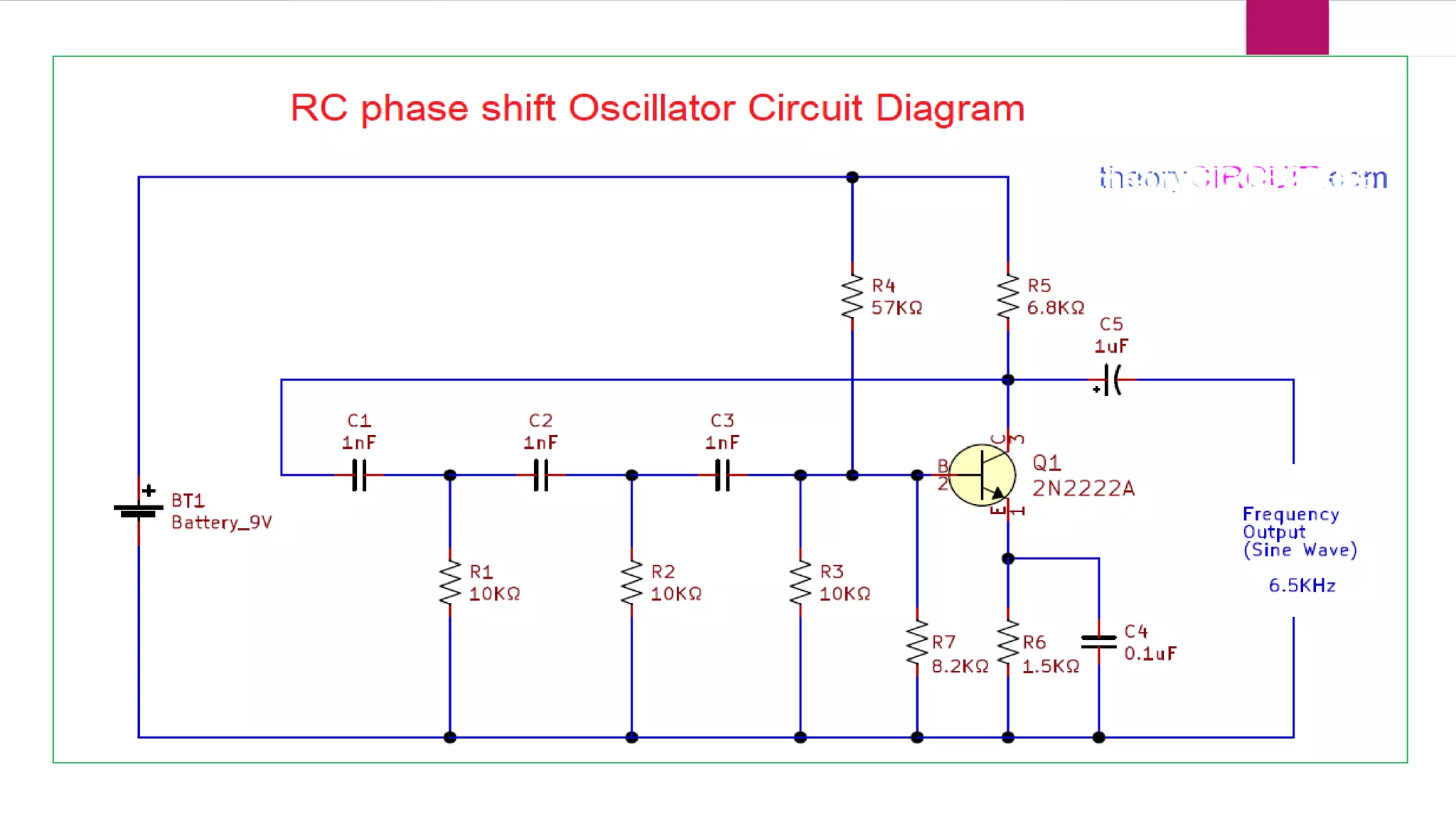
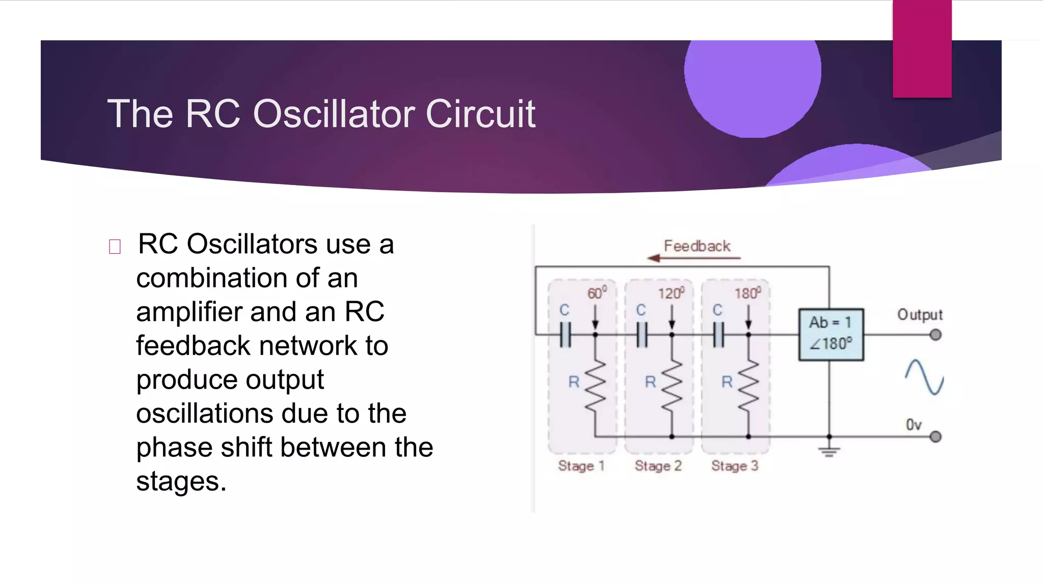
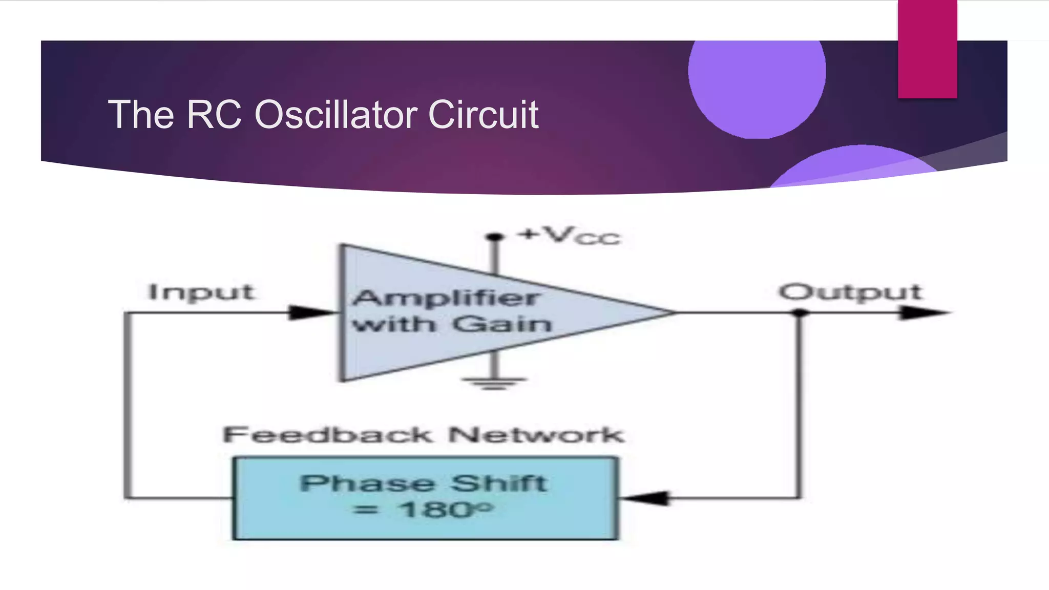


The RC oscillator circuit utilizes an amplifier and RC feedback network to create oscillations through phase shift. It requires sufficient positive feedback and loop gain to maintain continuous oscillation at a chosen frequency, typically ranging from 20-100 MHz, or even lower frequencies with variable resistors and capacitors. The frequency of oscillation is governed by the Barkhausen criterion, necessitating a total phase shift of 360° in the feedback loop with a loop gain of one.