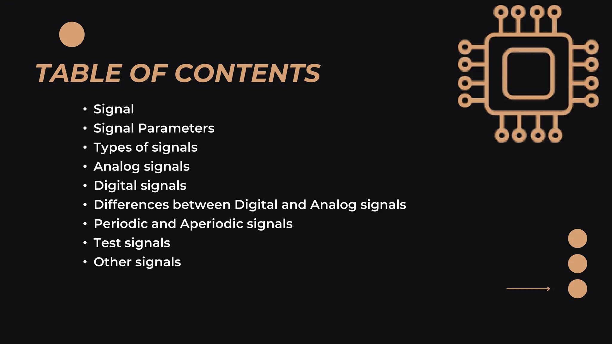
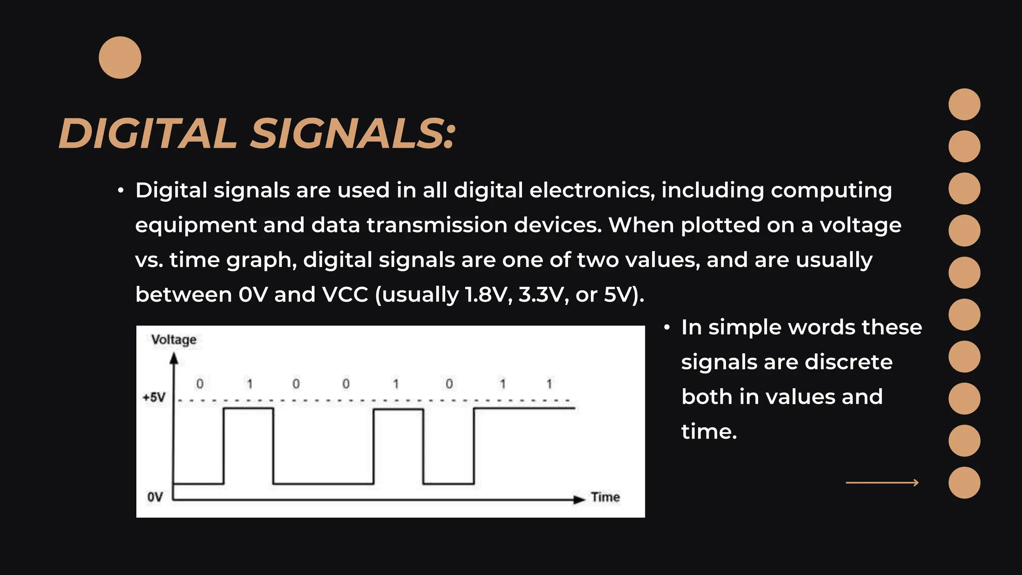
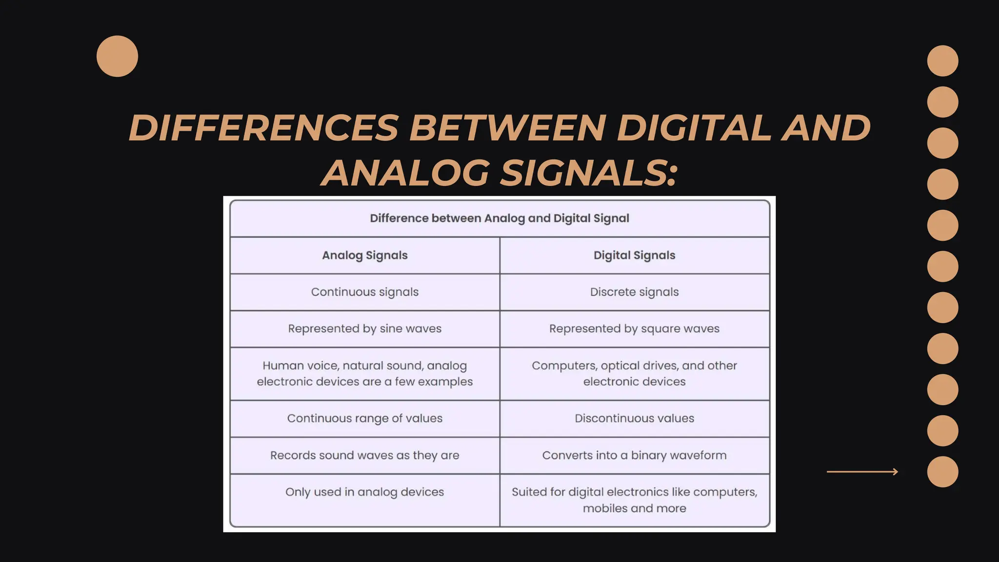
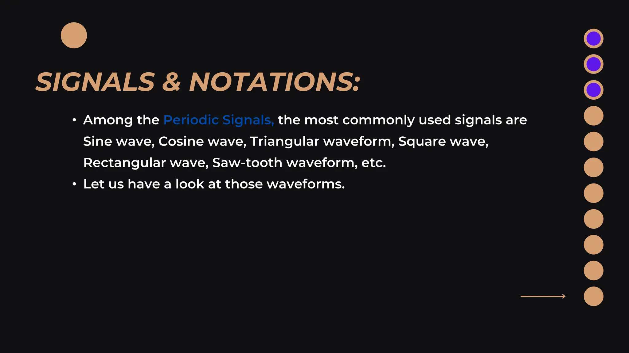
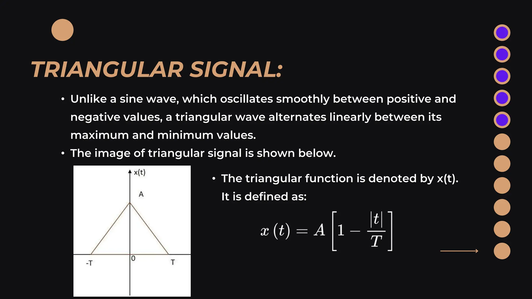
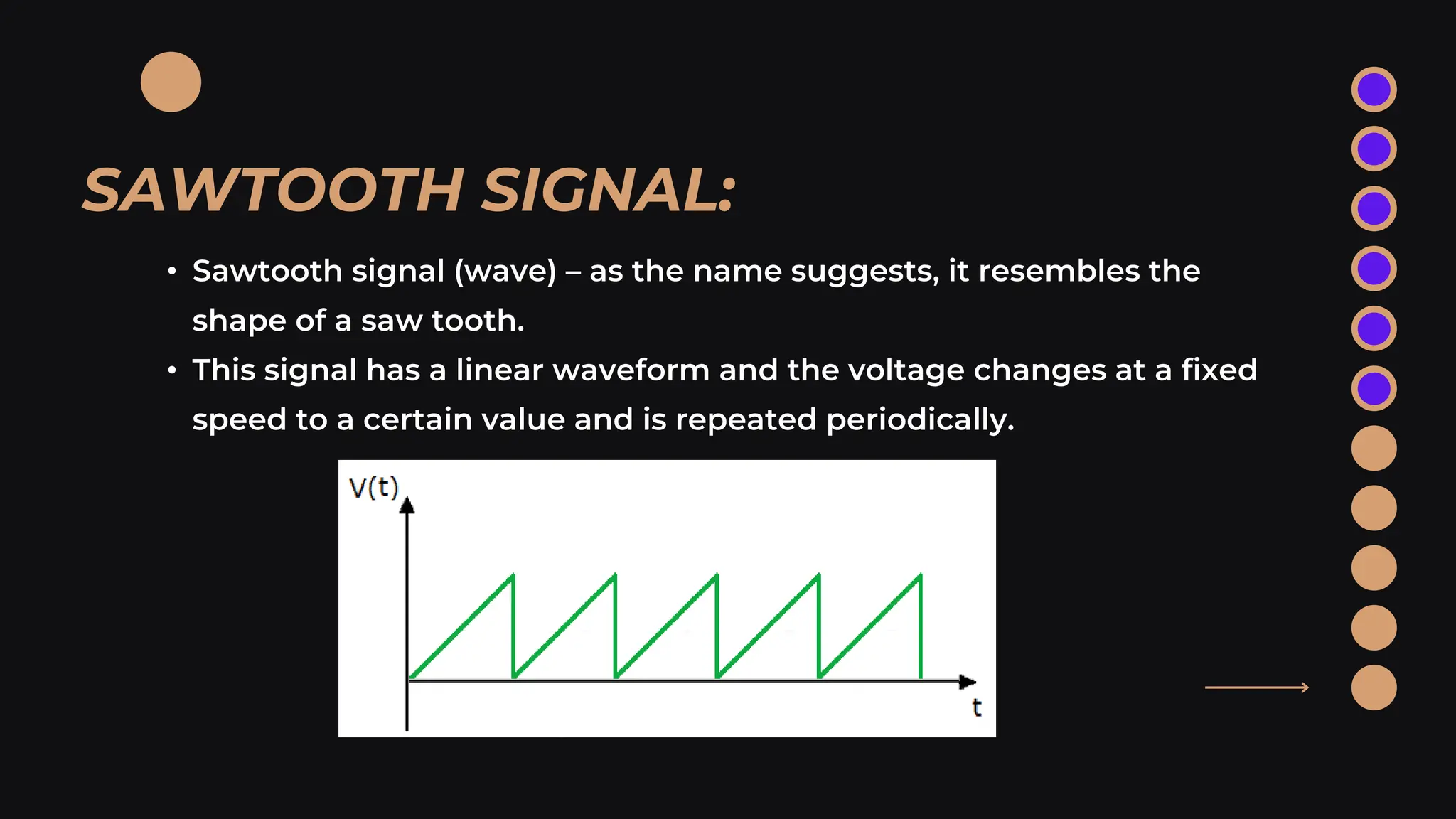
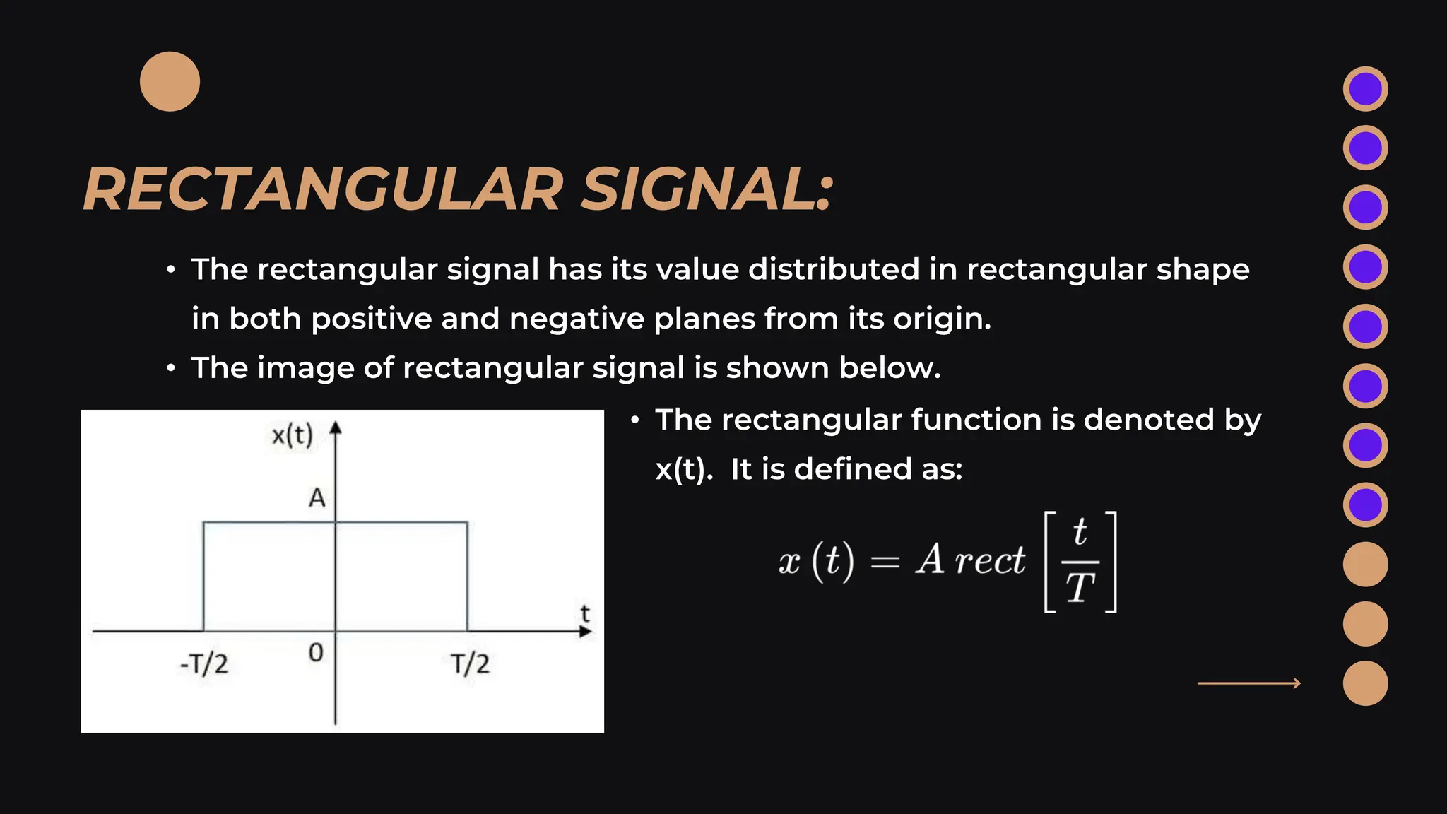
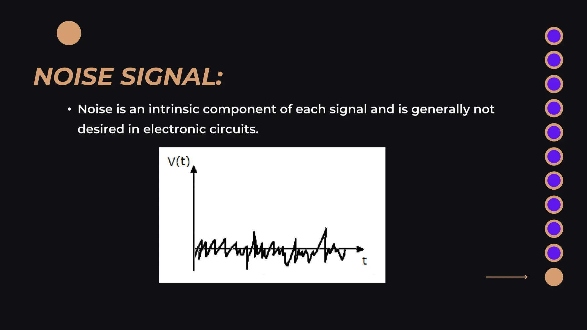
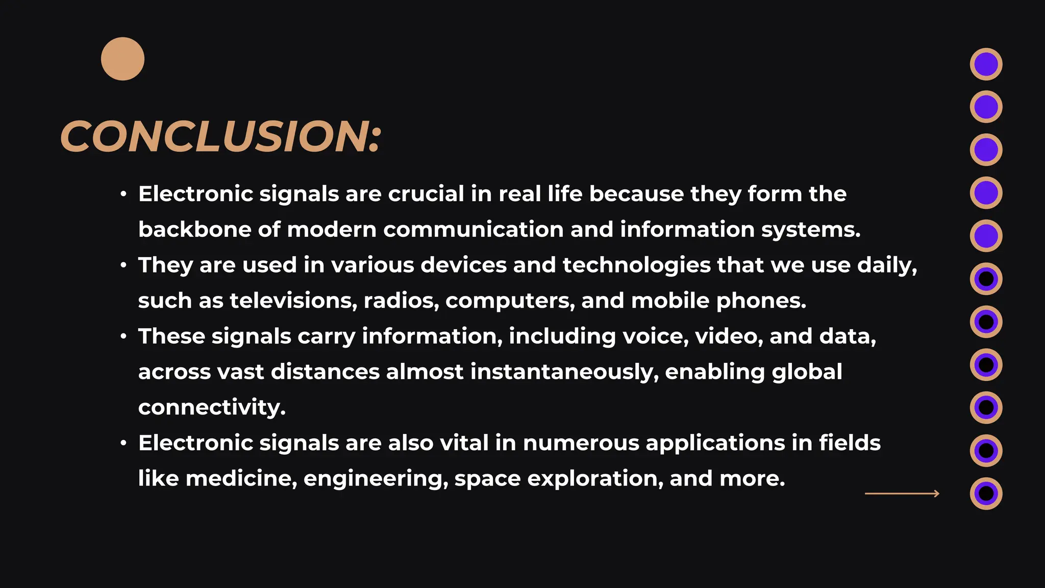
THIS PPT DISCUSSES ABOUT TYPES OF SIGNALS IN ELECTRONICS. IT ALSO INCLUDES ABOUT SIGNAL, DIFFERENCES BETWEEN FEW TYPES OF SIGNALS AND SOME EXAMPLES OF SIGNALS. IT ALSO HELP YOU UNDERSTAND THE IMPORTANCE OF SIGNAL IN DIALY LIFE.
4. • Signal
• Signal Parameters
• Types of signals
• Analog signals
• Digital signals
• Differences between Digital and Analog signals
• Periodic and Aperiodic signals
• Test signals
• Other signals
TABLE OF CONTENTS
5. • In electronics, a signal refers to any time-varying voltage, current, or
electromagnetic wave that carries information.
• Signals can carry different types of information such as electric,
magnetic, and acoustic signals.
• The most important signals in electronics are the changes in electric
charge, current, voltage, and electromagnetic field.
• They are used to analyze the behavior of electronic circuits or to
measure the changing electrical values.
SIGNAL:
6. SIGNAL PARAMETERS:
• Amplitude:
It refers to the maximum height of the signal waveform from it‘s
centerline. It indicates the strength of the signal. It varies with time.
• Frequency:
It refers to the rate at which a signal’s waveform repeats per second. It is
measured in hertz (Hz), where one hertz equals one cycle per second.
• Phase:
It describes the position of the waveform relative to time zero. It is
important in systems where signal timing is critical.
7. SIGNAL PARAMETERS:
• Pulse Width:
It is the duration of time that a pulse (rapid change in the signal’s
amplitude) is in a high (on) state.
• Period:
The period of a signal is the time it takes for the waveform to repeat
itself.
• Duty Cycle:
It is the percentage of one period in which a signal is active.
8. TYPES OF SIGNALS:
• Signals can be classified either as Analog or Digital, depending upon
their characteristics. Analog and Digital signals can be further
classified, as shown in the following image.
9. • A continuous time-varying signal, which represents a time-varying
quantity, can be termed as an Analog Signal.
• This signal keeps on varying with respect to time, according to the
instantaneous values of the quantity, which represents it.
• In simple words these signals are continuous both in values and time.
ANALOG SIGNALS:
10. • A digital signal is a signal that represents data as a sequence of
discrete values.
• It can only take on one value from a finite set of possible values at a
given time.
• With digital signals, the physical quantity representing the information
can be many things:
•Variable electric current or voltage
•Phase or polarization of an electromagnetic field
•Acoustic pressure
•The magnetization of a magnetic storage media
DIGITAL SIGNALS:
11. DIGITAL SIGNALS:
• Digital signals are used in all digital electronics, including computing
equipment and data transmission devices. When plotted on a voltage
vs. time graph, digital signals are one of two values, and are usually
between 0V and VCC (usually 1.8V, 3.3V, or 5V).
• In simple words these
signals are discrete
both in values and
time.
13. • Any analog or digital signal, that repeats its pattern over a period of
time, is called as a Periodic Signal.
• This signal has its pattern continued repeatedly and is easy to be
assumed or to be calculated.
PERIODIC SIGNAL:
14. • Any analog or digital signal, that doesn’t repeat its pattern over a
period of time, is called as Aperiodic Signal.
• This signal has its pattern continued but the pattern is not repeated
and is not so easy to be assumed or to be calculated.
APERIODIC SIGNAL:
15. • Among the Periodic Signals, the most commonly used signals are
Sine wave, Cosine wave, Triangular waveform, Square wave,
Rectangular wave, Saw-tooth waveform, etc.
• Let us have a look at those waveforms.
SIGNALS & NOTATIONS:
16. SINUSOIDAL SIGNAL:
• The Sinusoidal signal has its value varying sinusoidally from its origin.
• The image of Sinusoidal signal is shown below.
• The sinusoidal function is denoted by
x(t). It is defined as:
17. TRIANGULAR SIGNAL:
• Unlike a sine wave, which oscillates smoothly between positive and
negative values, a triangular wave alternates linearly between its
maximum and minimum values.
• The image of triangular signal is shown below.
• The triangular function is denoted by x(t).
It is defined as:
18. SAWTOOTH SIGNAL:
• Sawtooth signal (wave) – as the name suggests, it resembles the
shape of a saw tooth.
• This signal has a linear waveform and the voltage changes at a fixed
speed to a certain value and is repeated periodically.
19. SQUARE SIGNAL:
• Square Signal (wave) – similar to sine wave, it is described by two
parameters: amplitude and frequency, with the difference that the
RMS voltage value for the square wave is equal to its amplitude.
Frequency “f” is often replaced by the period “T” which equals to:
20. RECTANGULAR SIGNAL:
• The rectangular signal has its value distributed in rectangular shape
in both positive and negative planes from its origin.
• The image of rectangular signal is shown below.
• The rectangular function is denoted by
x(t). It is defined as:
21. SINC FUNCTION:
• The Sinc signal has its value varying according to a particular relation
as in given equation below. It has its maximum value at the origin
and goes on decreasing as it moves away.
• The image of a Sinc function signal is shown below.
• The Sinc function is denoted
by sinct. It is defined as:
22. NOISE SIGNAL:
• Noise is an intrinsic component of each signal and is generally not
desired in electronic circuits.
23. TEST SIGNALS:
• Definition: Test signals generally refer to signals or data used for
testing and validating the performance of electronic systems,
devices, or components.
• Purpose: The primary purpose of test signals is to assess and verify
the performance, accuracy, and reliability of the system under test.
• Usage: They are used by electronic test equipment to test devices.
• Types: A signal generator produces these signals, which can be
repetitive or random.
24. UNIT STEP SIGNAL:
• The unit step signal has the value of one unit from its origin to one
unit on the X-axis. This is mostly used as a test signal. The image of
unit step signal is shown below.
• The unit step function is
denoted by u(t). It is defined as:
25. UNIT IMPULSE SIGNAL:
• The unit impulse signal has the value of one unit at its origin. Its area
is one unit. The image of unit impulse signal is shown below.
• The unit impulse function is denoted by
ẟt. It is defined as:
26. UNIT RAMP SIGNAL:
• The unit ramp signal has its value increasing exponentially from its
origin. The image of unit ramp signal is shown below.
• The unit ramp function is denoted by
ut. It is defined as:
27. UNIT PARABOLIC SIGNAL:
• The unit parabolic signal has its value altering like a parabola at its
origin. The image of unit parabolic signal is shown below.
• The unit parabolic function is denoted
by u(t). It is defined as
28. SOME OTHER SIGNALS:
• Sampled Signals: These signals are continuous in values and
dicrete in time.
• Quantizated Signals: These signals are discrete in values and
continuous in in time.
29. CONCLUSION:
• Electronic signals are crucial in real life because they form the
backbone of modern communication and information systems.
• They are used in various devices and technologies that we use daily,
such as televisions, radios, computers, and mobile phones.
• These signals carry information, including voice, video, and data,
across vast distances almost instantaneously, enabling global
connectivity.
• Electronic signals are also vital in numerous applications in fields
like medicine, engineering, space exploration, and more.