Downloaded 732 times


![31RF - Cellcom courseDr. Moshe Ran08/01/14
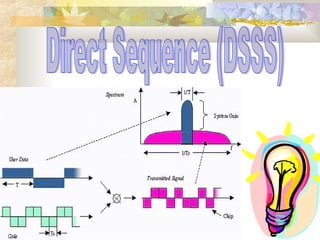
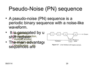
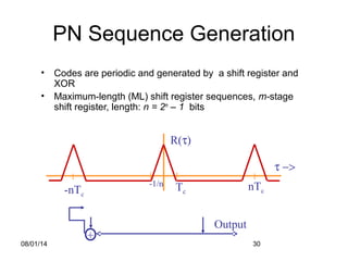
Generating PN Sequences
• Take m=2 =>L=3
• cn=[1,1,0,1,1,0, . . .],
usually written as
bipolar cn=[1,1,-1,1,1,-1,
. . .]
m Stages connected
to modulo-2 adder
2 1,2
3 1,3
4 1,4
5 1,4
6 1,6
8 1,5,6,7
+
Output
( )
−≤≤−
=
=
= ∑=
+
11/1
01
1
1
LmL
m
cc
L
mR
L
n
mnnc](https://image.slidesharecdn.com/dsssfinal-140731222131-phpapp01/85/Dsss-final-31-320.jpg)

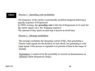
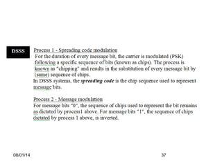
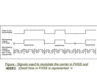
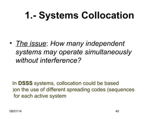


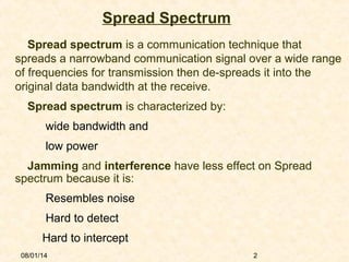
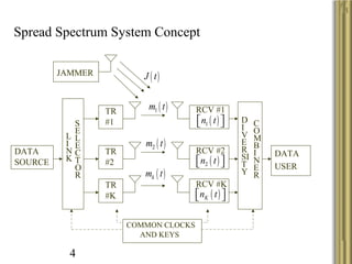
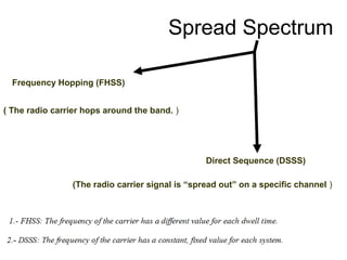
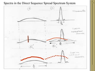
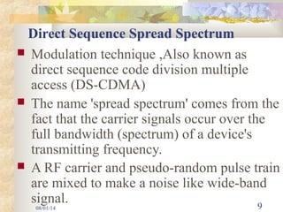
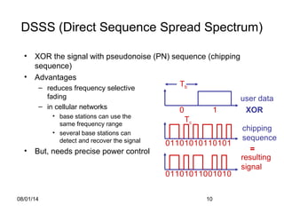
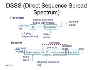
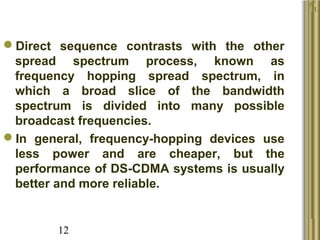
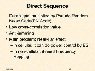
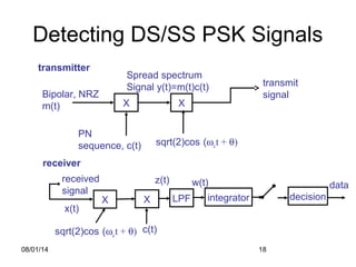
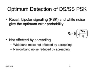
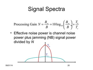
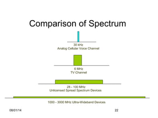
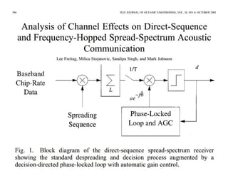
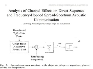
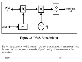
The document discusses spread spectrum communication techniques, specifically focusing on Direct Sequence Spread Spectrum (DSSS) and Frequency Hopping Spread Spectrum (FHSS). It explains their properties, advantages, differences, and applications, highlighting DSSS's ability to reduce noise and interference through the use of pseudo-noise sequences. The document also evaluates system performance aspects such as throughput, security, and the handling of multi-path environments.