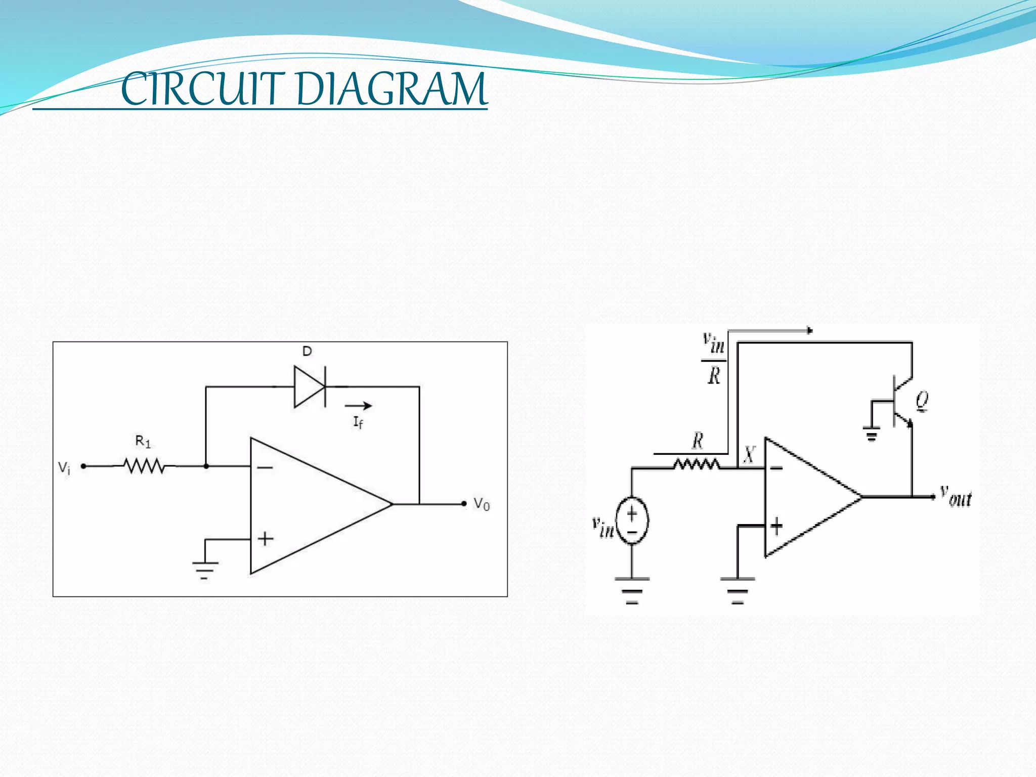
A PRESENTATION ON
LOGARITHMIC AMPLIFIERS
PRESENTEDBY;BIJOYDIPTAGHOSH
ELECTRICALENGINEERING
2ND YEAR(3RD SEM)
11101622011
INTRODUCTION
Logarithmic amplifiers, also known as log amps, are electronic
devices designed to convert an input signal's exponential relationship
into a linear output response. They are commonly used in various
applications, including signal processing, communication systems, and
measurement instruments. The primary function of logarithmic
amplifiers is to compress a wide dynamic range of input signal
amplitudes into a more manageable linear range at the output. This is
particularly useful when dealing with signals that span several orders of
magnitude, such as in Radio Frequency communication or audio
applications. By utilizing logarithmic amplifiers, it becomes easier to
accurately process and measure signals that vary widely in amplitude..
The logarithmic amplifiers' ability to convert exponential signals into
linear ones makes them valuable components in various electronic
systems, contributing to improved signal-to-noise ratio and overall
performance.
CONTENTS
TOPICS COVERED HERE:
WHAT IS LOGARITHMIC AMPLIFIER
APPLICATIONS OF LOGARITHMIC AMPLIFIERS
CIRCUIT DIAGRAM
TRANS DIODE CONFIGURATION (RELATION BETWEEN OUTPUT
VOLTAGE WITH THE INPUT VOLTAGE AND THE FIXED RESISTENCE)
 Conclusion
 references
WHAT IS LOGARITHMIC AMPLIFIER
A log amplifier is an amplifier for which the
output voltage V0 is k times the natural log of the
input voltage Vi, this can be expressed as:
V0=k log ((Vi/ Vr)) ,where Vr is the normalization
constant in volts and K is the scale factor.
The term log amp is generally used in
communication technology, refers to calculate log
of an input signal’s envelope. All logarithmic
amplifiers must therefore specify a signal range
over which they will “log”.
APPLICATIONS OF LOGARITHMIC AMPLIFIERS
Logarithmic Amplifiers can be used in many ways,such
as:
To perform mathamatical operations like
multiplication , division , exponentiation.
To calculate the db value of a given quantity
As a true RMS converter
CIRCUIT DIAGRAM
TRANS DIODE CONFIGURATION
According to the virtual short concept, the voltage at the inverting input terminal of an op-amp will be
equal to the voltage at its non-inverting input terminal. So, the voltage at the inverting input terminal
will be zero volts.
The nodal equation at the inverting input terminal’s node is −
(O-Vi)/R1 + If=O
If=Vi/R1---------->Equation 1
The following is the equation for current flowing through a diode, when it is in forward bias −
If=Is e^(Vf/nVt)-------->Equation 2
where,
 Is is the saturation current of the diode,
 Vf is the voltage drop across diode, when it is in forward bias,
 Vt is the diode’s thermal equivalent voltage.
The KVL equation around the feedback loop of the op amp will be −
O-Vf-Vo=O
 Vf=-V0
Substituting the value of Vf in Equation 2, we get −
If=Is e^(-V0/nVt)
(Vi/R1)=Is e^(-V0/nVt)
ln(Vi/R1Is)=-V0/nRt
V0=-nRtln(Vi/R1Is)
Hence,the output voltage Vo will be proportional to the natural logarithm of the input voltage Vi for a fixed
value of resistance R1. V0 has a negative sign, which indicates that there exists a 1800 phase
difference between the input and the output.
CONCLUSION
In summery ,Dc log amp ICs have evoled into small
,easy-to-use, cost effective circuits nicely suited for
certain analog designs. The logarithmic function
convinently compresses wide dynamic range signals
and linearizes sensors with(semi-) exponential
transfer functions.Calibration procedures can
enhance log-amp performance, but are not
necessery in all applications.
REFERENCES
WEBSITES VISITED:
www.wikipedia.com
www.powershow.com
BOOKS VISITED:
ELECTRONICS:ANALOG AND DIGITAL, BY NAGRATH, PHI, 2004
ELECTRONIC PRINCIPLES, BY MALVINO,6/e,tmh
Integrated electronics, by millman & halkies,tata mcgrow hill.
THANK YOU

logarithmic amplifiers.pptx

  • 1.
    A PRESENTATION ON LOGARITHMICAMPLIFIERS PRESENTEDBY;BIJOYDIPTAGHOSH ELECTRICALENGINEERING 2ND YEAR(3RD SEM) 11101622011
  • 2.
    INTRODUCTION Logarithmic amplifiers, alsoknown as log amps, are electronic devices designed to convert an input signal's exponential relationship into a linear output response. They are commonly used in various applications, including signal processing, communication systems, and measurement instruments. The primary function of logarithmic amplifiers is to compress a wide dynamic range of input signal amplitudes into a more manageable linear range at the output. This is particularly useful when dealing with signals that span several orders of magnitude, such as in Radio Frequency communication or audio applications. By utilizing logarithmic amplifiers, it becomes easier to accurately process and measure signals that vary widely in amplitude.. The logarithmic amplifiers' ability to convert exponential signals into linear ones makes them valuable components in various electronic systems, contributing to improved signal-to-noise ratio and overall performance.
  • 3.
    CONTENTS TOPICS COVERED HERE: WHATIS LOGARITHMIC AMPLIFIER APPLICATIONS OF LOGARITHMIC AMPLIFIERS CIRCUIT DIAGRAM TRANS DIODE CONFIGURATION (RELATION BETWEEN OUTPUT VOLTAGE WITH THE INPUT VOLTAGE AND THE FIXED RESISTENCE)  Conclusion  references
  • 4.
    WHAT IS LOGARITHMICAMPLIFIER A log amplifier is an amplifier for which the output voltage V0 is k times the natural log of the input voltage Vi, this can be expressed as: V0=k log ((Vi/ Vr)) ,where Vr is the normalization constant in volts and K is the scale factor. The term log amp is generally used in communication technology, refers to calculate log of an input signal’s envelope. All logarithmic amplifiers must therefore specify a signal range over which they will “log”.
  • 5.
    APPLICATIONS OF LOGARITHMICAMPLIFIERS Logarithmic Amplifiers can be used in many ways,such as: To perform mathamatical operations like multiplication , division , exponentiation. To calculate the db value of a given quantity As a true RMS converter
  • 6.
  • 7.
    TRANS DIODE CONFIGURATION Accordingto the virtual short concept, the voltage at the inverting input terminal of an op-amp will be equal to the voltage at its non-inverting input terminal. So, the voltage at the inverting input terminal will be zero volts. The nodal equation at the inverting input terminal’s node is − (O-Vi)/R1 + If=O If=Vi/R1---------->Equation 1 The following is the equation for current flowing through a diode, when it is in forward bias − If=Is e^(Vf/nVt)-------->Equation 2 where,  Is is the saturation current of the diode,  Vf is the voltage drop across diode, when it is in forward bias,  Vt is the diode’s thermal equivalent voltage. The KVL equation around the feedback loop of the op amp will be − O-Vf-Vo=O  Vf=-V0 Substituting the value of Vf in Equation 2, we get − If=Is e^(-V0/nVt) (Vi/R1)=Is e^(-V0/nVt) ln(Vi/R1Is)=-V0/nRt V0=-nRtln(Vi/R1Is) Hence,the output voltage Vo will be proportional to the natural logarithm of the input voltage Vi for a fixed value of resistance R1. V0 has a negative sign, which indicates that there exists a 1800 phase difference between the input and the output.
  • 8.
    CONCLUSION In summery ,Dclog amp ICs have evoled into small ,easy-to-use, cost effective circuits nicely suited for certain analog designs. The logarithmic function convinently compresses wide dynamic range signals and linearizes sensors with(semi-) exponential transfer functions.Calibration procedures can enhance log-amp performance, but are not necessery in all applications.
  • 9.
    REFERENCES WEBSITES VISITED: www.wikipedia.com www.powershow.com BOOKS VISITED: ELECTRONICS:ANALOGAND DIGITAL, BY NAGRATH, PHI, 2004 ELECTRONIC PRINCIPLES, BY MALVINO,6/e,tmh Integrated electronics, by millman & halkies,tata mcgrow hill.
  • 10.