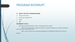
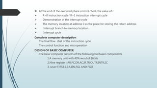
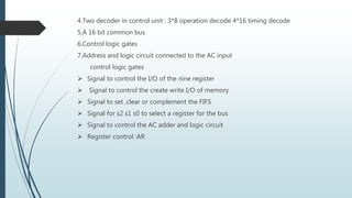
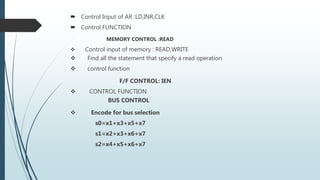
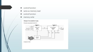
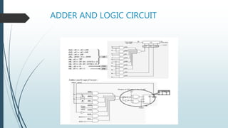
This document provides an overview of basic computer organization and design. It discusses memory reference instructions, input/output and interrupts, and the design of a basic computer. The computer consists of a memory unit, nine registers, flags, decoders, buses, and control logic. It describes the control functions for memory reading and writing, register selection, flag manipulation, and arithmetic operations using an adder and logic circuit. The document aims to provide a complete description of the basic components and design of a computer system.
Basic Computer Organization and Design
.....................................................................
The basic computer design represents all of the major concepts in CPU design without overwhelming students with the complexity of a modern commercial CPU.
COMPUTER INSTRUCTIONS & TIMING & CONTROL.
This is very useful to undarstand the topic COMPUTER INSTRUCTIONS & TIMING & CONTROL in computer system architecture.
To understand the basic concepts of 8085 microprocessor, microcontroller. The students will also learn about the programming methods and integration of peripherals to the micro-controller.
This is 2nd lecture of course on Microprocessor theory and Interfacing. This lecture discusses the Internal architecture of 8085 microprocessor in detail along with it's pin description.
Read| The latest issue of The Challenger is here! We are thrilled to announce that our school paper has qualified for the NATIONAL SCHOOLS PRESS CONFERENCE (NSPC) 2024. Thank you for your unwavering support and trust. Dive into the stories that made us stand out!
How to Make a Field invisible in Odoo 17Celine George
It is possible to hide or invisible some fields in odoo. Commonly using “invisible” attribute in the field definition to invisible the fields. This slide will show how to make a field invisible in odoo 17.
Welcome to TechSoup New Member Orientation and Q&A (May 2024).pdfTechSoup
In this webinar you will learn how your organization can access TechSoup's wide variety of product discount and donation programs. From hardware to software, we'll give you a tour of the tools available to help your nonprofit with productivity, collaboration, financial management, donor tracking, security, and more.
The French Revolution, which began in 1789, was a period of radical social and political upheaval in France. It marked the decline of absolute monarchies, the rise of secular and democratic republics, and the eventual rise of Napoleon Bonaparte. This revolutionary period is crucial in understanding the transition from feudalism to modernity in Europe.
For more information, visit-www.vavaclasses.com
Introduction to AI for Nonprofits with Tapp NetworkTechSoup
Dive into the world of AI! Experts Jon Hill and Tareq Monaur will guide you through AI's role in enhancing nonprofit websites and basic marketing strategies, making it easy to understand and apply.
Instructions for Submissions thorugh G- Classroom.pptxJheel Barad
This presentation provides a briefing on how to upload submissions and documents in Google Classroom. It was prepared as part of an orientation for new Sainik School in-service teacher trainees. As a training officer, my goal is to ensure that you are comfortable and proficient with this essential tool for managing assignments and fostering student engagement.
Macroeconomics- Movie Location
This will be used as part of your Personal Professional Portfolio once graded.
Objective:
Prepare a presentation or a paper using research, basic comparative analysis, data organization and application of economic information. You will make an informed assessment of an economic climate outside of the United States to accomplish an entertainment industry objective.
1. BASIC COMPUTER ORGANISATION AND DESIGN
Presented by,
R.RAMADEVI,
I-M.SC(CS&IT)
Nadar Saraswathi College Of Arts And Science, Theni.
2. BASIC COMPUTER ORGANIZATION AND
DESIGN
MEMORY REFERENCEIN INSTRUCTION
INPUT OUTPUT AND INTERRUPT COMPLETE COMPUTER DESCRIPTION
DESIGN OF A BASIC COMPUTER
DESIGN OF ACCUMULATOR LOGIC
3. MEMORY REFERENCE INSTRUCTIONS
D7:Register or I/O=1
D6-D0=7
Instruction:
AND TO AC
ADD TO AC
LDA : Memory read
STU : Memory write
BUN : branch unconditionally
BSA : branch and save return address
Return address : save return address(13521)
4. SUBROUTINE CALL
0 BSA L35
PC=20
PC=21 NEXT INSTRUCTION
135 21 (return address)
pc=136 subroutine
1 Bun 135
5. ISZ : increment and skip if zero control flow chart
flow chart for the 7mmemory reference instruction
the longest instruction : ISZ(76)
3 bit sequence counter
INPUT-OUTPUT ANT INTERRUPT
Input-output configuration:
Input register (INPR) output register(OUTR)
There two register communicate with a communication interface serially and with the AC in
parallel
Each quantity of information has eight bits of an alphanumeric code
Input flag(FGI),output flag(FGO)
FGI : set when INPR is ready clear when INPR is empty
FGO: set when operation is completed clear when output device is in the process of
printing
INPUT-OUTPUT INSTRUCTION
P=D7IT3,IR(I)=Bi IR(6-11),B6-B11=6 I/O Instruction
6. PROGRAM INTERRUPT
INPUT-OUTPUT TRANSFER MODE
Programmed I/O
Interrupt-initiated I/O
DMA
IOP
INTERRUPT CYCLE:
During the executed phare , IEN is checked by the control
IEN=0 the programmer does not want to use the interrupt so control continues
with the next instruction cycle
IEN=1 the control circuit checks the flags bit if (FGI/FGO) FLAG SET TO I,R F/F
Set to 1
7. At the end of the executed phare control check the value of r
R=0 instruction cycle *R=1 instruction interrupt cycle
Demonstration of the interrupt cycle
The memory location at address 0 as the place for storing the return address
Interrupt branch to memory location
Interrupt cycle
Complete computer description:
The final flow chat of the instruction cycle
The control function and microperation
DESIGN OF BASIC COMPUTER
The basic computer consists of the following hardware components
1.A memory unit with 40% word of 16bits
2.Nine register : AR,PC,DR,AC,IR,TR,OUTR,INTR,SC
3. sever F/FS:I,S,E,R,IEN,FGL AND FGO
8. 4.Two decoder in control unit : 3*8 operation decode 4*16 timing decode
5.A 16 bit common bus
6.Control logic gates
7.Address and logic circuit connected to the AC input
control logic gates
Signal to control the I/O of the nine register
Signal to control the create write I/O of memory
Signal to set ,clear or complement the FIFS
Signal for s2 s1 s0 to select a register for the bus
Signal to control the AC adder and logic circuit
Register control :AR
9. Control Input of AR :LD,INR,CLK
Control FUNCTION
MEMORY CONTROL :READ
Control input of memory : READ,WRITE
Find all the statement that specify a read operation
control function
F/F CONTROL: IEN
CONTROL FUNCTION
BUS CONTROL
Encode for bus selection
s0=x1+x3+x5+x7
s1=x2+x3+x6+x7
s2=x4+x5+x6+x7