Download to read offline
![8085 ASSEMBLY LANGUAGE PROGRAMMING
Prof. K. Adisesha, MSc., MTech(Ph.D), NET Page 7
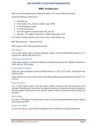
2) PROGRAM TO ADDITION TWO 8 BIT NUMBERS
INPUT : XX, YY
1) 20, 10
2) 2B, FA
OUTPUT
TRIAL Addition (XX+YY) Addition (XX+YY)
ADDRESS F001: F000 F001: F000
1 00 : 30 01 : 25
Sl no. ADDRESS HEX CODE LABEL MNEMONICS COMMENTS
1
2
3
4
5
6
7
8
9
10
8000
8002
8004
8005
8008
800B
800D
8010
8012
8015
3E, XX
06, YY
80
32,00,F0
D2,10,80
3E,01
C3,12,80
3E,00
32,01,F0
CF
Ahead 1
Ahead 2
MVI A, XX
MVI B, YY
ADD B
STA F000
JNC (Ahead 1)
MVIA, 01
JMP(Ahead 2)
MVIA, 00
STA F001
RST1
Move immediately to [A] the
data XX
Move immediately to [B] the
data YY
Add [B] with [A]
Store contents of [A] in specified
location
Jump on no carry to specified
location
Move immediately to [A] the
data(01)H
Jump unconditionally ahead
Move immediately to [A] the
data(00)H
Store contents of [A] in specified
location
Restart](https://image.slidesharecdn.com/8085alpprograms-201225163358/85/8085-alp-programs-7-320.jpg)
![8085 ASSEMBLY LANGUAGE PROGRAMMING
Prof. K. Adisesha, MSc., MTech(Ph.D), NET Page 8
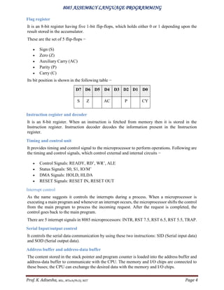
3) PROGRAM TO SUBTRACT TWO 8 BIT NUMBERS
INPUT : XX, YY
1) 20, 10
2) 2B, FA
OUTPUT
TRIAL Subtraction (XX-YY) Subtraction (XX-YY)
ADDRESS F001: F000 F001: F000
1 00 : 10 01 : 31
Sl no. ADDRESS HEX CODE LABEL MNEMONICS COMMENTS
1
2
3
4
5
6
7
8
9
10
8000
8002
8004
8005
8008
800B
800D
8010
8012
8015
3E, XX
06, YY
90
32,00,F0
D2,10,80
3E,01
C3,12,80
3E,00
32,01,F0
CF
Ahead 1
Ahead 2
MVI A, XX
MVI B, YY
SUB B
STA F000
JNC (Ahead 1)
MVIA, 01
JMP(Ahead 2)
MVIA, 00
STA F001
RST1
Move immediately to [A] the
data XX
Move immediately to [B] the
data YY
Subtract [B] with [A]
Store contents of [A] in specified
location
Jump on no carry to specified
location
Move immediately to [A] the
data(01)H
Jump unconditionally ahead
Move immediately to [A] the
data(00)H
Store contents of [A] in specified
location
Restart](https://image.slidesharecdn.com/8085alpprograms-201225163358/85/8085-alp-programs-8-320.jpg)
![8085 ASSEMBLY LANGUAGE PROGRAMMING
Prof. K. Adisesha, MSc., MTech(Ph.D), NET Page 9
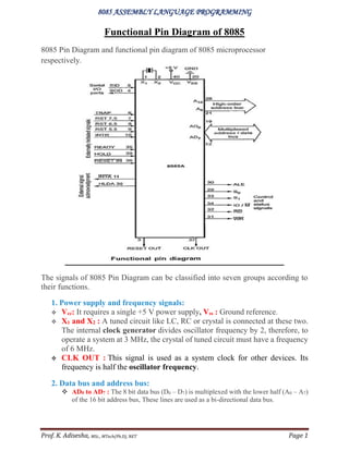
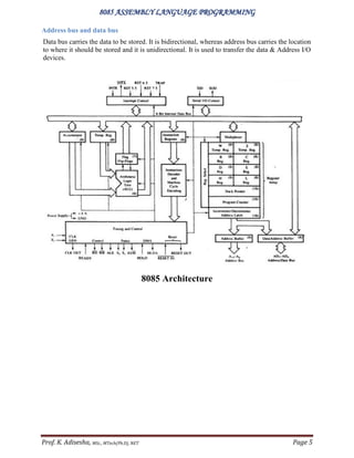
4) PROGRAM TO ADDITION TWO 16 BIT NUMBERS
F001: F000 (X) 4A : 2C
F101: F100 (Y) ED : 5B
F202:F201: F200 (X+Y) 01 : 37 : 87
Sl no. ADDRESS HEX CODE LABEL MNEMONICS COMMENTS
1
2
3
4
5
6
7
8
9
10
8000
8001
8004
8005
8008
8009
800C
800F
8010
8013
AF
2A, 00, F0
EB
2A,00,F1
19
22,00,F2
D2,10,80
3C
32,02,F2
CF
Ahead
XRA A
LHLD F000
XCHG
LHLD F100
DAD D
SHLD F200
JNC (Ahead)
INR A
STA F202
RST1
Clear accumulator and Flag
Load memory from specified
locations
Exchange contents of HL & DE
pairs
Load memory from specified
locations
Add HL & DE pairs
Store memory to specified
locations
Jump on no carry to ahead
address
Increment contents of
accumulator by one
Store contents of [A] in specified
location
Restart](https://image.slidesharecdn.com/8085alpprograms-201225163358/85/8085-alp-programs-9-320.jpg)
![8085 ASSEMBLY LANGUAGE PROGRAMMING
Prof. K. Adisesha, MSc., MTech(Ph.D), NET Page 10
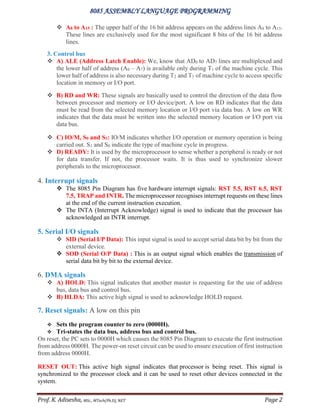
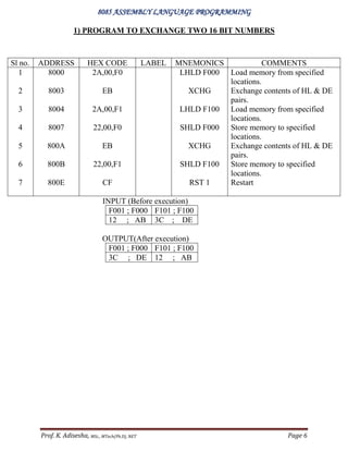
5) PROGRAM TO SUBTRACT TWO 16 BIT NUMBERS (X>Y)
Sl no. ADDRESS HEX CODE LABEL MNEMONICS COMMENTS
1
2
3
4
5
6
7
8
9
10
8000
8003
8004
8007
8008
8009
800C
800D
800E
8011
2A,00,F0
EB
2A,00,F1
7D
93
32,00,F2
7C
9A
32,01,F2
CF
LHLD F000
XCHG
LHLD F100
MOV A, L
SUB E
STA F200
MOV A, H
SBB D
STA F201
RST 1
Load memory from specified
locations
Exchange contents of HL & DE
pairs
Load memory from specified
locations
Move contents of [L] to [A]
Subtract [E] from [A]
Store result in specified location
Move contents of [H] to [A]
Subtract [D] from [A] with
borrow
Store result in specified location
Restart
F001: F000 (X) FA : 2C
F101: F100 (Y) BD : 5B
F202:F201: F200 (X-Y) 3C : D1](https://image.slidesharecdn.com/8085alpprograms-201225163358/85/8085-alp-programs-10-320.jpg)
![8085 ASSEMBLY LANGUAGE PROGRAMMING
Prof. K. Adisesha, MSc., MTech(Ph.D), NET Page 11
6) PROGRAM TO ADD TWO N BYTE NUMBERS
INPUT(X) F103 : F102 : F101 : F100 A4 : E6 : F3 : D7
INPUT(Y) F003 : F002 : F001 : F000 C3 : 54 : A2 : 1B
OUTPUT(X+Y) F204:F203 : F202 : F201 : F200 01: 68 : 3B: 95: F2
Sl no. ADDRESS HEX CODE LABEL MNEMONICS COMMENTS
1
2
3
4
5
6
7
8
9
10
11
12
13
14
15
16
17
18
19
20
21
8000
8003
8006
8009
800B
800E
800F
8010
8011
8012
8013
8014
8015
8018
8019
801C
801F
8021
8024
8026
8027
21,00,F0
01,00,F1
11,00,F2
3E,(NN)
32,00,81
AF
0A
8E
12
23
03
13
3A,00,81
3D
C2,0B,80
D2,24,80
3E,01
C3,26,80
3E,00
12
CF
LOOP
Ahead 1
Ahead 2
LXIH F000
LXIB F100
LXID F200
MVI A, (NN)
STA 8100
XRA A
LDAX B
ADC M
STAX D
INX H
INX B
INX D
LDA 8100
DCR A
JNZ (LOOP)
JNC (Ahead 1)
MVI A, 01
JMP (Ahead 2)
MVI A, 00
STAX D
RST 1
Load HL pair with specified data
Load BC pair with specified data
Load DE pair with specified data
Specify the number of bytes
Save the count
Clear accumulator and flags
Load [A] indirectly from address
specified by BC pair
Add memory to [A] with carry
Store contents of [A] indirectly in
location specified by DE pair
Update memory
Update BC register pair
Update DE register pair
Load [A] from specified location
Decrement count
Jump on no zero to perform loop
Jump on no carry to ahead address
Move immediately to [A] the
data(01)H
Jump unconditionally to ahead
address
Move immediately to [A] the
data(00)H
Store contents of [A] indirectly in
address specified by DE pair
Restart](https://image.slidesharecdn.com/8085alpprograms-201225163358/85/8085-alp-programs-11-320.jpg)
![8085 ASSEMBLY LANGUAGE PROGRAMMING
Prof. K. Adisesha, MSc., MTech(Ph.D), NET Page 12
7) PROGRAM FOR BLOCK TRANSFER
INPUT
8100:810:8102:8103:8104:8105:8106:8107:8108:8109:810A:810B:810C:810D:810E:810F
00 : 01: 02 : 03 : 04 : 05 : 06 : 07 : 08 : 09 : 0A : 0B : 0C : 0D : 0E : 0F
OUTPUT
8200:8201:8202:8203:8204:8205:8206:8207:8208:8209:820A:820B:820C:820D:820E:820F
00 : 01: 02 : 03 : 04 : 05 : 06 : 07 : 08 : 09 : 0A : 0B : 0C : 0D : 0E : 0F
Sl no. ADDRESS HEX CODE LABEL MNEMONICS COMMENTS
1
2
3
4
5
6
7
8
9
10
8000
8002
8005
8008
8009
800A
800B
800C
800D
8010
16,10
21,00,81
01,00,82
7E
02
23
03
15
C2,08,80
CF
LOOP
MVI D, (10)H
LXIH 8100
LXIB 8200
MOV A,M
STAX B
INX H
INX B
DCR D
JNZ (LOOP)
RST1
Set count in [D]
Load HL pair with specified
address
Load BC pair with specified
address
Move contents of memory to [A]
Store contents of [A] indirectly
to location specified by BC pair
Update memory
Update BC pair
Decrement count in [D]
Jump on no zero to perform the
loop
Restart](https://image.slidesharecdn.com/8085alpprograms-201225163358/85/8085-alp-programs-12-320.jpg)
![8085 ASSEMBLY LANGUAGE PROGRAMMING
Prof. K. Adisesha, MSc., MTech(Ph.D), NET Page 13
8) PROGRAM TO BLOCK TRANSFER IN REVERSE ORDER
INPUT
8100:810:8102:8103:8104:8105:8106:8107:8108:8109:810A:810B:810C:810D:810E:810F
00 : 01: 02 : 03 : 04 : 05 : 06 : 07 : 08 : 09 : 0A : 0B : 0C : 0D : 0E : 0F
OUTPUT
820F:820E:820D:820C:820B:820A:8209:8208:8207:8206:8205:8204:8203:8202:8201:8200
0F : 0E : 0D : 0C : 0B : 0A : 09 : 08 : 07 : 06 : 05 : 04 : 03 : 02 : 01 : 00
Sl no. ADDRESS HEX CODE LABEL MNEMONICS COMMENTS
1
2
3
4
5
6
7
8
9
10
8000
8002
8005
8008
8009
800A
800B
800C
800D
8010
16,10
21,00,81
01,0F,82
7E
02
23
0B
15
C2,08,80
CF
LOOP
MVI D, (10)H
LXIH 8100
LXIB 820F
MOV A,M
STAX B
INX H
DCX B
DCR D
JNZ (LOOP)
RST1
Set count in [D]
Load HL pair with specified
address
Load BC pair with specified
address
Move contents of memory to [A]
Store contents of [A] indirectly
to location specified by BC pair
Update memory
Decrement BC pair by one
Decrement count in [D]
Jump on no zero to perform the
loop
Restart](https://image.slidesharecdn.com/8085alpprograms-201225163358/85/8085-alp-programs-13-320.jpg)
![8085 ASSEMBLY LANGUAGE PROGRAMMING
Prof. K. Adisesha, MSc., MTech(Ph.D), NET Page 14
9) PROGRAM TO ADD N DECIMAL NUMBERS (N= 10)
INPUT OUTPUT
8100:810:8102:8103:8104:8105:8106:8107:8108:8109 F201 F200
00 : 01: 02 : 03 : 04 : 05 : 06 : 07 : 08 : 09 00 45
Sl no. ADDRESS HEX CODE LABEL MNEMONICS COMMENTS
1
2
3
4
5
6
7
8
9
10
11
12
13
14
15
8000
8001
8003
8005
8008
8009
800A
800D
800E
800F
8010
8013
8014
8015
8018
AF
0E,0A
16,00
21,00,81
86
27
D2,0E,80
14
23
0D
C2,08,80
6F
62
22,00,F2
CF
LOOP
Ahead
XRA A
MVI C, (0A)H
MVI D , 00
LXIH 8100
ADD M
DAA
JNC(Ahead)
INR D
INX H
DCR C
JNZ(LOOP)
MOV L,A
MOV H,D
SHLD F200
RST 1
Clear accumulator and flags
Set N count in [C]
Clear [D]
Load HL pair with specified data
Add memory to [A]
Decimal adjust accumulator
Jump on no carry to ahead
address
Increment [D] by one
Update memory
Decrement count
Jump on no zero to perform loop
Move [A] to [L]
Move [D] to [H]
Store contents of HL pair to
specified consecutive locations
Restart](https://image.slidesharecdn.com/8085alpprograms-201225163358/85/8085-alp-programs-14-320.jpg)
![8085 ASSEMBLY LANGUAGE PROGRAMMING
Prof. K. Adisesha, MSc., MTech(Ph.D), NET Page 15
10) PROGRAM FOR ADDITION OF HEXA-DECIMAL NUMBERS
UNTILL ‘FF’ IS ENCOUNTERED
OUTPUT: ‘00’ up to ‘FF’ is displayed in data field.
Slno. ADDRESS HEX CODE LABEL MNEMONICS COMMENTS
1
2
3
4
5
6
7
8
9
10
8000
8001
8004
8005
8008
800B
800E
800F
8010
8013
AF
32,F9,FF
F5
CD,D3,06
11,FF,FF
CD,BE,04
F1
3C
C2,01,80
76
LOOP
XRA A
STA FFF9
PUSH PSW
CALL(UPDDT)
LXID FFFF
CALL(DELAY)
POP PSW
INR A
JNZ (LOOP)
HLT
Clear accumulator and flags
Store contents of accumulator in
specified location
Push [A] and flags to stack
Call display subroutine for data
field
Implement a delay of 0.5 s using
monitor delay subroutine
Pop[A] and flags off stack
Increment contents of [A] by one
Perform the loop until [A]
becomes zero
Halt](https://image.slidesharecdn.com/8085alpprograms-201225163358/85/8085-alp-programs-15-320.jpg)
![8085 ASSEMBLY LANGUAGE PROGRAMMING
Prof. K. Adisesha, MSc., MTech(Ph.D), NET Page 16
11) PROGRAM FOR FOUR DIGIT BCD ADDITION
INPUT(X) F101 : F100 57 : 93
INPUT(Y) F001 : F000 64 : 21
OUTPUT(X+Y) F202 : F201 : F200 01: 22 : 14
Slno ADDRESS HEX CODE LABEL MNEMONICS COMMENTS
1
2
3
4
5
6
7
8
9
10
11
12
13
14
15
16
17
18
19
20
21
8000
8003
8006
8009
800B
800E
800F
8010
8011
8012
8013
8014
8015
8018
8019
801C
801F
8021
8024
8026
8027
21,00,F0
01,00,F1
11,00,F2
3E,02
32,00,81
0A
8E
27
12
23
03
13
3A,00,81
3D
C2,0B,80
D2,24,80
3E,01
C3,26,80
3E,00
12
CF
LOOP
Ahead 1
Ahead 2
LXIH F000
LXIB F100
LXID F200
MVI A, (02)
STA 8100
LDAX B
ADC M
DAA
STAX D
INX H
INX B
INX D
LDA 8100
DCR A
JNZ (LOOP)
JNC (Ahead 1)
MVI A, 01
JMP (Ahead 2)
MVI A, 00
STAX D
RST 1
Load HL pair with specified data
Load BC pair with specified data
Load DE pair with specified data
Specify the number of bytes
Save the count
Load [A] indirectly from address
specified by BC pair
Add memory to [A] with carry
Decimal adjust accumulator
Store contents of [A] indirectly in
location specified by DE pair
Update memory
Update BC register pair
Update DE register pair
Load [A] from specified location
Decrement count
Jump on no zero to perform loop
Jump on no carry to ahead address
Move immediately to [A] the data(01)H
Jump unconditionally to ahead address
Move immediately to [A] the data(00)H
Store contents of [A] indirectly in
address specified by DE pair
Restart](https://image.slidesharecdn.com/8085alpprograms-201225163358/85/8085-alp-programs-16-320.jpg)
![8085 ASSEMBLY LANGUAGE PROGRAMMING
Prof. K. Adisesha, MSc., MTech(Ph.D), NET Page 17
12) PROGRAM TO FIND 2`S COMPLEMENT OF 8 BIT/ 16 BIT
NUMBER
DATA INPUT OUTPUT(2`s complement)
8-Bit F000 : 7A F100 : 87
16-Bit F001 : F000 :: 1A: 26 F101 : F100 :: E5: DA
Slno ADDRESS HEX CODE LABEL MNEMONICS COMMENTS
1
2
3
4
5
6
7
8
9
10
11
12
13
14
8000
8002
8005
8008
8009
800A
800B
800C
800F
8010
8013
8016
8017
801A
06,01/(02)
11,01,00
21,00,F0
7E
2F
77
05
CA, 13,80
23
C3,08,80
2A,00,F0
19
22,00,F1
CF
LOOP
Ahead
MVI B,01/(02)
LXID 0001
LXIH F000
MOV A,M
CMA
MOV M,A
DCR B
JZ (Ahead)
INX H
JMP(Loop)
LHLD F000
DAD D
SHLD F100
RST 1
Move to [B] (01) for 8-bit & (02)
for 16-bit complement of data
Load DE pair with specified data
Load HL pair with specified data
Copy contents of memory to [A]
Complement contents of [A]
Copy contents of [A] to memory
Decrement [B] by one
Jump on zero to ahead address
Update memory
Jump unconditionally to perform
loop
Load contents of HL pair from
specified locations
Add HL and DE pair of registers
Store contents of HL pair to
specified locations
Restart](https://image.slidesharecdn.com/8085alpprograms-201225163358/85/8085-alp-programs-17-320.jpg)
![8085 ASSEMBLY LANGUAGE PROGRAMMING
Prof. K. Adisesha, MSc., MTech(Ph.D), NET Page 18
13) PROGRAM FOR BLOCK EXCHANGE
INPUT
F000:F001:F002:F003:F004:F005:F006:F007:F008:F009:F00A:F00B:F00C:F00D:F00E:F00F
00 : 01 : 02 : 03 : 04 : 05 : 06 : 07 : 08 : 09 : 0A : 0B : 0C : 0D : 0E : 0F
F100:F101:F102:F103:F104:F105:F106:F107:F108:F109:F10A:F10B:F10C:F10D:F10E:F10F
10 : 11 : 12 : 13 : 14 : 15 : 16 : 17 : 18 : 19 : 1A : 1B : 1C : 1D : 1E : 1F
F000:F001:F002:F003:F004:F005:F006:F007:F008:F009:F00A:F00B:F00C:F00D:F00E:F00F
10 : 11 : 12 : 13 : 14 : 15 : 16 : 17 : 18 : 19 : 1A : 1B : 1C : 1D : 1E : 1F
F100:F101:F102:F103:F104:F105:F106:F107:F108:F109:F10A:F10B:F10C:F10D:F10E:F10F
00 : 01 : 02 : 03 : 04 : 05 : 06 : 07 : 08 : 09 : 0A : 0B : 0C : 0D : 0E : 0F
OUTPUT
Sl no. ADDRESS HEX CODE LABEL MNEMONICS COMMENTS
1
2
3
4
5
6
7
8
9
10
11
12
13
8000
8003
8006
8008
8009
800A
800B
800C
800D
800E
800F
8010
8013
21,00,F0
11,00,F1
0E,10
1A
46
77
78
12
23
13
0D
C2,08,80
CF
LOOP
LXIH F000
LXID F100
MVI C,(10)H
LDAX D
MOV B,M
MOV M,A
MOV A,B
STAX D
INX H
INX D
DCR C
JNZ(Loop)
RST 1
Load HL pair with specified
address
Load HL pair with specified
address
Set counter in [C] for N counts
Load [A] indirectly from address
indicated by DE pair
Copy contents of memory to[B]
Copy contents of [A] to memory
Copy contents of [B] to [A]
Store contents of [A] indirectly
onto address in DE pair
Update memory
Update DE register pair
Decrement [C] by 1
Perform the loop until [C]
becomes zero
Restart](https://image.slidesharecdn.com/8085alpprograms-201225163358/85/8085-alp-programs-18-320.jpg)
![8085 ASSEMBLY LANGUAGE PROGRAMMING
Prof. K. Adisesha, MSc., MTech(Ph.D), NET Page 19
14) PROGRAM FOR SORTING AN ARRAY OF ‘N-NUMBERS’ IN ASCENDING
ORDER
INPUT F100:F101:F102:F103:F104:F105:F106:F107:F108:F109
01 : 02 : 03 : 04 : 05 : 06 : 07 : 08 : 09 : 0A
OUTPUT F100:F101:F102:F103:F104:F105:F106:F107:F108:F109
0A : 01 : 09 : 05 : 03 : 06 : 08 : 07 : 04 : 02
Sl no. ADDRESS HEX CODE LABEL MNEMONICS COMMENTS
1
2
3
4
5
6
7
8
9
10
11
12
13
14
15
16
17
18
19
8000
8001
8003
8004
8005
8008
8009
800A
800B
800E
800F
8010
8011
8012
8013
8014
8017
8018
801B
AF
06,0B
48
0D
21,00,F1
7E
23
BE
DA,13,80
56
77
2B
72
23
0D
C2,08,80
05
C2,03,80
CF
START
LOOP
AHEAD
XRA A
MVI B,0B
MOV C,B
DCR C
LXIH F100
MOV A,M
INX H
CMP M
JC (AHEAD)
MOV D,M
MOV M,A
DCX H
MOV M,D
INX H
DCR C
JNZ (LOOP)
DCR B
JNZ (START)
RST 1
Clear accumulator & flags
Move a count (N+1) in [B]
Copy contents of [B] to [C]
Decrement contents of [C] by one
Load the specified address in HL pair
Copy contents of [M] to [A]
Update memory
Compare memory with accumulator
Jump on carry to ahead address
Copy contents of [M] to [D]
Copy contents of [A] to [M]
Decrement HL pair by one
Copy contents of [D] to [M]
Increment contents of HL pair by one
Decrement contents of [C] by one
Jump on no zero to perform the loop
Decrement count in [B]
Jump on no zero to specified address
Restart](https://image.slidesharecdn.com/8085alpprograms-201225163358/85/8085-alp-programs-19-320.jpg)
![8085 ASSEMBLY LANGUAGE PROGRAMMING
Prof. K. Adisesha, MSc., MTech(Ph.D), NET Page 20
15) PROGRAM TO CHECK 2-OUT-OF-5 CODE
Sl no. ADDRESS HEX CODE LABEL MNEMONICS COMMENTS
1
2
3
4
5
6
7
8
9
10
11
12
13
14
15
16
17
18
19
8000
8003
8005
8007
8009
800C
800F
8010
8013
8014
80015
8018
8019
801B
801E
8020
8023
8025
8028
3A,00,F0
0E,05
16,00
E6,E0
C2,23,80
3A,00,F0
0F
D2,14,80
14
0D
C2,0F,80
7A
FE,02
C2,23,80
3E,FF
C2,25,80
3E,00
32,00,F1
CF
LOOP
AHEAD 2
AHEAD 1
AHEAD 3
LDA F000
MVI C,05
MVI D,00
ANI E0
JNZ (AHEAD 1)
LDA F000
RRC
JNC(AHEAD 2)
INR D
DCR C
JNZ(LOOP)
MOV A,D
CPI ,02
JNZ(AHEAD 1)
MVI A, FF
JMP(AHEAD 3)
MVI A, 00
STA F100
RST 1
Load data into accumulator from
specified location
Move a count (05)H in [C]
Clear contents of [D]
Logical AND (E0) H with [A]
Jump on no zero to specified address
Load data into accumulator from
specified location
Rotate contents of [A] to right
Jump on no carry to ahead address
Increment count in [D]
Decrement contents of [C] by one
Jump on no zero to perform the loop
Copy contents of [D] to [A]
Compare (02) H immediately with [A]
Jump on no zero to specified address
Move ‘FF’ to [A] immediately
Jump to specified location
unconditionally
Move ‘00’ to [A] immediately
Store data from accumulator into
specified location
Restart
INPUT OUTPUT
F000: 11 F100: FF
F000: 13 F100: 00](https://image.slidesharecdn.com/8085alpprograms-201225163358/85/8085-alp-programs-20-320.jpg)
![8085 ASSEMBLY LANGUAGE PROGRAMMING
Prof. K. Adisesha, MSc., MTech(Ph.D), NET Page 21
16) PROGRAM TO MULTIPLY TWO DIGIT BCD
INPUT OUTPUT
F001: F000 F101: F100
11 : 12 01 : 32
Sl no. ADDRESS HEX CODE LABEL MNEMONICS COMMENTS
1
2
3
4
5
6
7
8
9
10
11
12
13
14
15
16
17
18
19
20
8000
8003
8006
8007
800A
800B
800C
800D
800E
800F
80011
8012
8013
8014
8015
8017
8018
8019
801C
801F
21,00,00
3A,00,F0
47
3A,01,F0
4F
79
85
27
6F
3E,00
8C
27
67
78
C6,99
27
47
C2,0B,80
22,00,F1
CF
START
LXIH (0000 )H
LDA F000
MOV B,A
LDA F001
MOV C,A
MOV A,C
ADD L
DAA
MOV L,A
MVI A,00
ADC H
DAA
MOV H,A
MOV A,B
ADI ,99
DAA
MOV B,A
JNZ(START)
SHLD(F100)
RST 1
Move a count (0000)H in HL pair
Load data into accumulator from
specified location
Copy contents of [A] to [B]
Load data into accumulator from
specified location
Copy contents of [A] to [C]
Copy contents of [C] to [A]
Add [L] to accumulator
Decimal adjust [A]
Copy contents of [A] to [L]
Clear contents of [A]
Add contents of [H] to [A]
Decimal adjust [A]
Copy contents of [A] to [H]
Copy contents of [B] to [A]
Add immediately to accumulator 99
Decimal adjust [A]
Copy contents of [A] to [B]
Jump on no zero to specified
address
Store data from HL pair onto
specified location
Restart](https://image.slidesharecdn.com/8085alpprograms-201225163358/85/8085-alp-programs-21-320.jpg)

The document describes the 8085 microprocessor, including its pin diagram, functional units, architecture, and example assembly language programs. Specifically, it provides details on the 8085's power supply and frequency pins, data and address buses, control signals, interrupt signals, and serial and DMA signals. It outlines the 8085's functional units like the accumulator, arithmetic logic unit, registers, and timing and control unit. Example programs are provided to exchange 16-bit numbers, add and subtract 8-bit and 16-bit numbers, and add two N-byte numbers.