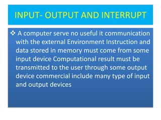
The document discusses input-output devices and interrupt handling in a computer system. It describes:
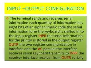
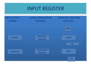
1) How input from devices like keyboards is received through an input register and output to devices like printers is sent through an output register.
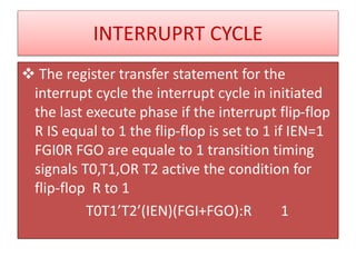
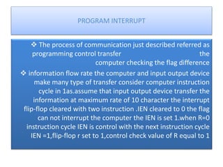
2) How interrupt handling works, with an interrupt flip-flop getting set when input or output flags are raised, causing the computer to save its return address and branch to an interrupt service program.
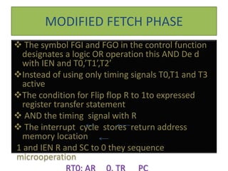
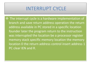
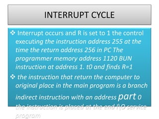
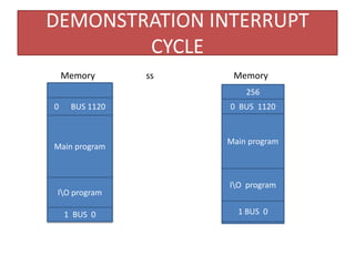
3) The interrupt cycle in more detail, explaining how the return address is stored and how the computer returns to the main program after servicing the interrupt.
![INPUT –OUTPUT INSTRUCTION
D7IT3=P(common to all input-output instruction)
IR(i)=B[bit in IR(6-11)that specifies the instruction]
P: clear sc
INP PB11: SC 0 input character
OUT PB10: AC(0-7) INPR,FGI 0 output character
SKI PB9: OUTR AC(0-7),FGO 0 skip on input flag
SKO PB8: IF(FGI=1)Then(PC PC+1) skip on output flag
ION PB7: IF(FGI=1)Then(PC PC+1) interrupt enable on
IOF PB6: IEN 1 interrupt enable off](https://image.slidesharecdn.com/dp-181003125835/85/input-8-320.jpg)
![FLOWCHART
= 0 = 1 interrupt cycle
R
O
E
Store return address
in location 0
M [0] PC
Fetch & decode
instruction
Branch to location
1 pc 1
IEN 0
R 0
Execute
instruction G](https://image.slidesharecdn.com/dp-181003125835/85/input-13-320.jpg)