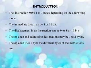
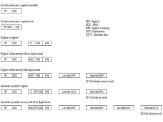
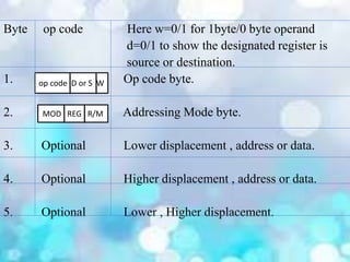
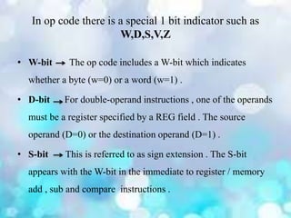
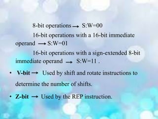
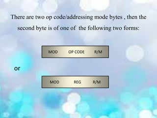
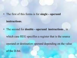
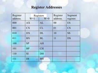
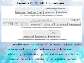
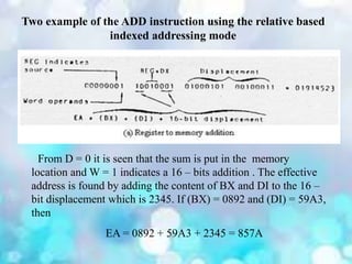
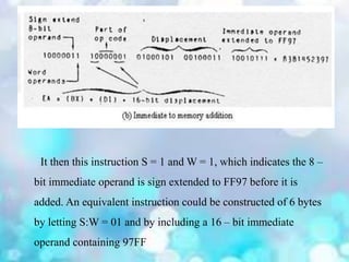
2. INTRODUCTION
• The instruction 8086 1 to 7 bytes depending on the addressing
mode.
• The immediate byte may be 8 or 16 bit.
• The displacement in an instruction can be 0 or 8 or 16 bits.
• The op code and addressing designations may be 1 to 2 bytes.
• The op code uses 2 byte the different bytes of the instructions
are
3.
4. Byte op code Here w=0/1 for 1byte/0 byte operand
d=0/1 to show the designated register is
source or destination.
1. Op code byte.
2. Addressing Mode byte.
3. Optional Lower displacement , address or data.
4. Optional Higher displacement , address or data.
5. Optional Lower , Higher displacement.
op code D or S W
MOD REG R/M
5. In op code there is a special 1 bit indicator such as
W,D,S,V,Z
• W-bit The op code includes a W-bit which indicates
whether a byte (w=0) or a word (w=1) .
• D-bit For double-operand instructions , one of the operands
must be a register specified by a REG field . The source
operand (D=0) or the destination operand (D=1) .
• S-bit This is referred to as sign extension . The S-bit
appears with the W-bit in the immediate to register / memory
add , sub and compare instructions .
6. 8-bit operations S:W=00
16-bit operations with a 16-bit immediate
operand S:W=01
16-bit operations with a sign-extended 8-bit
immediate operand S:W=11 .
• V-bit Used by shift and rotate instructions to
determine the number of shifts.
• Z-bit Used by the REP instruction.
7. There are two op code/addressing mode bytes , then the
second byte is of one of the following two forms:
or
MOD OP CODE R/M
MOD REG R/M
8. • The first of this forms is for single - operand
instructions.
• The second for double - operand instructions , in
which case REG specifies a register that is the source
operand or destination operand depending on the value
of the D-bit.
9. Register Addresses
Register
address. W=1 W=0
Register
address.
Segment
register.
000 AX AL 00 ES
001 CX CL 01 CS
010 DX DL 10 SS
011 BX BL 11 DS
100 SP AH
101 BP CH
110 SI DH
111 DI BH
Registers
10. Address Mode and default segment Registers for Various
MOD and R/M field combinations
11. • If MOD , an effective address is computed according to the
entire in the table.
• If MOD = 00 means that there is no displacement except when
R/M = 110.
• If MOD = 01 means that the third byte of the instruction
contains an 8 - bit displacement which is automatically sign -
extended to 16 – bits.
• If MOD = 10 means that the third and fourth bytes of the
instructions contain a 16 – displacement.
• If MOD = 11, the operand is in the register whose address is
designated by the R/M field.
12. Formats for the ADD instructions
An ADD causes the contents of the location indicated by the
source operand to be added to the contents of the location
indicated by the destination operand and the sum to replace the
contents of the location indicated by the destination operand .
13. Two equivalent instructions for adding the content of the BH
registers to those of the CL register.
• In the first instruction D = 1 indicates that REG = 001 = CL is
where the sum will be stored . MOD = 11, so that R/M
designates a register, the register 111 = BH.
• In the second instruction, D = 0, which causes REG = 111
=BH to be the source . Again MOD = 11 and R/M designates a
register, which in this case is 001 = CL.
14. Two example of the ADD instruction using the relative based
indexed addressing mode
From D = 0 it is seen that the sum is put in the memory
location and W = 1 indicates a 16 – bits addition . The effective
address is found by adding the content of BX and DI to the 16 –
bit displacement which is 2345. If (BX) = 0892 and (DI) = 59A3,
then
EA = 0892 + 59A3 + 2345 = 857A
15. It then this instruction S = 1 and W = 1, which indicates the 8 –
bit immediate operand is sign extended to FF97 before it is
added. An equivalent instruction could be constructed of 6 bytes
by letting S:W = 01 and by including a 16 – bit immediate
operand containing 97FF