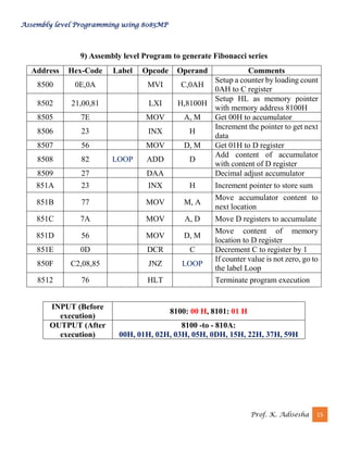
The document describes an assembly level program for the 8085 microprocessor that converts a hexadecimal number to binary coded decimal (BCD). It uses an iterative loop to process each hexadecimal digit stored in memory location 8000H. Each digit is added to the accumulator, decimal adjusted using DAA instruction, and stored in BCD at memory locations 8001H and 8002H if there is a carry. The program clears flags, decrements the loop counter, and continues until all digits are converted.
![Assembly level Programming using 8085MP
Prof. K. Adisesha 11
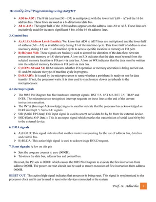
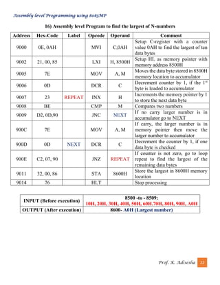
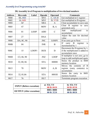
5) PROGRAM TO SUBTRACT TWO 16 BIT NUMBERS (X>Y)
Address Hex-code Label Opcode Operand Comments
8000 2A, 00, F0 LHLD F000
Load memory from specified
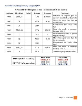
locations.
8003 EB XCHG
Exchange contents of HL &
DE pairs.
8004 2A, 00, F1 LHLD F100
Load memory from specified
locations.
8007 7D MOV A, L Move content of [L] to [A]
8008 93 SUB E Subtract [E] from [A]
8009 32, 00, F2 STA F200
Store memory to specified
locations.
800C 7C MOV A, H Move content of [H] to [A]
800D 9A SBB D
Subtract with borrow [D] from
[A]
800E 32,01, F2 STA F201
Store memory to specified
locations.
8011 76 HLT Halt
INPUT (Before
execution)
F001: F000 (X)
FA : 2C
F101: F100
(Y)
BD : 5B
OUTPUT (After
execution)
F201: F200 (X-Y) 3C : D1](https://image.slidesharecdn.com/8085labprograms-230201192438-452a0fbd/85/8085_LAB_PROGRAMS-pdf-11-320.jpg)


![Database System Concepts AND architecture [Autosaved].pptx](https://cdn.slidesharecdn.com/ss_thumbnails/databasesystemconceptsandarchitectureautosaved-230817173311-be7f8590-thumbnail.jpg?width=640&height=640&fit=bounds)