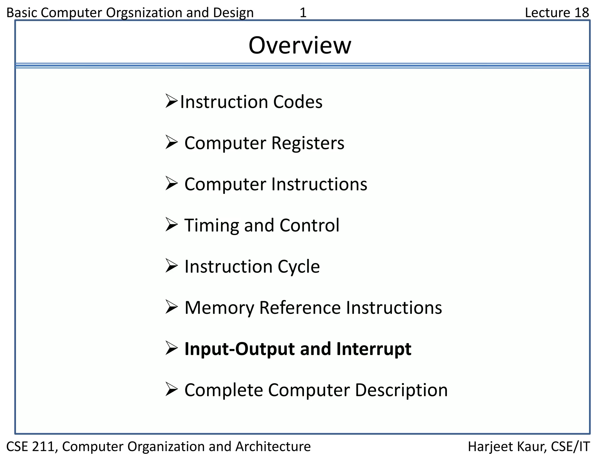
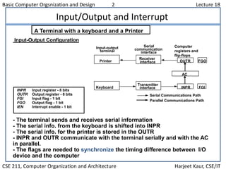
This document discusses input/output and interrupt handling in a basic computer system. It describes the I/O configuration including input and output registers and flags. It explains programmed and interrupt-initiated I/O, with the interrupt cycle storing the return address and branching to an interrupt service routine before returning to the main program. Input/output and interrupt instructions are also outlined.
![Basic Computer Orgsnization and Design 7 Lecture 18
CSE 211, Computer Organization and Architecture Harjeet Kaur, CSE/IT
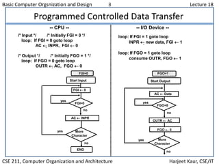
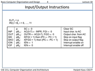
Flow Chart of Interrupt Cycle
R = Interrupt f/f
- The interrupt cycle is a HW implementation of a branch and save return address
operation.
- At the beginning of the next instruction cycle, the instruction that is read from
memory is in address 1.
- At memory address 1, the programmer must store a branch instruction that sends
the control to an interrupt service routine
- The instruction that returns the control to the original program is "indirect BUN 0"
Store return address
R
=1=0
in location 0
M[0] PC
Branch to location 1
PC 1
IEN 0
R 0
Interrupt cycleInstruction cycle
Fetch and decode
instructions
IEN
FGI
FGO
Execute
instructions
R 1
=1
=1
=1
=0
=0
=0](https://image.slidesharecdn.com/lecture18-130904040443-/85/Lecture-18-7-320.jpg)
![Basic Computer Orgsnization and Design 8 Lecture 18
CSE 211, Computer Organization and Architecture Harjeet Kaur, CSE/IT
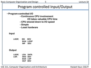
Register Transfer Operations in Interrupt Cycle
Register Transfer Statements for Interrupt Cycle
- R F/F 1 if IEN (FGI + FGO)T0T1T2
T0T1T2 (IEN)(FGI + FGO): R 1
- The fetch and decode phases of the instruction cycle
must be modified Replace T0, T1, T2 with R'T0, R'T1, R'T2
- The interrupt cycle :
RT0: AR 0, TR PC
RT1: M[AR] TR, PC 0
RT2: PC PC + 1, IEN 0, R 0, SC 0
After interrupt cycle
0 BUN 1120
0
1
PC = 256
255
1 BUN 0
Before interrupt
Main
Program
1120
I/O
Program
0 BUN 1120
0
PC = 1
256
255
1 BUN 0
Memory
Main
Program
1120
I/O
Program
256](https://image.slidesharecdn.com/lecture18-130904040443-/85/Lecture-18-8-320.jpg)