Downloaded 18 times
![Design Of Ota-C Filter For Biomedical Applications
www.iosrjournals.org 11 | Page
III. Conclusion
In this paper, we present “Design of OTA-C Filter for Biomedical Applications”. This method of
building block in SYNOPSYS Hspice tool. By the implementation of a low pass filter with a generic 0.18um
CMOS technology, some significant issues of the intrinsic properties of a real OTA, such as noise reduction and
finite gain. The proposed block and their application have been confirmed using Hspice simulation.
References
[1] Razavi, Behzad “Design of analog CMOS Integrated Circuits.”
[2] R.Jacob Baker, Harry W.Li and David E.Boyce, “CMOS Circuit Design, Layout andSimulation.”
[3] Mohamed O. Shaker , Sollman A. Mahmoud, Ahmed A. Sollman, “A CMOS Fifth-Order Low -Pass Current- Mode Filter Using a
Linear Transconductor.”
[4] KimmoLasanen, “Integrated analogue cmos circuits and structures for heart rate detectors and others low-voltage, low power
applications.”
[5] S. Koziel and S. Szczepanski, “Designof highly linear tunable CMOS-OTA for continuous-time filters.”
[6] “Star-HSPICE User’s Manual,” Avanti! Corp..Fremont. CA. Jun.2002, Release 2002.2.
[7] K.R. Laker and W.M.C. Sansen, Design of Analog Integrated Circuits and Systems. New York: McGraw-Hill. 1994](https://image.slidesharecdn.com/b0640711-150319044526-conversion-gate01/85/Design-of-Ota-C-Filter-for-Biomedical-Applications-5-320.jpg)

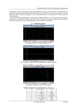
This document describes the design of an OTA-C filter for biomedical applications such as ECG signals. A fifth-order low pass Chebyshev filter with a cutoff frequency of 300Hz and power dissipation of 779nW was designed using a 0.18um CMOS process. Simulation results showed a gain of 22.5dB and CMRR of 93dB. The fully differential OTA-C filter provides higher common mode rejection and dynamic range compared to single-ended designs, while operating transistors in the sub-threshold region reduces power consumption. The proposed filter is suitable for low power portable biomedical applications.


