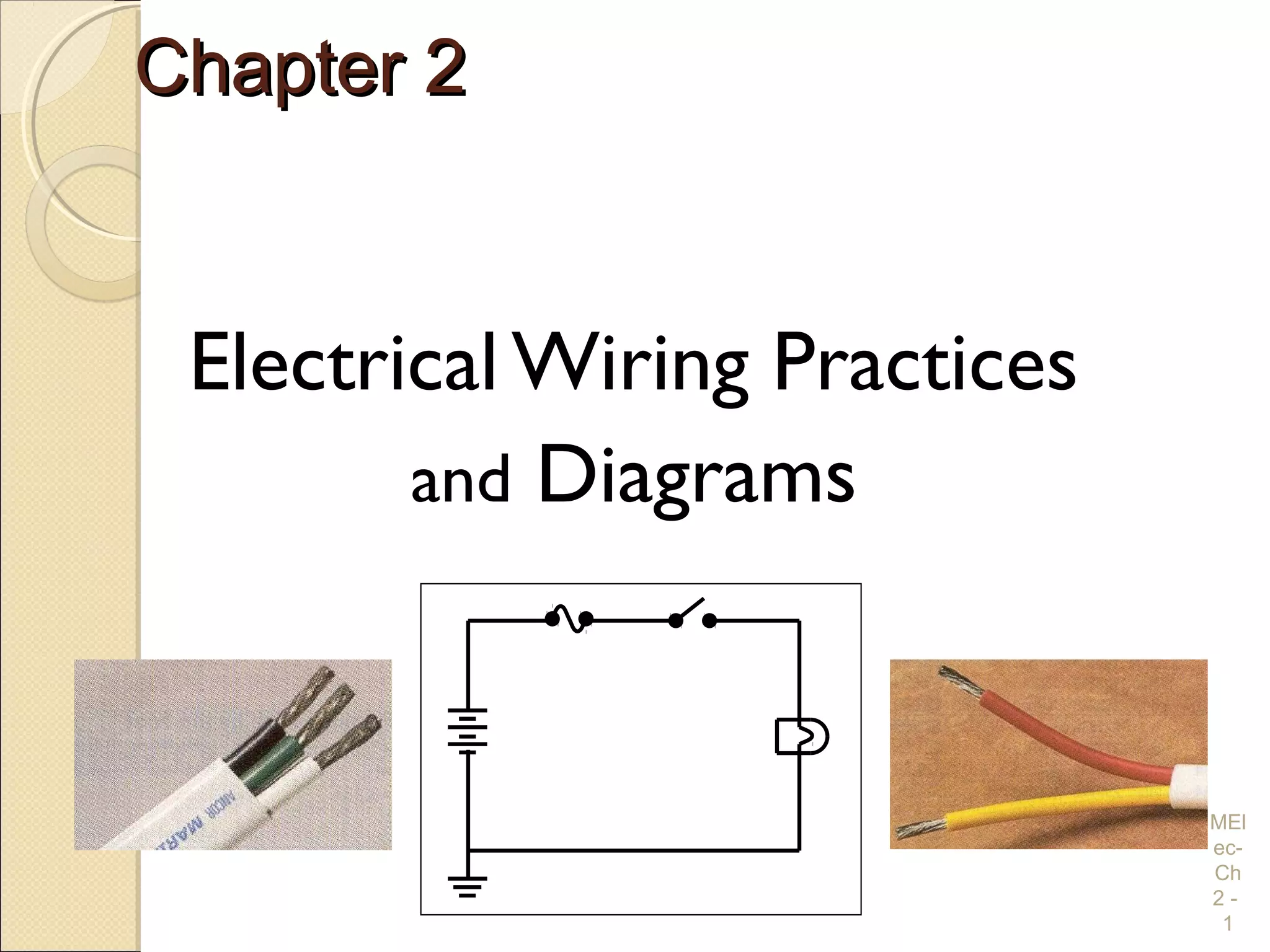
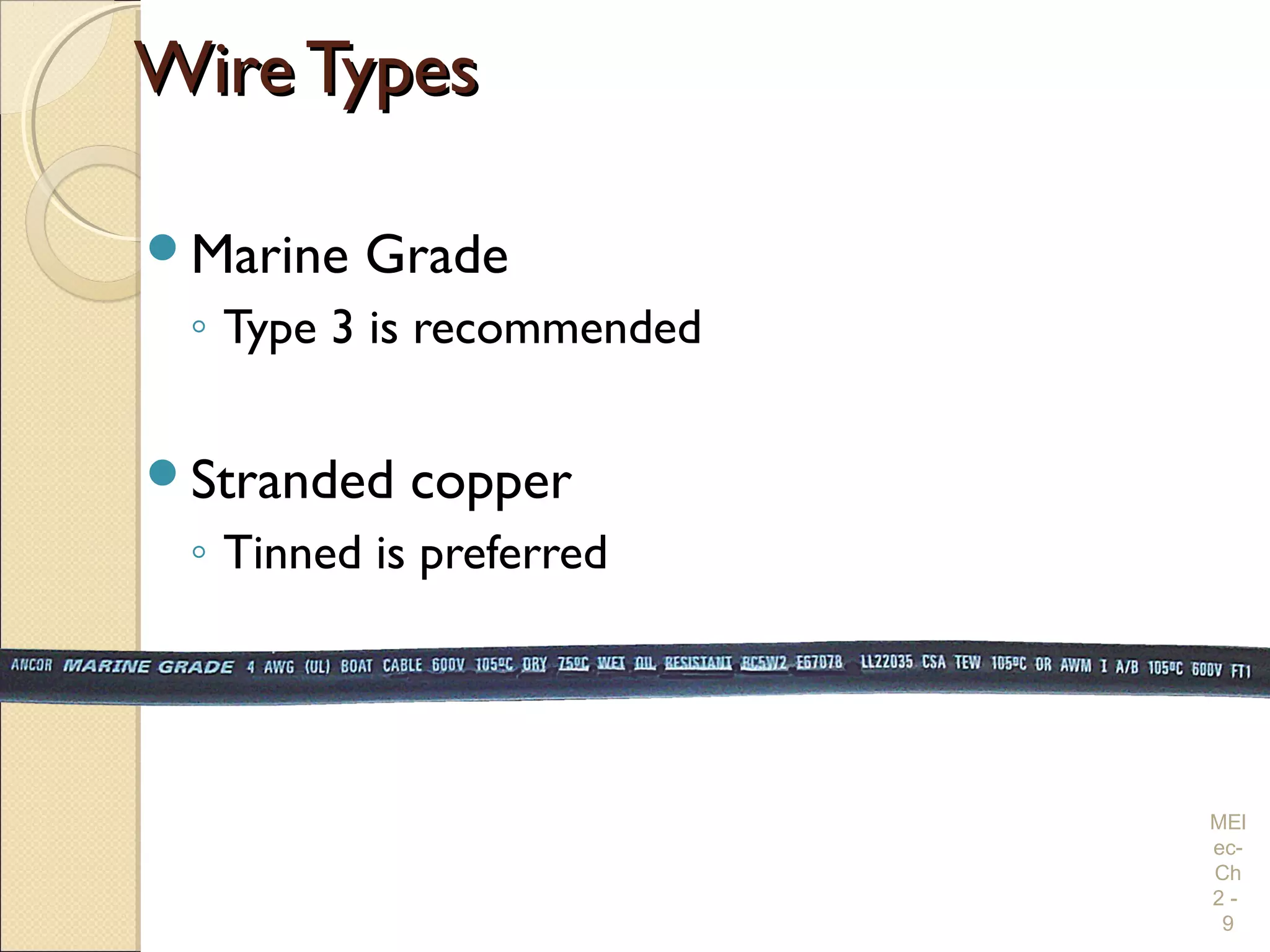
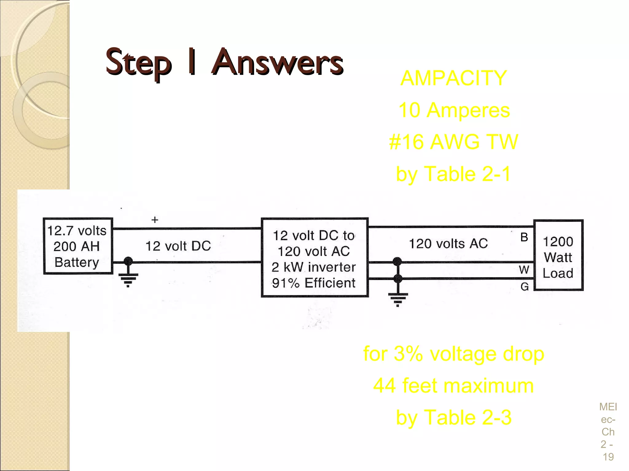
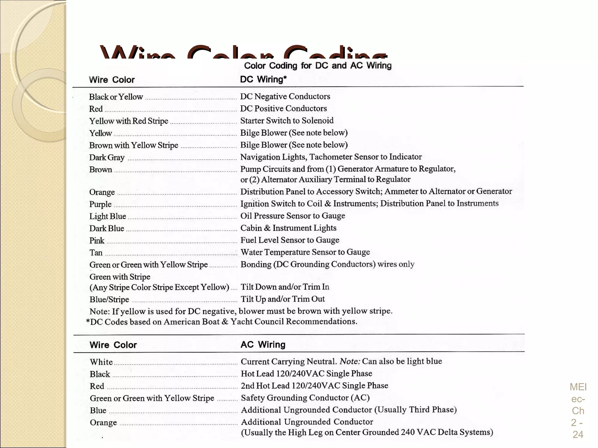
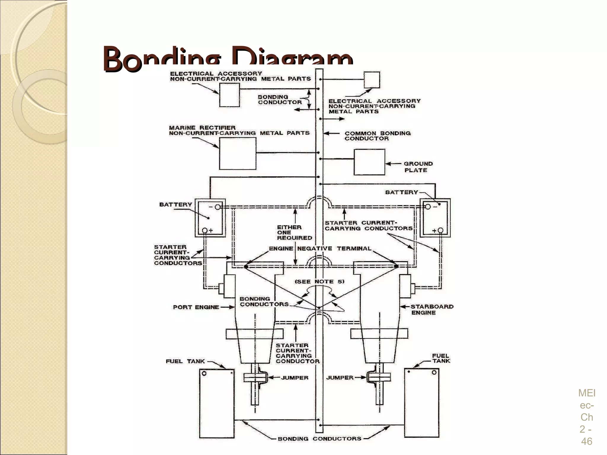
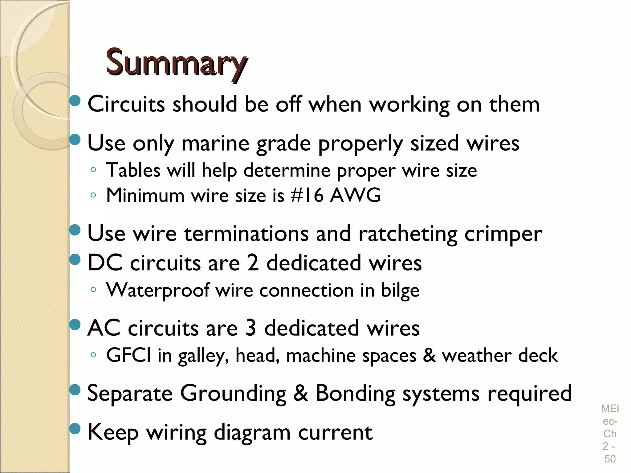
SlideShare a Scribd company logo
Chapter 2Chapter 2
Electrical Wiring Practices
and Diagrams
MEl
ec-
Ch
2 -
1
OverviewOverview
Safety
Standards
Wiring Considerations
Wire Terminations
Coaxial Cable
Wiring Installations
Wiring Diagrams
MEl
ec-
Ch
2 -
2
SafetySafety
Lethal Current
Safety Precautions
MEl
ec-
Ch
2 -
3
Lethal CurrentLethal Current
Fundamental policy of the USPS is SAFETY
Human Body
◦ Resistance – 4 KΩ (moist skin) to 24 KΩ (dry skin)
◦ Safe current (through chest) – less than 20 milliamps
◦ E = 120 VAC R = 4 KΩ I = ?
◦ I = 30 milliamps - NOT SAFE
◦ Don’t want current through chest cavity (may be lethal)
MEl
ec-
Ch
2 -
4
Safety PrecautionsSafety Precautions
Turn circuit off
◦ Disconnect service cord
◦ Disconnect negative battery cable
If must work on live AC circuit
◦ Need 2nd
safety person
Remove metal jewelry
Know your boat and its wiring
Use outlet tester on AC outlets
Use 3-wire extension cord from GFI outlet MEl
ec-
Ch
2 -
5
StandardsStandards
American Boat and Yacht Council (ABYC)
◦ AC and DC Electrical Systems is E-11
◦ Minimum standards
 Construction
 Repair
Marine Dept. of Underwriters Laboratory
◦ Test and certify commercial products
◦ Safety, not function
MEl
ec-
Ch
2 -
6
Wiring ConsiderationsWiring Considerations
Conductors
Wire Types
Wire Size
Wire Insulation
Wire Color Code
MEl
ec-
Ch
2 -
7
ConductorsConductors
Connects power sources to power loads
Characteristics
◦ Safe
◦ Dependable
◦ Efficient (minimal voltage drop)
Boat environment
◦ Worse than either house or car
◦ High humidity
◦ Vibration
◦ Corrosive conditions
MEl
ec-
Ch
2 -
8
WireTypesWireTypes
Marine Grade
◦ Type 3 is recommended
Stranded copper
◦ Tinned is preferred
MEl
ec-
Ch
2 -
9
Wire SizeWire Size
3% voltage drop
◦ Critical circuits (Nav lights)
◦ Electronic Equipment
10% voltage drop
◦ Cabin lights
◦ Motorized Equipment
Minimum size AWG # 16
MEl
ec-
Ch
2 -
10
Wire Has ResistanceWire Has Resistance
Inadvertent Resistors
◦ Wire too small (min of #16 - properly size using table)
◦ Bad connections (or corroded connections)
 Clean and tighten battery connectors
 Tighten lug screws and inspect wire to lug connection
◦ Why do wires get warm / hot?
 Low resistance circuits pass high current (P = I2
x R)
 Wires can account for much of the overall resistance
MEl
ec-
Ch
2 -
11
V12 VDC
0.1 Ώ
0.1 Ώ
10A What Voltage?
An. 10 VDC
Wire Size ComparisonWire Size Comparison
MEl
ec-
Ch
2 -
12
#16 top to #10 bottom
#2 top to #10 bottom
Copper Wire CharacteristicsCopper Wire Characteristics
MEl
ec-
Ch
2 -
13
12- VDC Wire Size Selection12- VDC Wire Size Selection
MEl
ec-
Ch
2 -
14
12 VDC Wire Size Selection12 VDC Wire Size Selection
MEl
ec-
Ch
2 -
15
120 VAC Wire Size Selection120 VAC Wire Size Selection
MEl
ec-
Ch
2 -
16
What Size Wires?What Size Wires?
MEl
ec-
Ch
2 -
17
B
Step 1Step 1
MEl
ec-
Ch
2 -
18
What current to Load?
From Table 2-3 – Maximum of 44 feet (for 10A in #16 wire)
P = E * I I = P / E I = 1200/120
I = 10 Amps
From Table 2-1 – For 10A need #16 wire
B
Step 1 AnswersStep 1 Answers
MEl
ec-
Ch
2 -
19
AMPACITY
10 Amperes
#16 AWG TW
by Table 2-1
for 3% voltage drop
44 feet maximum
by Table 2-3
B
Step 2Step 2
MEl
ec-
Ch
2 -
20
What current to Inverter?
From Table 2-3 – Maximum of 14 feet (for 110A in #1 wire)
Iload = Iout = Iin *0.91 Iin = Iout / 0.91 = 100 / 0.91 = 110 Amps
From Table 2-1 – For 110A need #1 wire
B
Iload = 100 Amps @ 12 V
Step 2 AnswersStep 2 Answers
MEl
ec-
Ch
2 -
21
AMPACITY
110 Amperes
#1 AWG TW
by Table 1
for 3% voltage drop
14 feet maximum
by Table 2-2A
B
Wire InsulationWire Insulation
AC cables must be type UL 1426 BC
◦ 600 volt insulation
◦ Gasoline and Oil resistant
◦ Won’t absorb moisture
DC wires & cables must be Marine Grade
◦ 600 volt insulation
◦ Gasoline and Oil resistant
◦ Won’t absorb moisture
Color coded wires MEl
ec-
Ch
2 -
22
Wire Color CodeWire Color Code
Color AC (Hot) AC (Neut) AC (Gnd) DC + DC -
Black X X1
White X
Green (may have a yellow stripe) X
Red X2
X
Yellow X1
Footnotes:
1 – Yellow preferred for DC negative to avoid confusion with AC Hot wire
2 – 2nd
hot wire in 220 VAC is Red
MEl
ec-
Ch
2 -
23
Wire Color CodingWire Color Coding
MEl
ec-
Ch
2 -
24
Wire TerminationsWire Terminations
Crimping
◦ Special Tool
◦ Approved Marine Connectors
◦ Use of Ratcheting Tool
Solder
Heat-shrink Tubing
MEl
ec-
Ch
2 -
25
Wire TerminalsWire Terminals
MEl
ec-
Ch
2 -
26
Ratcheting CrimperRatcheting Crimper
MEl
ec-
Ch
2 -
27
YES
NO
Ratcheting Tool UseRatcheting Tool Use
First select appropriate connector
Strip insulation length of stem plus 1/16”
Insert stripped end all way into terminal
◦ End should extend 1/16”
Place terminal in same color slot
◦ First crimp end of terminal barrel nearest ring
◦ Then crimp wire end of terminal barrel
Check the connection with a solid tug
MEl
ec-
Ch
2 -
28
SolderingSoldering
Terminal connection can’t be only soldered
◦ Must also be crimped
Soldering is normally not required
◦ Crimped connectors are acceptable to ABYC
◦ If solder, apply only to ring end of terminal
Solder changes stranded wire into solid
◦ Stranded wire is flexible
Use 40% lead / 60% tin, rosin core solder
Battery lugs may be only soldered
MEl
ec-
Ch
2 -
29
Heat-Shrink TubingHeat-Shrink Tubing
MEl
ec-
Ch
2 -
30
Application Steps
Coaxial CableCoaxial Cable
Antenna cable
Radio coax is 50 ohm with PL-259
Radio cable is cut to length
Want attenuation under 3 db
TV cable is 75 ohm with “F” connectors
GPS cable is not cut to length
◦ Coil excess in 1-foot loops
MEl
ec-
Ch
2 -
31
Coaxial Cable InformationCoaxial Cable Information
MEl
ec-
Ch
2 -
32
Soldering PL-259 ConnectorSoldering PL-259 Connector
MEl
ec-
Ch
2 -
33
Wiring InstallationWiring Installation
Basic Considerations
Distribution Panel
Fuses / Circuit Breakers
Branch Circuits
◦ Wire
◦ Outlets
◦ Switches
Grounding Systems
Bonding Systems MEl
ec-
Ch
2 -
34
Basic ConsiderationsBasic Considerations
Must have source and return wires
◦ Return wires to a common point
◦ May use feeder wire from power panel for:
 engine, helm console, etc.
Wires above flood level of bilge
◦ Waterproof if in bilge
Insulated support every 18”
Twist DC wires within 1 meter of compass
MEl
ec-
Ch
2 -
35
Distribution PanelDistribution Panel
Central location of Circuit Breakers / Fuses
◦ All branch circuits from this location
AC and DC may be combined in one panel
All equipment / circuits should go to panel
◦ Not direct to battery (except bilge pump)
 Noise interference suppression covered in Section 7
MEl
ec-
Ch
2 -
36
DC / AC Power PanelDC / AC Power Panel
MEl
ec-
Ch
2 -
37
Front View
Inside Power PanelInside Power Panel
MEl
ec-
Ch
2 -
38DC Side
Buss Bars
Fuses and Circuit BreakersFuses and Circuit Breakers
Used to protect wiring from over current
◦ In positive or hot wire
Newer boats use circuit breakers
◦ Initially more expensive
Replace blown fuse with correct rating
Circuit Breakers should be Marine Grade
◦ Trip free
◦ Manual reset
MEl
ec-
Ch
2 -
39
Branch Circuits - WiresBranch Circuits - Wires
Minimum size is 16 AWG
◦ See Wire Selection Tables
◦ For AC normally #14 for 15A and #12 for 20A
Must terminate in closed electrical box
Of sufficient length
DC negative returned to DC Panel
◦ May use several negative feeder terminals
AC neutrals returned to AC Panel
Bonding system never used as return wire
MEl
ec-
Ch
2 -
40
Branch Circuits - OutletsBranch Circuits - Outlets
120 VAC outlets must be 3-wire polarized
◦ Black (hot) to brass or copper colored terminal
Outlet wires must have crimp terminals
GFI outlets
◦ Required on weather deck, head, galley and
machinery spaces
◦ Good practice for all AC outlets to be GFI
◦ Trip at 5 milliamps
Different outlets for AC and DC power MEl
ec-
Ch
2 -
41
Outlets and PlugsOutlets and Plugs
MEl
ec-
Ch
2 -
42
DC Outlet
(Receptacle)
DC Plug
120 VAC 120 VAC12 VDC 120 VAC
15 A Outlet
AC Plug 15 A AC Plug 20 A
GFI 15 A
Outlet
20 A Outlet
Branch Circuits - SwitchesBranch Circuits - Switches
Modern panels use Circuit Breakers
◦ Which also double as switches
Switches / Circuit Breakers
◦ Must be Marine Grade
◦ Rated for the voltage and current controlled
◦ Interrupt the positive (DC) or hot (AC) leg
Battery Switch
◦ Designed for high current service
◦ Not located in engine or fuel-tank compartments MEl
ec-
Ch
2 -
43
Grounding SystemGrounding System
Ground is potential of water around boat
◦ Or potential of earth’s surface
DC – Ground Battery negative terminal(s)
◦ Also engine block
◦ Wire color is Yellow (or Black)
AC – Transformer center tap on shore
◦ Also connected to ground rod at transformer
◦ Wire color is Green and uninterrupted wire
 Isolation transformers and galvanic isolators are exception
and covered in Chapter 4 on AC
Engine, DC negative & AC ground connected
MEl
ec-
Ch
2 -
44
Bonding SystemBonding System
For lightning protection
◦ More in Chapter 6
All metal objects should be bonded
◦ Keeps all metal at zero potential
◦ Engine blocks
◦ Battery negative terminals
Non-current carrying wire
Through-hull fittings
◦ ABYC now recommends they be bonded
◦ Electrically isolated from metal hull MEl
ec-
Ch
2 -
45
Bonding DiagramBonding Diagram
MEl
ec-
Ch
2 -
46
Wiring DiagramsWiring Diagrams
Elements of a Good Wiring Diagram
◦ Documents boat’s electrical layout
◦ Should be kept current
◦ Used for troubleshooting
Component Identification
◦ Physical objects to their symbol
◦ Wires are color coded
MEl
ec-
Ch
2 -
47
Wiring Diagram SymbolsWiring Diagram Symbols
MEl
ec-
Ch
2 -
48
Switch, double pole, single throw (DPST)
Switch, single pole, single throw (SPST)
Switch, single pole, double throw (SPDT)
Battery (long line on top is positive)
Wires connected (at dots)
Wires crossing (but NOT connected)
Wire (insulated, metal conductor)
Incandescent Light
Alternate symbol for Light
Circuit Breaker
Fuse
Ground
Male Connector
Female Connector
Simple DC Wiring DiagramSimple DC Wiring Diagram
MEl
ec-
Ch
2 -
49
SummarySummary
Circuits should be off when working on them
Use only marine grade properly sized wires
◦ Tables will help determine proper wire size
◦ Minimum wire size is #16 AWG
Use wire terminations and ratcheting crimper
DC circuits are 2 dedicated wires
◦ Waterproof wire connection in bilge
AC circuits are 3 dedicated wires
◦ GFCI in galley, head, machine spaces & weather deck
Separate Grounding & Bonding systems required
Keep wiring diagram current
MEl
ec-
Ch
2 -
50

More Related Content

What's hot

Electrical Installation PPT (Basic Electrical Engineering)
Electrical Installation PPT (Basic Electrical Engineering)Electrical Installation PPT (Basic Electrical Engineering)
Electrical Installation PPT (Basic Electrical Engineering)
Dhrumil Maniar
 
Electrical System Design
Electrical System Design Electrical System Design
Design considerations of electrical installations
Design considerations of electrical installationsDesign considerations of electrical installations
Design considerations of electrical installations
vishalgohel12195
 
Electrical
ElectricalElectrical
2nd Quarter - L1 - Electrical Symbols.pptx
2nd Quarter - L1 - Electrical Symbols.pptx2nd Quarter - L1 - Electrical Symbols.pptx
2nd Quarter - L1 - Electrical Symbols.pptx
MarioFlores379116
 
Types of conduits
Types of conduitsTypes of conduits
Types of conduits
VenerandoPanday
 
Electrical wiring
Electrical wiringElectrical wiring
System of wiring
System of wiringSystem of wiring
System of wiring
Darshan Doshi
 
Types of wires,cables,connectors and switches
Types of wires,cables,connectors and switchesTypes of wires,cables,connectors and switches
Types of wires,cables,connectors and switches
Akash Gajjar
 
HOME WIRING(domestic wiring)
HOME WIRING(domestic wiring)HOME WIRING(domestic wiring)
HOME WIRING(domestic wiring)
Arshad Hussain
 
Residential Electrical Wiring Systems Basics
Residential Electrical Wiring Systems Basics Residential Electrical Wiring Systems Basics
Residential Electrical Wiring Systems Basics
Dr.Raja R
 
Electrical protective devices ec
Electrical protective devices ecElectrical protective devices ec
Electrical protective devices ec
trg12345
 
Wires and cables
Wires and cablesWires and cables
Wires and cables
CLIFFORD BRANDES
 
Types of Wires and Cables
Types of Wires and CablesTypes of Wires and Cables
Types of Wires and Cables
Osama Naseem
 
Electrical signs and symbols
Electrical signs and symbolsElectrical signs and symbols
Electrical signs and symbols
Mary Grace Anticuando
 
Domestic wiring
Domestic wiringDomestic wiring
Domestic wiring
Vima Mali
 
Types of wiring diagram 22.pptx
Types of wiring diagram 22.pptxTypes of wiring diagram 22.pptx
Types of wiring diagram 22.pptx
JasonPDelosSantos
 
1 Conduit PEC.pptx
1 Conduit PEC.pptx1 Conduit PEC.pptx
1 Conduit PEC.pptx
Victor Rosales
 
Electrical Supplies and Materials (EIM)
Electrical Supplies and Materials (EIM)Electrical Supplies and Materials (EIM)
Electrical Supplies and Materials (EIM)
Jelo Fojas
 
Electrical symbols
Electrical symbols Electrical symbols
Electrical symbols
Sanchit Kanwar
 

What's hot (20)

Electrical Installation PPT (Basic Electrical Engineering)
Electrical Installation PPT (Basic Electrical Engineering)Electrical Installation PPT (Basic Electrical Engineering)
Electrical Installation PPT (Basic Electrical Engineering)
 
Electrical System Design
Electrical System Design Electrical System Design
Electrical System Design
 
Design considerations of electrical installations
Design considerations of electrical installationsDesign considerations of electrical installations
Design considerations of electrical installations
 
Electrical
ElectricalElectrical
Electrical
 
2nd Quarter - L1 - Electrical Symbols.pptx
2nd Quarter - L1 - Electrical Symbols.pptx2nd Quarter - L1 - Electrical Symbols.pptx
2nd Quarter - L1 - Electrical Symbols.pptx
 
Types of conduits
Types of conduitsTypes of conduits
Types of conduits
 
Electrical wiring
Electrical wiringElectrical wiring
Electrical wiring
 
System of wiring
System of wiringSystem of wiring
System of wiring
 
Types of wires,cables,connectors and switches
Types of wires,cables,connectors and switchesTypes of wires,cables,connectors and switches
Types of wires,cables,connectors and switches
 
HOME WIRING(domestic wiring)
HOME WIRING(domestic wiring)HOME WIRING(domestic wiring)
HOME WIRING(domestic wiring)
 
Residential Electrical Wiring Systems Basics
Residential Electrical Wiring Systems Basics Residential Electrical Wiring Systems Basics
Residential Electrical Wiring Systems Basics
 
Electrical protective devices ec
Electrical protective devices ecElectrical protective devices ec
Electrical protective devices ec
 
Wires and cables
Wires and cablesWires and cables
Wires and cables
 
Types of Wires and Cables
Types of Wires and CablesTypes of Wires and Cables
Types of Wires and Cables
 
Electrical signs and symbols
Electrical signs and symbolsElectrical signs and symbols
Electrical signs and symbols
 
Domestic wiring
Domestic wiringDomestic wiring
Domestic wiring
 
Types of wiring diagram 22.pptx
Types of wiring diagram 22.pptxTypes of wiring diagram 22.pptx
Types of wiring diagram 22.pptx
 
1 Conduit PEC.pptx
1 Conduit PEC.pptx1 Conduit PEC.pptx
1 Conduit PEC.pptx
 
Electrical Supplies and Materials (EIM)
Electrical Supplies and Materials (EIM)Electrical Supplies and Materials (EIM)
Electrical Supplies and Materials (EIM)
 
Electrical symbols
Electrical symbols Electrical symbols
Electrical symbols
 

Viewers also liked

Partial differentiation B tech
Partial differentiation B techPartial differentiation B tech
Partial differentiation B tech
Raj verma
 
Electrical wiring BY Jemish
Electrical wiring BY JemishElectrical wiring BY Jemish
Electrical wiring BY Jemish
Goti Jemish
 
Taylor and Maclaurin Series
Taylor and Maclaurin SeriesTaylor and Maclaurin Series
Taylor and Maclaurin Series
Harsh Pathak
 
Taylor series and maclaurin with exercices
Taylor series and maclaurin with exercicesTaylor series and maclaurin with exercices
Taylor series and maclaurin with exercicesHernanFula
 
Taylor series in 1 and 2 variable
Taylor series in 1 and 2 variableTaylor series in 1 and 2 variable
Taylor series in 1 and 2 variable
gidc engineering college
 
Taylor and maclaurian series
Taylor and maclaurian seriesTaylor and maclaurian series
Taylor and maclaurian series
Nishant Patel
 
B tech ee ii_ eee_ u-4_ transformer & electrical wiring_dipen patel
B tech ee  ii_ eee_ u-4_ transformer & electrical wiring_dipen patelB tech ee  ii_ eee_ u-4_ transformer & electrical wiring_dipen patel
B tech ee ii_ eee_ u-4_ transformer & electrical wiring_dipen patel
Rai University
 
Electrical Systems in a Building
Electrical Systems in a BuildingElectrical Systems in a Building
Electrical Systems in a Building
GAURAV. H .TANDON
 
K-12 Module in TLE 8 (Electrical) 3rd Grading
K-12 Module in TLE 8 (Electrical) 3rd GradingK-12 Module in TLE 8 (Electrical) 3rd Grading
K-12 Module in TLE 8 (Electrical) 3rd GradingDaniel Manaog
 
Building Services Engg. (Electrical installations)
Building Services Engg. (Electrical installations)Building Services Engg. (Electrical installations)
Building Services Engg. (Electrical installations)Ritesh Ambadkar
 
Building Services Electrical (MEP)
Building Services Electrical (MEP)Building Services Electrical (MEP)
Building Services Electrical (MEP)
Manoj Mawle
 

Viewers also liked (12)

Partial differentiation B tech
Partial differentiation B techPartial differentiation B tech
Partial differentiation B tech
 
Electrical wiring BY Jemish
Electrical wiring BY JemishElectrical wiring BY Jemish
Electrical wiring BY Jemish
 
Taylor series
Taylor seriesTaylor series
Taylor series
 
Taylor and Maclaurin Series
Taylor and Maclaurin SeriesTaylor and Maclaurin Series
Taylor and Maclaurin Series
 
Taylor series and maclaurin with exercices
Taylor series and maclaurin with exercicesTaylor series and maclaurin with exercices
Taylor series and maclaurin with exercices
 
Taylor series in 1 and 2 variable
Taylor series in 1 and 2 variableTaylor series in 1 and 2 variable
Taylor series in 1 and 2 variable
 
Taylor and maclaurian series
Taylor and maclaurian seriesTaylor and maclaurian series
Taylor and maclaurian series
 
B tech ee ii_ eee_ u-4_ transformer & electrical wiring_dipen patel
B tech ee  ii_ eee_ u-4_ transformer & electrical wiring_dipen patelB tech ee  ii_ eee_ u-4_ transformer & electrical wiring_dipen patel
B tech ee ii_ eee_ u-4_ transformer & electrical wiring_dipen patel
 
Electrical Systems in a Building
Electrical Systems in a BuildingElectrical Systems in a Building
Electrical Systems in a Building
 
K-12 Module in TLE 8 (Electrical) 3rd Grading
K-12 Module in TLE 8 (Electrical) 3rd GradingK-12 Module in TLE 8 (Electrical) 3rd Grading
K-12 Module in TLE 8 (Electrical) 3rd Grading
 
Building Services Engg. (Electrical installations)
Building Services Engg. (Electrical installations)Building Services Engg. (Electrical installations)
Building Services Engg. (Electrical installations)
 
Building Services Electrical (MEP)
Building Services Electrical (MEP)Building Services Electrical (MEP)
Building Services Electrical (MEP)
 

Similar to Electrical Wiring Practices and Diagrams

3560357.ppt
3560357.ppt3560357.ppt
3560357.ppt
SMARTENGRZ
 
Substation.ppt
Substation.pptSubstation.ppt
Substation.ppt
PrakashJindani
 
PE1-SCRs.pdf
PE1-SCRs.pdfPE1-SCRs.pdf
PE1-SCRs.pdf
yogeshkute
 
Eaton-Product-Aid
Eaton-Product-AidEaton-Product-Aid
Eaton-Product-AidJoe Galuska
 
220 KV Substation Operation & Maintenance
220 KV Substation Operation & Maintenance220 KV Substation Operation & Maintenance
220 KV Substation Operation & Maintenance
Himansu Pradhan
 
PCB Layout guidelines.pdf
PCB Layout guidelines.pdfPCB Layout guidelines.pdf
PCB Layout guidelines.pdf
ssuserf36d4d1
 
CHAPTER 2 Design of Building Electrical Systems (2).pptx.pptx
CHAPTER 2 Design of Building Electrical Systems (2).pptx.pptxCHAPTER 2 Design of Building Electrical Systems (2).pptx.pptx
CHAPTER 2 Design of Building Electrical Systems (2).pptx.pptx
LiewChiaPing
 
Ferrite Specifications and ACME Ferrites (2)
Ferrite Specifications and ACME Ferrites (2)Ferrite Specifications and ACME Ferrites (2)
Ferrite Specifications and ACME Ferrites (2)Ray Lai
 
industrial training on 132 kv substation
industrial training on 132 kv substationindustrial training on 132 kv substation
industrial training on 132 kv substation
pk130992
 
Technician Training: Wiring Basics
Technician Training: Wiring BasicsTechnician Training: Wiring Basics
Technician Training: Wiring Basics
Earthsafe Systems, Inc.
 
Power System Protection
Power System ProtectionPower System Protection
Power System Protection
Sumeet Ratnawat
 
power electronics FiringCkt.pdf.crdownload.pptx
power electronics FiringCkt.pdf.crdownload.pptxpower electronics FiringCkt.pdf.crdownload.pptx
power electronics FiringCkt.pdf.crdownload.pptx
divakarrvl
 
L03.1 l aa tv philips
L03.1 l aa tv philipsL03.1 l aa tv philips
L03.1 l aa tv philips
Perfumeria Rachel
 
Contactor hoangphuongjsc.com
Contactor   hoangphuongjsc.comContactor   hoangphuongjsc.com
Contactor hoangphuongjsc.com
Hoàng Phương JSC
 
MV Switchgear from IEEE
MV Switchgear from IEEEMV Switchgear from IEEE
KL1034 Lect2 Electrical wiring.pdf
KL1034 Lect2 Electrical wiring.pdfKL1034 Lect2 Electrical wiring.pdf
KL1034 Lect2 Electrical wiring.pdf
SysteDesig
 
Thyristors (2)
Thyristors (2)Thyristors (2)
Thyristors (2)Chethan Sp
 

Similar to Electrical Wiring Practices and Diagrams (20)

3560357.ppt
3560357.ppt3560357.ppt
3560357.ppt
 
Substation.ppt
Substation.pptSubstation.ppt
Substation.ppt
 
PE1-SCRs.pdf
PE1-SCRs.pdfPE1-SCRs.pdf
PE1-SCRs.pdf
 
Eaton-Product-Aid
Eaton-Product-AidEaton-Product-Aid
Eaton-Product-Aid
 
220 KV Substation Operation & Maintenance
220 KV Substation Operation & Maintenance220 KV Substation Operation & Maintenance
220 KV Substation Operation & Maintenance
 
PCB Layout guidelines.pdf
PCB Layout guidelines.pdfPCB Layout guidelines.pdf
PCB Layout guidelines.pdf
 
CHAPTER 2 Design of Building Electrical Systems (2).pptx.pptx
CHAPTER 2 Design of Building Electrical Systems (2).pptx.pptxCHAPTER 2 Design of Building Electrical Systems (2).pptx.pptx
CHAPTER 2 Design of Building Electrical Systems (2).pptx.pptx
 
Consumer unit
Consumer unitConsumer unit
Consumer unit
 
Ferrite Specifications and ACME Ferrites (2)
Ferrite Specifications and ACME Ferrites (2)Ferrite Specifications and ACME Ferrites (2)
Ferrite Specifications and ACME Ferrites (2)
 
User manual-part-2-3501466
User manual-part-2-3501466User manual-part-2-3501466
User manual-part-2-3501466
 
industrial training on 132 kv substation
industrial training on 132 kv substationindustrial training on 132 kv substation
industrial training on 132 kv substation
 
Technician Training: Wiring Basics
Technician Training: Wiring BasicsTechnician Training: Wiring Basics
Technician Training: Wiring Basics
 
Power System Protection
Power System ProtectionPower System Protection
Power System Protection
 
power electronics FiringCkt.pdf.crdownload.pptx
power electronics FiringCkt.pdf.crdownload.pptxpower electronics FiringCkt.pdf.crdownload.pptx
power electronics FiringCkt.pdf.crdownload.pptx
 
MAN0824-01
MAN0824-01MAN0824-01
MAN0824-01
 
L03.1 l aa tv philips
L03.1 l aa tv philipsL03.1 l aa tv philips
L03.1 l aa tv philips
 
Contactor hoangphuongjsc.com
Contactor   hoangphuongjsc.comContactor   hoangphuongjsc.com
Contactor hoangphuongjsc.com
 
MV Switchgear from IEEE
MV Switchgear from IEEEMV Switchgear from IEEE
MV Switchgear from IEEE
 
KL1034 Lect2 Electrical wiring.pdf
KL1034 Lect2 Electrical wiring.pdfKL1034 Lect2 Electrical wiring.pdf
KL1034 Lect2 Electrical wiring.pdf
 
Thyristors (2)
Thyristors (2)Thyristors (2)
Thyristors (2)
 

More from Practicing In Some Infra Company

Thermal Insulation Understanding and Techniques
Thermal Insulation Understanding and TechniquesThermal Insulation Understanding and Techniques
Thermal Insulation Understanding and Techniques
Practicing In Some Infra Company
 
Slums
SlumsSlums
Remote sensing
Remote sensingRemote sensing
Types of wires and cables
Types of wires and cablesTypes of wires and cables
Types of wires and cables
Practicing In Some Infra Company
 
Types of excavating tools and machine
Types of excavating tools and machineTypes of excavating tools and machine
Types of excavating tools and machine
Practicing In Some Infra Company
 
flyover and bridge problems and its solutions
flyover and bridge problems and its solutionsflyover and bridge problems and its solutions
flyover and bridge problems and its solutions
Practicing In Some Infra Company
 
Flood
FloodFlood
Water softing by reverse osmosis method
Water softing by reverse osmosis methodWater softing by reverse osmosis method
Water softing by reverse osmosis method
Practicing In Some Infra Company
 
Engineering graphics
Engineering graphicsEngineering graphics
Engineering graphics
Practicing In Some Infra Company
 
Flyover bridge
Flyover bridgeFlyover bridge
Contributor personality development
Contributor personality developmentContributor personality development
Contributor personality development
Practicing In Some Infra Company
 

More from Practicing In Some Infra Company (11)

Thermal Insulation Understanding and Techniques
Thermal Insulation Understanding and TechniquesThermal Insulation Understanding and Techniques
Thermal Insulation Understanding and Techniques
 
Slums
SlumsSlums
Slums
 
Remote sensing
Remote sensingRemote sensing
Remote sensing
 
Types of wires and cables
Types of wires and cablesTypes of wires and cables
Types of wires and cables
 
Types of excavating tools and machine
Types of excavating tools and machineTypes of excavating tools and machine
Types of excavating tools and machine
 
flyover and bridge problems and its solutions
flyover and bridge problems and its solutionsflyover and bridge problems and its solutions
flyover and bridge problems and its solutions
 
Flood
FloodFlood
Flood
 
Water softing by reverse osmosis method
Water softing by reverse osmosis methodWater softing by reverse osmosis method
Water softing by reverse osmosis method
 
Engineering graphics
Engineering graphicsEngineering graphics
Engineering graphics
 
Flyover bridge
Flyover bridgeFlyover bridge
Flyover bridge
 
Contributor personality development
Contributor personality developmentContributor personality development
Contributor personality development
 

Recently uploaded

Democratizing Fuzzing at Scale by Abhishek Arya
Democratizing Fuzzing at Scale by Abhishek AryaDemocratizing Fuzzing at Scale by Abhishek Arya
Democratizing Fuzzing at Scale by Abhishek Arya
abh.arya
 
NO1 Uk best vashikaran specialist in delhi vashikaran baba near me online vas...
NO1 Uk best vashikaran specialist in delhi vashikaran baba near me online vas...NO1 Uk best vashikaran specialist in delhi vashikaran baba near me online vas...
NO1 Uk best vashikaran specialist in delhi vashikaran baba near me online vas...
Amil Baba Dawood bangali
 
Halogenation process of chemical process industries
Halogenation process of chemical process industriesHalogenation process of chemical process industries
Halogenation process of chemical process industries
MuhammadTufail242431
 
H.Seo, ICLR 2024, MLILAB, KAIST AI.pdf
H.Seo,  ICLR 2024, MLILAB,  KAIST AI.pdfH.Seo,  ICLR 2024, MLILAB,  KAIST AI.pdf
H.Seo, ICLR 2024, MLILAB, KAIST AI.pdf
MLILAB
 
Hybrid optimization of pumped hydro system and solar- Engr. Abdul-Azeez.pdf
Hybrid optimization of pumped hydro system and solar- Engr. Abdul-Azeez.pdfHybrid optimization of pumped hydro system and solar- Engr. Abdul-Azeez.pdf
Hybrid optimization of pumped hydro system and solar- Engr. Abdul-Azeez.pdf
fxintegritypublishin
 
Gen AI Study Jams _ For the GDSC Leads in India.pdf
Gen AI Study Jams _ For the GDSC Leads in India.pdfGen AI Study Jams _ For the GDSC Leads in India.pdf
Gen AI Study Jams _ For the GDSC Leads in India.pdf
gdsczhcet
 
Sachpazis:Terzaghi Bearing Capacity Estimation in simple terms with Calculati...
Sachpazis:Terzaghi Bearing Capacity Estimation in simple terms with Calculati...Sachpazis:Terzaghi Bearing Capacity Estimation in simple terms with Calculati...
Sachpazis:Terzaghi Bearing Capacity Estimation in simple terms with Calculati...
Dr.Costas Sachpazis
 
DESIGN A COTTON SEED SEPARATION MACHINE.docx
DESIGN A COTTON SEED SEPARATION MACHINE.docxDESIGN A COTTON SEED SEPARATION MACHINE.docx
DESIGN A COTTON SEED SEPARATION MACHINE.docx
FluxPrime1
 
road safety engineering r s e unit 3.pdf
road safety engineering  r s e unit 3.pdfroad safety engineering  r s e unit 3.pdf
road safety engineering r s e unit 3.pdf
VENKATESHvenky89705
 
Top 10 Oil and Gas Projects in Saudi Arabia 2024.pdf
Top 10 Oil and Gas Projects in Saudi Arabia 2024.pdfTop 10 Oil and Gas Projects in Saudi Arabia 2024.pdf
Top 10 Oil and Gas Projects in Saudi Arabia 2024.pdf
Teleport Manpower Consultant
 
Design and Analysis of Algorithms-DP,Backtracking,Graphs,B&B
Design and Analysis of Algorithms-DP,Backtracking,Graphs,B&BDesign and Analysis of Algorithms-DP,Backtracking,Graphs,B&B
Design and Analysis of Algorithms-DP,Backtracking,Graphs,B&B
Sreedhar Chowdam
 
Event Management System Vb Net Project Report.pdf
Event Management System Vb Net  Project Report.pdfEvent Management System Vb Net  Project Report.pdf
Event Management System Vb Net Project Report.pdf
Kamal Acharya
 
CFD Simulation of By-pass Flow in a HRSG module by R&R Consult.pptx
CFD Simulation of By-pass Flow in a HRSG module by R&R Consult.pptxCFD Simulation of By-pass Flow in a HRSG module by R&R Consult.pptx
CFD Simulation of By-pass Flow in a HRSG module by R&R Consult.pptx
R&R Consult
 
Architectural Portfolio Sean Lockwood
Architectural Portfolio Sean LockwoodArchitectural Portfolio Sean Lockwood
Architectural Portfolio Sean Lockwood
seandesed
 
Industrial Training at Shahjalal Fertilizer Company Limited (SFCL)
Industrial Training at Shahjalal Fertilizer Company Limited (SFCL)Industrial Training at Shahjalal Fertilizer Company Limited (SFCL)
Industrial Training at Shahjalal Fertilizer Company Limited (SFCL)
MdTanvirMahtab2
 
Vaccine management system project report documentation..pdf
Vaccine management system project report documentation..pdfVaccine management system project report documentation..pdf
Vaccine management system project report documentation..pdf
Kamal Acharya
 
Nuclear Power Economics and Structuring 2024
Nuclear Power Economics and Structuring 2024Nuclear Power Economics and Structuring 2024
Nuclear Power Economics and Structuring 2024
Massimo Talia
 
ethical hacking-mobile hacking methods.ppt
ethical hacking-mobile hacking methods.pptethical hacking-mobile hacking methods.ppt
ethical hacking-mobile hacking methods.ppt
Jayaprasanna4
 
ASME IX(9) 2007 Full Version .pdf
ASME IX(9)  2007 Full Version       .pdfASME IX(9)  2007 Full Version       .pdf
ASME IX(9) 2007 Full Version .pdf
AhmedHussein950959
 
Railway Signalling Principles Edition 3.pdf
Railway Signalling Principles Edition 3.pdfRailway Signalling Principles Edition 3.pdf
Railway Signalling Principles Edition 3.pdf
TeeVichai
 

Recently uploaded (20)

Democratizing Fuzzing at Scale by Abhishek Arya
Democratizing Fuzzing at Scale by Abhishek AryaDemocratizing Fuzzing at Scale by Abhishek Arya
Democratizing Fuzzing at Scale by Abhishek Arya
 
NO1 Uk best vashikaran specialist in delhi vashikaran baba near me online vas...
NO1 Uk best vashikaran specialist in delhi vashikaran baba near me online vas...NO1 Uk best vashikaran specialist in delhi vashikaran baba near me online vas...
NO1 Uk best vashikaran specialist in delhi vashikaran baba near me online vas...
 
Halogenation process of chemical process industries
Halogenation process of chemical process industriesHalogenation process of chemical process industries
Halogenation process of chemical process industries
 
H.Seo, ICLR 2024, MLILAB, KAIST AI.pdf
H.Seo,  ICLR 2024, MLILAB,  KAIST AI.pdfH.Seo,  ICLR 2024, MLILAB,  KAIST AI.pdf
H.Seo, ICLR 2024, MLILAB, KAIST AI.pdf
 
Hybrid optimization of pumped hydro system and solar- Engr. Abdul-Azeez.pdf
Hybrid optimization of pumped hydro system and solar- Engr. Abdul-Azeez.pdfHybrid optimization of pumped hydro system and solar- Engr. Abdul-Azeez.pdf
Hybrid optimization of pumped hydro system and solar- Engr. Abdul-Azeez.pdf
 
Gen AI Study Jams _ For the GDSC Leads in India.pdf
Gen AI Study Jams _ For the GDSC Leads in India.pdfGen AI Study Jams _ For the GDSC Leads in India.pdf
Gen AI Study Jams _ For the GDSC Leads in India.pdf
 
Sachpazis:Terzaghi Bearing Capacity Estimation in simple terms with Calculati...
Sachpazis:Terzaghi Bearing Capacity Estimation in simple terms with Calculati...Sachpazis:Terzaghi Bearing Capacity Estimation in simple terms with Calculati...
Sachpazis:Terzaghi Bearing Capacity Estimation in simple terms with Calculati...
 
DESIGN A COTTON SEED SEPARATION MACHINE.docx
DESIGN A COTTON SEED SEPARATION MACHINE.docxDESIGN A COTTON SEED SEPARATION MACHINE.docx
DESIGN A COTTON SEED SEPARATION MACHINE.docx
 
road safety engineering r s e unit 3.pdf
road safety engineering  r s e unit 3.pdfroad safety engineering  r s e unit 3.pdf
road safety engineering r s e unit 3.pdf
 
Top 10 Oil and Gas Projects in Saudi Arabia 2024.pdf
Top 10 Oil and Gas Projects in Saudi Arabia 2024.pdfTop 10 Oil and Gas Projects in Saudi Arabia 2024.pdf
Top 10 Oil and Gas Projects in Saudi Arabia 2024.pdf
 
Design and Analysis of Algorithms-DP,Backtracking,Graphs,B&B
Design and Analysis of Algorithms-DP,Backtracking,Graphs,B&BDesign and Analysis of Algorithms-DP,Backtracking,Graphs,B&B
Design and Analysis of Algorithms-DP,Backtracking,Graphs,B&B
 
Event Management System Vb Net Project Report.pdf
Event Management System Vb Net  Project Report.pdfEvent Management System Vb Net  Project Report.pdf
Event Management System Vb Net Project Report.pdf
 
CFD Simulation of By-pass Flow in a HRSG module by R&R Consult.pptx
CFD Simulation of By-pass Flow in a HRSG module by R&R Consult.pptxCFD Simulation of By-pass Flow in a HRSG module by R&R Consult.pptx
CFD Simulation of By-pass Flow in a HRSG module by R&R Consult.pptx
 
Architectural Portfolio Sean Lockwood
Architectural Portfolio Sean LockwoodArchitectural Portfolio Sean Lockwood
Architectural Portfolio Sean Lockwood
 
Industrial Training at Shahjalal Fertilizer Company Limited (SFCL)
Industrial Training at Shahjalal Fertilizer Company Limited (SFCL)Industrial Training at Shahjalal Fertilizer Company Limited (SFCL)
Industrial Training at Shahjalal Fertilizer Company Limited (SFCL)
 
Vaccine management system project report documentation..pdf
Vaccine management system project report documentation..pdfVaccine management system project report documentation..pdf
Vaccine management system project report documentation..pdf
 
Nuclear Power Economics and Structuring 2024
Nuclear Power Economics and Structuring 2024Nuclear Power Economics and Structuring 2024
Nuclear Power Economics and Structuring 2024
 
ethical hacking-mobile hacking methods.ppt
ethical hacking-mobile hacking methods.pptethical hacking-mobile hacking methods.ppt
ethical hacking-mobile hacking methods.ppt
 
ASME IX(9) 2007 Full Version .pdf
ASME IX(9)  2007 Full Version       .pdfASME IX(9)  2007 Full Version       .pdf
ASME IX(9) 2007 Full Version .pdf
 
Railway Signalling Principles Edition 3.pdf
Railway Signalling Principles Edition 3.pdfRailway Signalling Principles Edition 3.pdf
Railway Signalling Principles Edition 3.pdf
 

Electrical Wiring Practices and Diagrams

  • 1. Chapter 2Chapter 2 Electrical Wiring Practices and Diagrams MEl ec- Ch 2 - 1
  • 2. OverviewOverview Safety Standards Wiring Considerations Wire Terminations Coaxial Cable Wiring Installations Wiring Diagrams MEl ec- Ch 2 - 2
  • 4. Lethal CurrentLethal Current Fundamental policy of the USPS is SAFETY Human Body ◦ Resistance – 4 KΩ (moist skin) to 24 KΩ (dry skin) ◦ Safe current (through chest) – less than 20 milliamps ◦ E = 120 VAC R = 4 KΩ I = ? ◦ I = 30 milliamps - NOT SAFE ◦ Don’t want current through chest cavity (may be lethal) MEl ec- Ch 2 - 4
  • 5. Safety PrecautionsSafety Precautions Turn circuit off ◦ Disconnect service cord ◦ Disconnect negative battery cable If must work on live AC circuit ◦ Need 2nd safety person Remove metal jewelry Know your boat and its wiring Use outlet tester on AC outlets Use 3-wire extension cord from GFI outlet MEl ec- Ch 2 - 5
  • 6. StandardsStandards American Boat and Yacht Council (ABYC) ◦ AC and DC Electrical Systems is E-11 ◦ Minimum standards  Construction  Repair Marine Dept. of Underwriters Laboratory ◦ Test and certify commercial products ◦ Safety, not function MEl ec- Ch 2 - 6
  • 7. Wiring ConsiderationsWiring Considerations Conductors Wire Types Wire Size Wire Insulation Wire Color Code MEl ec- Ch 2 - 7
  • 8. ConductorsConductors Connects power sources to power loads Characteristics ◦ Safe ◦ Dependable ◦ Efficient (minimal voltage drop) Boat environment ◦ Worse than either house or car ◦ High humidity ◦ Vibration ◦ Corrosive conditions MEl ec- Ch 2 - 8
  • 9. WireTypesWireTypes Marine Grade ◦ Type 3 is recommended Stranded copper ◦ Tinned is preferred MEl ec- Ch 2 - 9
  • 10. Wire SizeWire Size 3% voltage drop ◦ Critical circuits (Nav lights) ◦ Electronic Equipment 10% voltage drop ◦ Cabin lights ◦ Motorized Equipment Minimum size AWG # 16 MEl ec- Ch 2 - 10
  • 11. Wire Has ResistanceWire Has Resistance Inadvertent Resistors ◦ Wire too small (min of #16 - properly size using table) ◦ Bad connections (or corroded connections)  Clean and tighten battery connectors  Tighten lug screws and inspect wire to lug connection ◦ Why do wires get warm / hot?  Low resistance circuits pass high current (P = I2 x R)  Wires can account for much of the overall resistance MEl ec- Ch 2 - 11 V12 VDC 0.1 Ώ 0.1 Ώ 10A What Voltage? An. 10 VDC
  • 12. Wire Size ComparisonWire Size Comparison MEl ec- Ch 2 - 12 #16 top to #10 bottom #2 top to #10 bottom
  • 13. Copper Wire CharacteristicsCopper Wire Characteristics MEl ec- Ch 2 - 13
  • 14. 12- VDC Wire Size Selection12- VDC Wire Size Selection MEl ec- Ch 2 - 14
  • 15. 12 VDC Wire Size Selection12 VDC Wire Size Selection MEl ec- Ch 2 - 15
  • 16. 120 VAC Wire Size Selection120 VAC Wire Size Selection MEl ec- Ch 2 - 16
  • 17. What Size Wires?What Size Wires? MEl ec- Ch 2 - 17 B
  • 18. Step 1Step 1 MEl ec- Ch 2 - 18 What current to Load? From Table 2-3 – Maximum of 44 feet (for 10A in #16 wire) P = E * I I = P / E I = 1200/120 I = 10 Amps From Table 2-1 – For 10A need #16 wire B
  • 19. Step 1 AnswersStep 1 Answers MEl ec- Ch 2 - 19 AMPACITY 10 Amperes #16 AWG TW by Table 2-1 for 3% voltage drop 44 feet maximum by Table 2-3 B
  • 20. Step 2Step 2 MEl ec- Ch 2 - 20 What current to Inverter? From Table 2-3 – Maximum of 14 feet (for 110A in #1 wire) Iload = Iout = Iin *0.91 Iin = Iout / 0.91 = 100 / 0.91 = 110 Amps From Table 2-1 – For 110A need #1 wire B Iload = 100 Amps @ 12 V
  • 21. Step 2 AnswersStep 2 Answers MEl ec- Ch 2 - 21 AMPACITY 110 Amperes #1 AWG TW by Table 1 for 3% voltage drop 14 feet maximum by Table 2-2A B
  • 22. Wire InsulationWire Insulation AC cables must be type UL 1426 BC ◦ 600 volt insulation ◦ Gasoline and Oil resistant ◦ Won’t absorb moisture DC wires & cables must be Marine Grade ◦ 600 volt insulation ◦ Gasoline and Oil resistant ◦ Won’t absorb moisture Color coded wires MEl ec- Ch 2 - 22
  • 23. Wire Color CodeWire Color Code Color AC (Hot) AC (Neut) AC (Gnd) DC + DC - Black X X1 White X Green (may have a yellow stripe) X Red X2 X Yellow X1 Footnotes: 1 – Yellow preferred for DC negative to avoid confusion with AC Hot wire 2 – 2nd hot wire in 220 VAC is Red MEl ec- Ch 2 - 23
  • 24. Wire Color CodingWire Color Coding MEl ec- Ch 2 - 24
  • 25. Wire TerminationsWire Terminations Crimping ◦ Special Tool ◦ Approved Marine Connectors ◦ Use of Ratcheting Tool Solder Heat-shrink Tubing MEl ec- Ch 2 - 25
  • 28. Ratcheting Tool UseRatcheting Tool Use First select appropriate connector Strip insulation length of stem plus 1/16” Insert stripped end all way into terminal ◦ End should extend 1/16” Place terminal in same color slot ◦ First crimp end of terminal barrel nearest ring ◦ Then crimp wire end of terminal barrel Check the connection with a solid tug MEl ec- Ch 2 - 28
  • 29. SolderingSoldering Terminal connection can’t be only soldered ◦ Must also be crimped Soldering is normally not required ◦ Crimped connectors are acceptable to ABYC ◦ If solder, apply only to ring end of terminal Solder changes stranded wire into solid ◦ Stranded wire is flexible Use 40% lead / 60% tin, rosin core solder Battery lugs may be only soldered MEl ec- Ch 2 - 29
  • 31. Coaxial CableCoaxial Cable Antenna cable Radio coax is 50 ohm with PL-259 Radio cable is cut to length Want attenuation under 3 db TV cable is 75 ohm with “F” connectors GPS cable is not cut to length ◦ Coil excess in 1-foot loops MEl ec- Ch 2 - 31
  • 32. Coaxial Cable InformationCoaxial Cable Information MEl ec- Ch 2 - 32
  • 33. Soldering PL-259 ConnectorSoldering PL-259 Connector MEl ec- Ch 2 - 33
  • 34. Wiring InstallationWiring Installation Basic Considerations Distribution Panel Fuses / Circuit Breakers Branch Circuits ◦ Wire ◦ Outlets ◦ Switches Grounding Systems Bonding Systems MEl ec- Ch 2 - 34
  • 35. Basic ConsiderationsBasic Considerations Must have source and return wires ◦ Return wires to a common point ◦ May use feeder wire from power panel for:  engine, helm console, etc. Wires above flood level of bilge ◦ Waterproof if in bilge Insulated support every 18” Twist DC wires within 1 meter of compass MEl ec- Ch 2 - 35
  • 36. Distribution PanelDistribution Panel Central location of Circuit Breakers / Fuses ◦ All branch circuits from this location AC and DC may be combined in one panel All equipment / circuits should go to panel ◦ Not direct to battery (except bilge pump)  Noise interference suppression covered in Section 7 MEl ec- Ch 2 - 36
  • 37. DC / AC Power PanelDC / AC Power Panel MEl ec- Ch 2 - 37 Front View
  • 38. Inside Power PanelInside Power Panel MEl ec- Ch 2 - 38DC Side Buss Bars
  • 39. Fuses and Circuit BreakersFuses and Circuit Breakers Used to protect wiring from over current ◦ In positive or hot wire Newer boats use circuit breakers ◦ Initially more expensive Replace blown fuse with correct rating Circuit Breakers should be Marine Grade ◦ Trip free ◦ Manual reset MEl ec- Ch 2 - 39
  • 40. Branch Circuits - WiresBranch Circuits - Wires Minimum size is 16 AWG ◦ See Wire Selection Tables ◦ For AC normally #14 for 15A and #12 for 20A Must terminate in closed electrical box Of sufficient length DC negative returned to DC Panel ◦ May use several negative feeder terminals AC neutrals returned to AC Panel Bonding system never used as return wire MEl ec- Ch 2 - 40
  • 41. Branch Circuits - OutletsBranch Circuits - Outlets 120 VAC outlets must be 3-wire polarized ◦ Black (hot) to brass or copper colored terminal Outlet wires must have crimp terminals GFI outlets ◦ Required on weather deck, head, galley and machinery spaces ◦ Good practice for all AC outlets to be GFI ◦ Trip at 5 milliamps Different outlets for AC and DC power MEl ec- Ch 2 - 41
  • 42. Outlets and PlugsOutlets and Plugs MEl ec- Ch 2 - 42 DC Outlet (Receptacle) DC Plug 120 VAC 120 VAC12 VDC 120 VAC 15 A Outlet AC Plug 15 A AC Plug 20 A GFI 15 A Outlet 20 A Outlet
  • 43. Branch Circuits - SwitchesBranch Circuits - Switches Modern panels use Circuit Breakers ◦ Which also double as switches Switches / Circuit Breakers ◦ Must be Marine Grade ◦ Rated for the voltage and current controlled ◦ Interrupt the positive (DC) or hot (AC) leg Battery Switch ◦ Designed for high current service ◦ Not located in engine or fuel-tank compartments MEl ec- Ch 2 - 43
  • 44. Grounding SystemGrounding System Ground is potential of water around boat ◦ Or potential of earth’s surface DC – Ground Battery negative terminal(s) ◦ Also engine block ◦ Wire color is Yellow (or Black) AC – Transformer center tap on shore ◦ Also connected to ground rod at transformer ◦ Wire color is Green and uninterrupted wire  Isolation transformers and galvanic isolators are exception and covered in Chapter 4 on AC Engine, DC negative & AC ground connected MEl ec- Ch 2 - 44
  • 45. Bonding SystemBonding System For lightning protection ◦ More in Chapter 6 All metal objects should be bonded ◦ Keeps all metal at zero potential ◦ Engine blocks ◦ Battery negative terminals Non-current carrying wire Through-hull fittings ◦ ABYC now recommends they be bonded ◦ Electrically isolated from metal hull MEl ec- Ch 2 - 45
  • 47. Wiring DiagramsWiring Diagrams Elements of a Good Wiring Diagram ◦ Documents boat’s electrical layout ◦ Should be kept current ◦ Used for troubleshooting Component Identification ◦ Physical objects to their symbol ◦ Wires are color coded MEl ec- Ch 2 - 47
  • 48. Wiring Diagram SymbolsWiring Diagram Symbols MEl ec- Ch 2 - 48 Switch, double pole, single throw (DPST) Switch, single pole, single throw (SPST) Switch, single pole, double throw (SPDT) Battery (long line on top is positive) Wires connected (at dots) Wires crossing (but NOT connected) Wire (insulated, metal conductor) Incandescent Light Alternate symbol for Light Circuit Breaker Fuse Ground Male Connector Female Connector
  • 49. Simple DC Wiring DiagramSimple DC Wiring Diagram MEl ec- Ch 2 - 49
  • 50. SummarySummary Circuits should be off when working on them Use only marine grade properly sized wires ◦ Tables will help determine proper wire size ◦ Minimum wire size is #16 AWG Use wire terminations and ratcheting crimper DC circuits are 2 dedicated wires ◦ Waterproof wire connection in bilge AC circuits are 3 dedicated wires ◦ GFCI in galley, head, machine spaces & weather deck Separate Grounding & Bonding systems required Keep wiring diagram current MEl ec- Ch 2 - 50

Editor's Notes

  1. PowerPoint slides by Stf/C Harl Porter, SN Marine Electronics [email_address] Rear Commander for Electro-Mechanical Systems is R/C Gene Danko, SN Left is AC boat cable Right is DC boat cable (yellow is new color for negative)
  2. Major sections in this chapter
  3. Major topics in Safety section
  4. Good review of Ohm’s Law
  5. Read Student Text section on Personal Safety Practices
  6. (No notes)
  7. Major topics in Wiring Considerations section
  8. (no notes)
  9. Type 3 stranded wire has more strands (than type 2) i.e. #12 AWG Type 2 has 19 strands Type 3 has 65 strands Manufacture tinned wire reduces oxidation and corrosion
  10. (no notes)
  11. Good review of Ohm’s law Note that voltage drop in example exceeds 10% Note the application of Ohm’s Law. P = I x E =I x (I x R) = I^2 x R. As resistance drops, the current goes up as the square – ½ resistance results in 4x current, which leads to heating.
  12. Figure 2-1 Coin is a South Carolina quarter Wire sizes on left (top to bottom) 16 14 12 10 Wire sizes on right (top to bottom) 2 4 6 8 10
  13. Table 2-1 Table is a reference table – Gives max current per wire size
  14. Equivalent to Table 2-3 (from West Marine catalog) Note that distance is round trip distance Given current (side scale) and round trip distance (bottom scale) gives wire size
  15. Table 2-2 Same info as previous table Given max DC current and wire length – gives wire size Use of table will be explained in Figure 2-2
  16. Table 2-3 Given max AC current and wire length – gives wire size Use of table will be explained in Figure 2-2
  17. Problem statement Answers from Tables 2-1, 2-2 and 2-3
  18. Start with determining current to load Then given current of 10A from Table 2-2A determine need #16 wire Then given 10 A and #16 wire from Table 2-3 determine maximum length of wires
  19. Answers for wires from Inverter to Load
  20. Power is power AC current is 10 A DC current if 100% efficiency is 100 A I = P / E = 1200 / 12 = 100 A But inverter is only 91% efficient Therefore DC current is 100 / .91 = 110 A Start with determining current to inverter Then given current of 110A from Table 2-1 determine need #1 wire Then given 110 A and #1 wire from Table 2-3 determine maximum length of wires
  21. Note that at this load (110A), the battery must be de-rated and will not deliver 200AH. See Chapter 3.
  22. (no notes)
  23. (no notes)
  24. Figure 2-4
  25. Major topics in Wire Terminations section
  26. Figure 2-5 Only marine grade nylon ring terminals or nylon flanged connectors (captive spade) are approved by ABYC for wire terminals. Marine grade nylon butt connectors are used to join wires together. Nylon insulation is color coded to indicate wire size. Red is #22 to 16, blue is #16 to 14 and yellow is #12 to 10. Ring hole or spade opening must match the screw or stud diameter. Waterproof connectors are adhesive lined and after crimping are heated to shrink their insulation tight against the wire insulation. Twist-on connectors (wire nuts) are prohibited on boats.
  27. Figure 2-4 Specified by ABYC. Will not release until correct amount of crimp is applied. Don’t use inexpensive stripper/crimper as is almost impossible to apply the correct amount of compression. Can be used to strip insulation from wires.
  28. Makes good demonstration in class
  29. Don’t use acid-core solder for electrical work!
  30. Bottom is Figure 2-3B Are waterproof terminal and butt connectors. Heat-Shrink tubing can be used to make non-waterproof terminals and connectors waterproof. Heat is best from a hair dryer on hottest setting.
  31. Major section
  32. Table 2-5
  33. Figure 2-6 Steps in text under Installing Coax Connectors (PL-259 male connectors) Installing TV coaxial “F” male connectors is also covered in text. Would be a good demo in class.
  34. Major section
  35. (no notes)
  36. (no notes)
  37. DC Side is on left AC side is on middle and right DC meters are switched to house, starting, or off AC meters are switched to A service cord, B service cord or off Note All branches are protected by circuit breakers
  38. DC side of power panel; AC side is covered by insulated cover (at right edge) Note use of wire ties to minimize vibration at termination Return wire buses are located directly behind the power panel
  39. Trip free means cannot be held closed
  40. Of sufficient length to: Remove stress from connections To permit fan-out and repair Feeder terminals for engine compartment, helm console, fused panel
  41. White (neutral) wire to silver terminal Green (ground) wire to green terminal
  42. AC Outlets normally installed as illustrated Larger vertical slot (on left) in neutral Smaller vertical slot (on right) in hot Almost-round hole is ground 15A plug will mate with either 15 or 20 amp outlet. 20A plug will only mate with 20 amp outlet.
  43. (no notes)
  44. Ground system is very important safety feature More in Chapter 4 on AC
  45. More on Bonding in Chapter 6 on Lightning
  46. Figure 2-7
  47. Major section
  48. Figure 2-8 Note symbols for crossing (not connected) and connected wires. Are two options for crossing wires Are three options for lights
  49. Figure 2-9 Simple Series circuit Point out Battery (top is positive), switch, fuse, light bulb, ground and cable connections Given 12 VDC battery What measure across open switch? An. 12 VDC What measure across closed switch? An. 0 VDC As drawn (switch open), what measure across light bulb? An. 0 VDC With switch closed what measured across light bulb? An. 12 VDC What measured from engine block to “top” of light? An. 12 VDC (Engine block is grounded (connected to battery negative)) What color should wire be from “top” of battery to switch and fuse? An. Either red (generic) positive or Dark Blue (cabin lights) What color should wire be from “bottom” of battery to light? An. Either yellow (new ABYC color for negative) or black (old ABYC color)