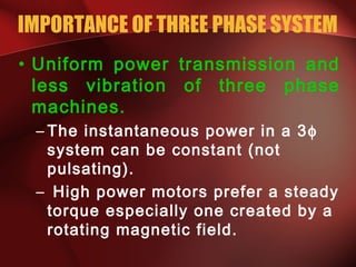
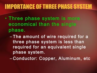
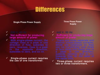
1.1 Three phase power
supply
P. Maria Sheeba
AP/ECE
MZCET
IMPORTANCE OF THREE PHASE SYSTEM
• Uniform power transmission and
less vibration of three phase
machines.
– The instantaneous power in a 3φ
system can be constant (not
pulsating).
– High power motors prefer a steady
torque especially one created by a
rotating magnetic field.
IMPORTANCE OF THREE PHASE SYSTEM
• Three phase system is more
economical than the single
phase.
– The amount of wire required for a
three phase system is less than
required for an equivalent single
phase system.
– Conductor: Copper, Aluminum, etc
Differences
Single Phase Power Supply
 230 V, 50 Hz
 Not sufficient for producing
large amount of power.
 With single-phase current, the
voltage rises to a peak in one
direction of flow, subsides to
zero, reverses, rises to a peak
in the opposite direction,
subsides to zero, and so on.
 Single-phase current requires
the use of one transformer.
Three Phase Power
Supply
 440 V, 50 Hz
 Sufficient for producing large
amount of power.
 There are three separate and
distinct single-phase currents,
which are combined so they
can be transmitted over three
or four wires and these rise to
a peak in one direction,
subside, reverse, and so on;
however they do not peak at
the same time.
 Three-phase current requires
two or three transformers.
Three Phase CirCuiTs
1.1.1 Introduction:
• The generator , motor , transformer or rectifier have only one
winding is called a single phase system
• If the current or voltage follows a phase difference 900
in a two
windings, called two phase systems
• If the phase difference is 1200
between voltages or currents in a
three winding, called as Three phase systems
• In poly-phase systems , there are more than three windings
Advantages of three phase system:
• More efficient than single phase system
• Cost is less
• Size is small . Compared to single phase system
Advantages of Three Phase Circuits
• The amount of conductor material is required less for transmitting
same power, over the same distance , under same power loss
• Three phase motors produce uniform torque , where as torque
produced by single motor is pulsating
• Three phase generators not produce the harmonics when they are
connected in parallel
• Three phase motors are self starting whereas single phase motors are
not self starting
THREE PHASE GENERATION
FARADAYS LAW
• Three things must be present
in order to produce electrical
current:
a) Magnetic field
b) Conductor
c) Relative motion
• Conductor cuts lines of
magnetic flux, a voltage is
induced in the conductor
• Direction and Speed are
GENERATING A SINGLE PHASE
Motion is parallel to the flux.
No voltage is induced.
N
S
x
N
S
Motion is 45° to flux.
Induced voltage is 0.707 of maximum.
GENERATING A SINGLE PHASE
x
N
S
Motion is perpendicular to flux.
Induced voltage is maximum.
GENERATING A SINGLE PHASE
Motion is 45° to flux.
x
N
S
Induced voltage is 0.707 of maximum.
GENERATING A SINGLE PHASE
N
S
Motion is parallel to flux.
No voltage is induced.
GENERATING A SINGLE PHASE
x
N
S
Notice current in the
conductor has reversed.
Induced voltage is
0.707 of maximum.
Motion is 45° to flux.
GENERATING A SINGLE PHASE
N
S
x
Motion is perpendicular to flux.
Induced voltage is maximum.
GENERATING A SINGLE PHASE
N
S
x
Motion is 45° to flux.
Induced voltage is 0.707 of maximum.
GENERATING A SINGLE PHASE
Motion is parallel to flux.
N
S
No voltage is induced.
Ready to produce another cycle.
THREE PHASE GENERATOR
GENERATOR WORK
• The generator consists of a
rotating magnet (rotor)
surrounded by a stationary
winding (stator).
• Three separate windings or
coils with terminals a-a’, b-b’,
and c-c’ are physically placed
120° apart around the stator.
• As the rotor rotates, its
magnetic field cuts the flux from
the three coils and induces
voltages in the coils.
• The induced voltage have equal
magnitude but out of phase by
120°.
GENERATION OF THREE-PHASE AC
N
xx
S
1.1.2 Generation of Three Phase Voltages
BALANCED 3φ VOLTAGES
• Balanced three phase voltages:
– same magnitude (VM )
– 120° phase shift
( )
( )
( ) ( )°+=°−=
°−=
=
120cos240cos)(
120cos)(
cos)(
tVtVtv
tVtv
tVtv
MMcn
Mbn
Man
ωω
ω
ω
• Vectorially r.m.s values of voltages
induced in three windings are represented
in the diagram
• ER = E ∟0o
v,
• EY = E ∟-120o
v
• EB= E ∟+120o
v
 Three voltages are not in phase, since there is a
phase difference of
 The order of voltage waveform sequences in a
polyphase system is called phase
rotation or phase sequence.
 This sequence of phase shifts has a definite
order. For clockwise rotation, the order is 1-2-3
(i.e) RYB (winding 1 peaks first, them winding 2,
then winding 3), which is known as a positive
phase sequence.
MZCET
1.1.3 PHASE SEQUENCE

120
PHASE SEQUENCE
 For anti-clockwise rotation,
the order is 3-2-1 (i.e) RBY
(winding 3 peaks first, them
winding 2, then winding 1),
which is known as a
negative phase sequence.
 If we’re using a polyphase
voltage source to power
resistive loads, phase
rotation will make no
difference at all.
 Whether 1-2-3 or 3-2-1, the
voltage and current
magnitudes will all be the
same. 
PHASE SEQUENCE
( )
( )°+=
°−=
=
120cos)(
120cos)(
cos)(
tVtv
tVtv
tVtv
Mcn
Mbn
Man
ω
ω
ω
°+∠=
°−∠=
°∠=
120
120
0
Mcn
Mbn
Man
VV
VV
VV
POSITIVE
SEQUENCE
NEGATIVE
SEQUENCE
°−∠=
°+∠=
°∠=
120
120
0
Mcn
Mbn
Man
VV
VV
VV
Overview of Three phase power supply
 Both single phase and three phase power systems
refer to units using alternating current (AC) electric
power. With AC power, the flow of current is
constantly alternating directions.
 The primary difference between single phase and
three phase AC power is the constancy of delivery.

1.1 three phase power supply

  • 1.
    1.1 Three phasepower supply P. Maria Sheeba AP/ECE MZCET
  • 2.
    IMPORTANCE OF THREEPHASE SYSTEM • Uniform power transmission and less vibration of three phase machines. – The instantaneous power in a 3φ system can be constant (not pulsating). – High power motors prefer a steady torque especially one created by a rotating magnetic field.
  • 3.
    IMPORTANCE OF THREEPHASE SYSTEM • Three phase system is more economical than the single phase. – The amount of wire required for a three phase system is less than required for an equivalent single phase system. – Conductor: Copper, Aluminum, etc
  • 4.
    Differences Single Phase PowerSupply  230 V, 50 Hz  Not sufficient for producing large amount of power.  With single-phase current, the voltage rises to a peak in one direction of flow, subsides to zero, reverses, rises to a peak in the opposite direction, subsides to zero, and so on.  Single-phase current requires the use of one transformer. Three Phase Power Supply  440 V, 50 Hz  Sufficient for producing large amount of power.  There are three separate and distinct single-phase currents, which are combined so they can be transmitted over three or four wires and these rise to a peak in one direction, subside, reverse, and so on; however they do not peak at the same time.  Three-phase current requires two or three transformers.
  • 5.
  • 6.
    1.1.1 Introduction: • Thegenerator , motor , transformer or rectifier have only one winding is called a single phase system • If the current or voltage follows a phase difference 900 in a two windings, called two phase systems • If the phase difference is 1200 between voltages or currents in a three winding, called as Three phase systems • In poly-phase systems , there are more than three windings Advantages of three phase system: • More efficient than single phase system • Cost is less • Size is small . Compared to single phase system
  • 7.
    Advantages of ThreePhase Circuits • The amount of conductor material is required less for transmitting same power, over the same distance , under same power loss • Three phase motors produce uniform torque , where as torque produced by single motor is pulsating • Three phase generators not produce the harmonics when they are connected in parallel • Three phase motors are self starting whereas single phase motors are not self starting
  • 8.
  • 9.
    FARADAYS LAW • Threethings must be present in order to produce electrical current: a) Magnetic field b) Conductor c) Relative motion • Conductor cuts lines of magnetic flux, a voltage is induced in the conductor • Direction and Speed are
  • 10.
    GENERATING A SINGLEPHASE Motion is parallel to the flux. No voltage is induced. N S
  • 11.
    x N S Motion is 45°to flux. Induced voltage is 0.707 of maximum. GENERATING A SINGLE PHASE
  • 12.
    GENERATING A SINGLEPHASE x N S Motion is perpendicular to flux. Induced voltage is maximum.
  • 13.
    GENERATING A SINGLEPHASE Motion is 45° to flux. x N S Induced voltage is 0.707 of maximum.
  • 14.
    GENERATING A SINGLEPHASE N S Motion is parallel to flux. No voltage is induced.
  • 15.
    GENERATING A SINGLEPHASE x N S Notice current in the conductor has reversed. Induced voltage is 0.707 of maximum. Motion is 45° to flux.
  • 16.
    GENERATING A SINGLEPHASE N S x Motion is perpendicular to flux. Induced voltage is maximum.
  • 17.
    GENERATING A SINGLEPHASE N S x Motion is 45° to flux. Induced voltage is 0.707 of maximum.
  • 18.
    GENERATING A SINGLEPHASE Motion is parallel to flux. N S No voltage is induced. Ready to produce another cycle.
  • 19.
  • 20.
    GENERATOR WORK • Thegenerator consists of a rotating magnet (rotor) surrounded by a stationary winding (stator). • Three separate windings or coils with terminals a-a’, b-b’, and c-c’ are physically placed 120° apart around the stator.
  • 21.
    • As therotor rotates, its magnetic field cuts the flux from the three coils and induces voltages in the coils. • The induced voltage have equal magnitude but out of phase by 120°.
  • 22.
  • 23.
    1.1.2 Generation ofThree Phase Voltages
  • 24.
    BALANCED 3φ VOLTAGES •Balanced three phase voltages: – same magnitude (VM ) – 120° phase shift ( ) ( ) ( ) ( )°+=°−= °−= = 120cos240cos)( 120cos)( cos)( tVtVtv tVtv tVtv MMcn Mbn Man ωω ω ω
  • 25.
    • Vectorially r.m.svalues of voltages induced in three windings are represented in the diagram • ER = E ∟0o v, • EY = E ∟-120o v • EB= E ∟+120o v
  • 26.
     Three voltagesare not in phase, since there is a phase difference of  The order of voltage waveform sequences in a polyphase system is called phase rotation or phase sequence.  This sequence of phase shifts has a definite order. For clockwise rotation, the order is 1-2-3 (i.e) RYB (winding 1 peaks first, them winding 2, then winding 3), which is known as a positive phase sequence. MZCET 1.1.3 PHASE SEQUENCE  120
  • 27.
  • 28.
     For anti-clockwiserotation, the order is 3-2-1 (i.e) RBY (winding 3 peaks first, them winding 2, then winding 1), which is known as a negative phase sequence.  If we’re using a polyphase voltage source to power resistive loads, phase rotation will make no difference at all.  Whether 1-2-3 or 3-2-1, the voltage and current magnitudes will all be the same. 
  • 29.
    PHASE SEQUENCE ( ) ()°+= °−= = 120cos)( 120cos)( cos)( tVtv tVtv tVtv Mcn Mbn Man ω ω ω °+∠= °−∠= °∠= 120 120 0 Mcn Mbn Man VV VV VV POSITIVE SEQUENCE NEGATIVE SEQUENCE °−∠= °+∠= °∠= 120 120 0 Mcn Mbn Man VV VV VV
  • 30.
    Overview of Threephase power supply  Both single phase and three phase power systems refer to units using alternating current (AC) electric power. With AC power, the flow of current is constantly alternating directions.  The primary difference between single phase and three phase AC power is the constancy of delivery.