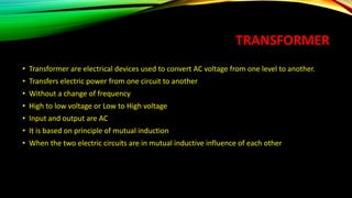
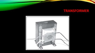
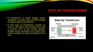
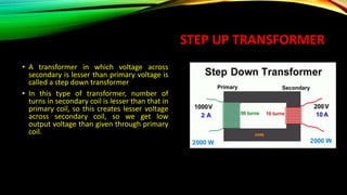
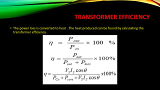
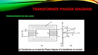
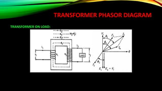
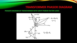
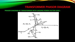
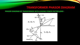
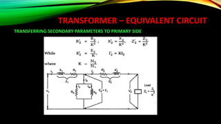
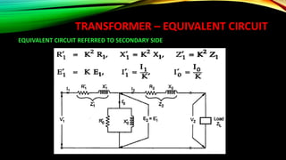
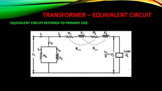
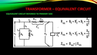
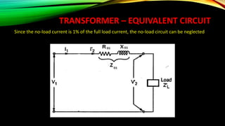
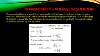
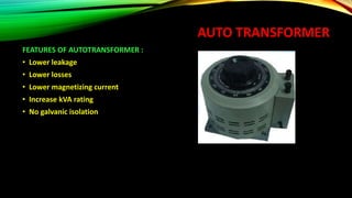
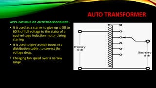
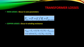
TRANFORMER
UNIT 2
CONTENT
• OPERATION
• TYPES & CONSTRUCTION
• EMF EQUATION
• PHASOR DIAGRAM
• EQUIVALENT CIRCUIT
• REGULATION
• EFFICIENCY
• AUTO-TRANSFORMER
TRANSFORMER
• Transformer are electrical devices used to convert AC voltage from one level to another.
• Transfers electric power from one circuit to another
• Without a change of frequency
• High to low voltage or Low to High voltage
• Input and output are AC
• It is based on principle of mutual induction
• When the two electric circuits are in mutual inductive influence of each other
TRANSFORMER
TRANSFORMER
TRANSFORMER
TRANSFORMER
A TRANSFORMER CONSISTS OF 3 BASIC COMPONENTS
• PRIMARY COIL OR PRIMARY WINDING : It is an electrical wire wrapped around the core on
the input side
• SECONDARY COIL OR SECONDARY WINDING: It is an electrical wire wrapped around the
core on the output side
• CORE : A ferromagnetic material that can conduct a magnetic field through it. Example: Iron
TRANSFORMER STRUCTURE
TRANSFORMER CONSTRUCTION
SHELL TYPE : Windings are wrapped around the center leg of a laminated core.
TRANSFORMER CONSTRUCTION
SHELL TYPE : Windings are wrapped around the center leg of a laminated core.
TRANSFORMER CONSTRUCTION
CORE TYPE: Windings are wrapped around two sides of a laminated square core.
TRANSFORMER CONSTRUCTION
SECTIONAL VIEW OF TRANSFORMER
TRANSFORMER OPERATION
• An electrical transformer normally consists of a ferromagnetic core and two coils called
"windings".
• A transformer uses the principle of mutual inductance to create an AC voltage in the
secondary coil from the alternating electric current flowing through the primary coil.
• The voltage induced in the secondary can be used to drive a load.
• The transformer improves the efficiency of the transfer of energy from one coil to another
by using a core to concentrate the magnetic field.
• The primary coil creates a magnetic field that is concentrated by the core and induces a
voltage in the secondary coil
TRANSFORMER OPERATION
MUTUAL INDUCTANCE
• The principle of mutual inductance
says that when two electrical coils are
placed near to each other, AC electrical
current flowing in one coil induces an
AC voltage in the other coil.
• This is because current in the first coil
creates a magnetic field around the
first coil which in turn induces a
voltage in second coil
TRANSFORMER
TURNS RATIO
• The voltage at the secondary coil can
be different from the voltage at the
primary. This happens when the
number of turns of the coil in primary
and secondary are not the same
• The Turns Ratio (TR) is the ratio of the
number of turns in the primary coil to
the number of turns in the secondary
coil
TRANSFORMER FORMULA
• TR= Vp / Vs
• Also TR= Np /Ns
• So we can say
Vp / Vs = Np /Ns
Also Vp/Vs=Is /Ip
TRANSFORMER
INPUT POWER AND OUTPUT POWER OF A TRANSFORMER :
• Under ideal conditions input power and output power should be the same. But there is
power loss between the primary and secondary and so practically they are not exactly
equal.
• So, Pin = Pout + Ploss
TRANSFORMER EFFICIENCY
• The power loss is converted to heat . The heat produced can be found by calculating the
transformer efficiency.
TRANSFORMER TYPES
• ISOLATION TRANSFORMER : In isolation transformer, the primary and secondary are
physically isolated (no electrical connection)
• AUTO TRANSFORMER : An autotransformer uses only one coil for the primary and
secondary. It uses taps on the coil to produce the different ratios and voltages.
TRANSFORMER TYPES
• Step up/Unit transformers – located at output of a generator to step up the voltage level to
transmit the power
• Step down/Substation transformers – Located at main distribution or secondary level
transmission substations to lower the voltage levels for distribution 1st level purposes
• Distribution Transformers – located at small distribution substation. It lowers the voltage
levels for 2nd level distribution purposes.
• Special Purpose Transformers - E.g. Potential Transformer (PT) , Current Transformer (CT)
STEP UP TRANSFORMER
• A transformer in which voltage across
secondary is greater than primary voltage
is called a step up transformer.
• In this type of transformer, number of
turns in secondary coil is greater than that
in primary coil, so this creates greater
voltage across secondary coil to get more
output voltage than given through primary
coil.
STEP UP TRANSFORMER
• A transformer in which voltage across
secondary is lesser than primary voltage is
called a step down transformer
• In this type of transformer, number of
turns in secondary coil is lesser than that in
primary coil, so this creates lesser voltage
across secondary coil, so we get low
output voltage than given through primary
coil.
TRANSFORMER EFFICIENCY
• The power loss is converted to heat . The heat produced can be found by calculating the
transformer efficiency.
TRANSFORMER PHASOR DIAGRAM
TRANSFORMER ON NO-LOAD:
TRANSFORMER PHASOR DIAGRAM
TRANSFORMER ON LOAD:
TRANSFORMER PHASOR DIAGRAM
PHASOR DIAGRAM OF TRANSFORMER WITH UNITY POWER FACTOR LOAD :
TRANSFORMER PHASOR DIAGRAM
PHASOR DIAGRAM OF TRANSFORMER WITH LAGGING POWER FACTOR LOAD :
TRANSFORMER PHASOR DIAGRAM
PHASOR DIAGRAM OF TRANSFORMER WITH LEADING POWER FACTOR LOAD :
TRANSFORMER PHASOR DIAGRAM
TRANSFORMER – EQUIVALENT CIRCUIT
NO LOAD EQUIVALENT CIRCUIT :
TRANSFORMER – EQUIVALENT CIRCUIT
EQUIVALENT CIRCUIT PARAMETERS REFERRED TO PRIMARY AND SECONDARY SIDES
RESPECTIVELY
TRANSFORMER – EQUIVALENT CIRCUIT
• The effect of circuit parameters shouldn’t be changed while transferring the parameters
from one side to another side
• It can be proved that a resistance of R2 in sec. is equivalent to R2/k2 will be denoted as
R2’(ie. Equivalent sec. resistance w.r.t primary) which would have caused the same loss as R2
in secondary,
TRANSFORMER – EQUIVALENT CIRCUIT
TRANSFERRING SECONDARY PARAMETERS TO PRIMARY SIDE
TRANSFORMER – EQUIVALENT CIRCUIT
EQUIVALENT CIRCUIT REFERRED TO SECONDARY SIDE
TRANSFORMER – EQUIVALENT CIRCUIT
EQUIVALENT CIRCUIT REFERRED TO PRIMARY SIDE
TRANSFORMER – EQUIVALENT CIRCUIT
EQUIVALENT CIRCUIT REFERRED TO PRIMARY SIDE
TRANSFORMER – EQUIVALENT CIRCUIT
Since the no-load current is 1% of the full load current, the no-load circuit can be neglected
TRANSFORMER – EQUIVALENT CIRCUIT
Since the no-load current is 1% of the full load current, the no-load circuit can be neglected
TRANSFORMER – VOLTAGE REGULATION
The output voltage of a transformer varies with the load even if the input voltage remains
constant. This is because a real transformer has series impedance within it. Full load Voltage
Regulation is a quantity that compares the output voltage at no load with the output voltage
at full load, defined by this equation:
AUTO TRANSFORMER
• The autotransformer has only one winding. The winding is common to both the primary
and secondary one
• The working principle is same as that of normal transformer difference is that it has one
winding divided into primary and secondary
AUTO TRANSFORMER
FEATURES OF AUTOTRANSFORMER :
• Lower leakage
• Lower losses
• Lower magnetizing current
• Increase kVA rating
• No galvanic isolation
AUTO TRANSFORMER
APPLICATIONS OF AUTOTRANSFORMER :
• It is used as a starter to give up to 50 to
60 % of full voltage to the stator of a
squirrel cage induction motor during
starting
• It is used to give a small boost to a
distribution cable , to correct the
voltage drop.
• Changing fan speed over a narrow
range.
TRANSFORMER LOSSES
• IRON LOSSES : Occur in core parameters
• COPPER LOSSES : Occur in winding resistance
TRANSFORMER
APPLICATION AND USER :
• The transformer used in television and photocopy machines
• The transmission and distribution of alternating power is possible by transformer
• Simple camera flash uses fly back transformer
• Single and auto transformer are used couple in amplifier.

Transformer

  • 1.
  • 2.
    CONTENT • OPERATION • TYPES& CONSTRUCTION • EMF EQUATION • PHASOR DIAGRAM • EQUIVALENT CIRCUIT • REGULATION • EFFICIENCY • AUTO-TRANSFORMER
  • 3.
    TRANSFORMER • Transformer areelectrical devices used to convert AC voltage from one level to another. • Transfers electric power from one circuit to another • Without a change of frequency • High to low voltage or Low to High voltage • Input and output are AC • It is based on principle of mutual induction • When the two electric circuits are in mutual inductive influence of each other
  • 4.
  • 5.
  • 6.
  • 7.
    TRANSFORMER A TRANSFORMER CONSISTSOF 3 BASIC COMPONENTS • PRIMARY COIL OR PRIMARY WINDING : It is an electrical wire wrapped around the core on the input side • SECONDARY COIL OR SECONDARY WINDING: It is an electrical wire wrapped around the core on the output side • CORE : A ferromagnetic material that can conduct a magnetic field through it. Example: Iron
  • 8.
  • 9.
    TRANSFORMER CONSTRUCTION SHELL TYPE: Windings are wrapped around the center leg of a laminated core.
  • 10.
    TRANSFORMER CONSTRUCTION SHELL TYPE: Windings are wrapped around the center leg of a laminated core.
  • 11.
    TRANSFORMER CONSTRUCTION CORE TYPE:Windings are wrapped around two sides of a laminated square core.
  • 12.
  • 13.
    TRANSFORMER OPERATION • Anelectrical transformer normally consists of a ferromagnetic core and two coils called "windings". • A transformer uses the principle of mutual inductance to create an AC voltage in the secondary coil from the alternating electric current flowing through the primary coil. • The voltage induced in the secondary can be used to drive a load. • The transformer improves the efficiency of the transfer of energy from one coil to another by using a core to concentrate the magnetic field. • The primary coil creates a magnetic field that is concentrated by the core and induces a voltage in the secondary coil
  • 14.
  • 15.
    TRANSFORMER OPERATION MUTUAL INDUCTANCE •The principle of mutual inductance says that when two electrical coils are placed near to each other, AC electrical current flowing in one coil induces an AC voltage in the other coil. • This is because current in the first coil creates a magnetic field around the first coil which in turn induces a voltage in second coil
  • 16.
    TRANSFORMER TURNS RATIO • Thevoltage at the secondary coil can be different from the voltage at the primary. This happens when the number of turns of the coil in primary and secondary are not the same • The Turns Ratio (TR) is the ratio of the number of turns in the primary coil to the number of turns in the secondary coil
  • 17.
    TRANSFORMER FORMULA • TR=Vp / Vs • Also TR= Np /Ns • So we can say Vp / Vs = Np /Ns Also Vp/Vs=Is /Ip
  • 18.
    TRANSFORMER INPUT POWER ANDOUTPUT POWER OF A TRANSFORMER : • Under ideal conditions input power and output power should be the same. But there is power loss between the primary and secondary and so practically they are not exactly equal. • So, Pin = Pout + Ploss
  • 19.
    TRANSFORMER EFFICIENCY • Thepower loss is converted to heat . The heat produced can be found by calculating the transformer efficiency.
  • 20.
    TRANSFORMER TYPES • ISOLATIONTRANSFORMER : In isolation transformer, the primary and secondary are physically isolated (no electrical connection) • AUTO TRANSFORMER : An autotransformer uses only one coil for the primary and secondary. It uses taps on the coil to produce the different ratios and voltages.
  • 21.
    TRANSFORMER TYPES • Stepup/Unit transformers – located at output of a generator to step up the voltage level to transmit the power • Step down/Substation transformers – Located at main distribution or secondary level transmission substations to lower the voltage levels for distribution 1st level purposes • Distribution Transformers – located at small distribution substation. It lowers the voltage levels for 2nd level distribution purposes. • Special Purpose Transformers - E.g. Potential Transformer (PT) , Current Transformer (CT)
  • 22.
    STEP UP TRANSFORMER •A transformer in which voltage across secondary is greater than primary voltage is called a step up transformer. • In this type of transformer, number of turns in secondary coil is greater than that in primary coil, so this creates greater voltage across secondary coil to get more output voltage than given through primary coil.
  • 23.
    STEP UP TRANSFORMER •A transformer in which voltage across secondary is lesser than primary voltage is called a step down transformer • In this type of transformer, number of turns in secondary coil is lesser than that in primary coil, so this creates lesser voltage across secondary coil, so we get low output voltage than given through primary coil.
  • 24.
    TRANSFORMER EFFICIENCY • Thepower loss is converted to heat . The heat produced can be found by calculating the transformer efficiency.
  • 25.
  • 26.
  • 27.
    TRANSFORMER PHASOR DIAGRAM PHASORDIAGRAM OF TRANSFORMER WITH UNITY POWER FACTOR LOAD :
  • 28.
    TRANSFORMER PHASOR DIAGRAM PHASORDIAGRAM OF TRANSFORMER WITH LAGGING POWER FACTOR LOAD :
  • 29.
    TRANSFORMER PHASOR DIAGRAM PHASORDIAGRAM OF TRANSFORMER WITH LEADING POWER FACTOR LOAD :
  • 30.
  • 31.
    TRANSFORMER – EQUIVALENTCIRCUIT NO LOAD EQUIVALENT CIRCUIT :
  • 32.
    TRANSFORMER – EQUIVALENTCIRCUIT EQUIVALENT CIRCUIT PARAMETERS REFERRED TO PRIMARY AND SECONDARY SIDES RESPECTIVELY
  • 33.
    TRANSFORMER – EQUIVALENTCIRCUIT • The effect of circuit parameters shouldn’t be changed while transferring the parameters from one side to another side • It can be proved that a resistance of R2 in sec. is equivalent to R2/k2 will be denoted as R2’(ie. Equivalent sec. resistance w.r.t primary) which would have caused the same loss as R2 in secondary,
  • 34.
    TRANSFORMER – EQUIVALENTCIRCUIT TRANSFERRING SECONDARY PARAMETERS TO PRIMARY SIDE
  • 35.
    TRANSFORMER – EQUIVALENTCIRCUIT EQUIVALENT CIRCUIT REFERRED TO SECONDARY SIDE
  • 36.
    TRANSFORMER – EQUIVALENTCIRCUIT EQUIVALENT CIRCUIT REFERRED TO PRIMARY SIDE
  • 37.
    TRANSFORMER – EQUIVALENTCIRCUIT EQUIVALENT CIRCUIT REFERRED TO PRIMARY SIDE
  • 38.
    TRANSFORMER – EQUIVALENTCIRCUIT Since the no-load current is 1% of the full load current, the no-load circuit can be neglected
  • 39.
    TRANSFORMER – EQUIVALENTCIRCUIT Since the no-load current is 1% of the full load current, the no-load circuit can be neglected
  • 40.
    TRANSFORMER – VOLTAGEREGULATION The output voltage of a transformer varies with the load even if the input voltage remains constant. This is because a real transformer has series impedance within it. Full load Voltage Regulation is a quantity that compares the output voltage at no load with the output voltage at full load, defined by this equation:
  • 41.
    AUTO TRANSFORMER • Theautotransformer has only one winding. The winding is common to both the primary and secondary one • The working principle is same as that of normal transformer difference is that it has one winding divided into primary and secondary
  • 42.
    AUTO TRANSFORMER FEATURES OFAUTOTRANSFORMER : • Lower leakage • Lower losses • Lower magnetizing current • Increase kVA rating • No galvanic isolation
  • 43.
    AUTO TRANSFORMER APPLICATIONS OFAUTOTRANSFORMER : • It is used as a starter to give up to 50 to 60 % of full voltage to the stator of a squirrel cage induction motor during starting • It is used to give a small boost to a distribution cable , to correct the voltage drop. • Changing fan speed over a narrow range.
  • 44.
    TRANSFORMER LOSSES • IRONLOSSES : Occur in core parameters • COPPER LOSSES : Occur in winding resistance
  • 45.
    TRANSFORMER APPLICATION AND USER: • The transformer used in television and photocopy machines • The transmission and distribution of alternating power is possible by transformer • Simple camera flash uses fly back transformer • Single and auto transformer are used couple in amplifier.