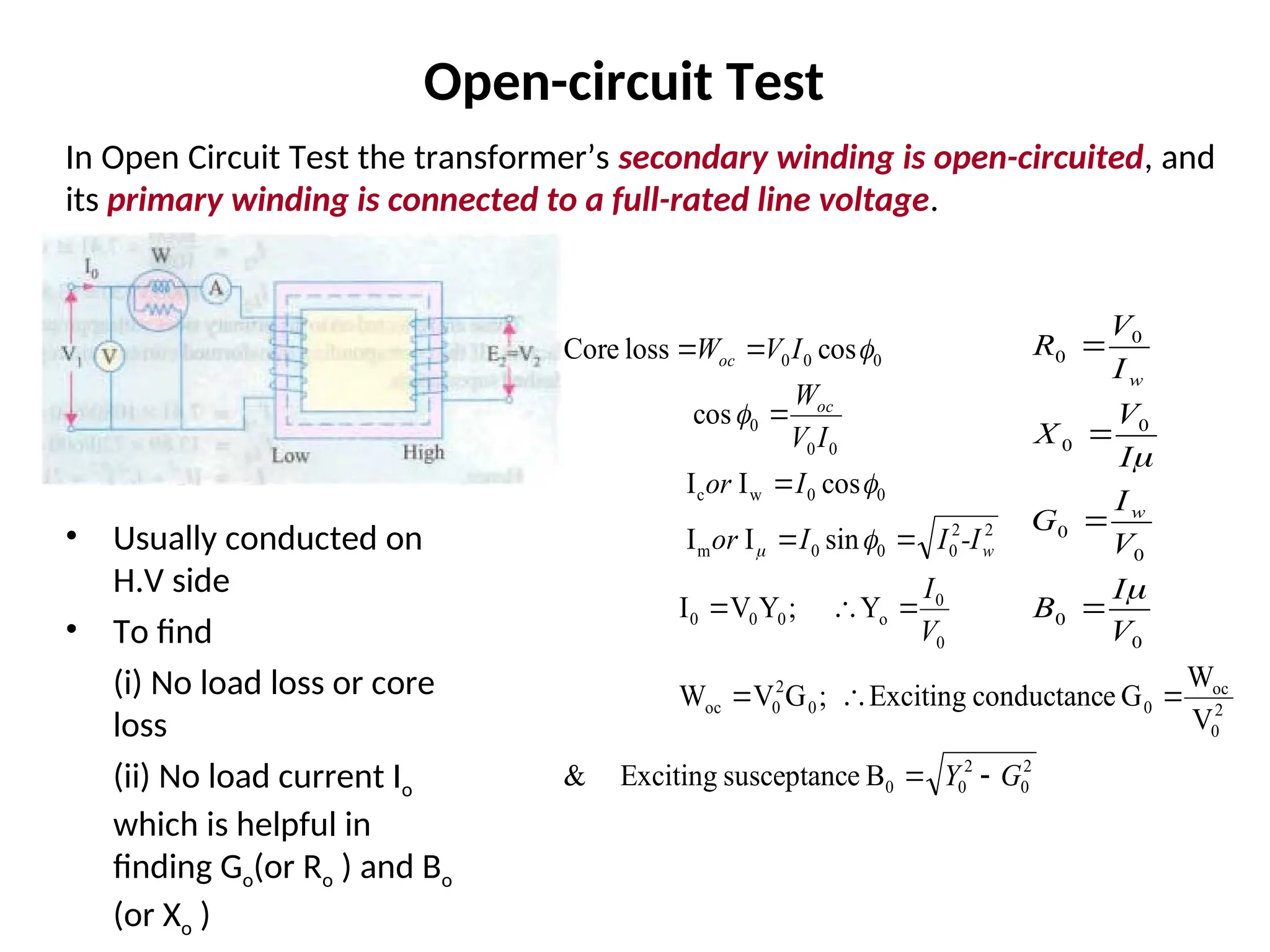
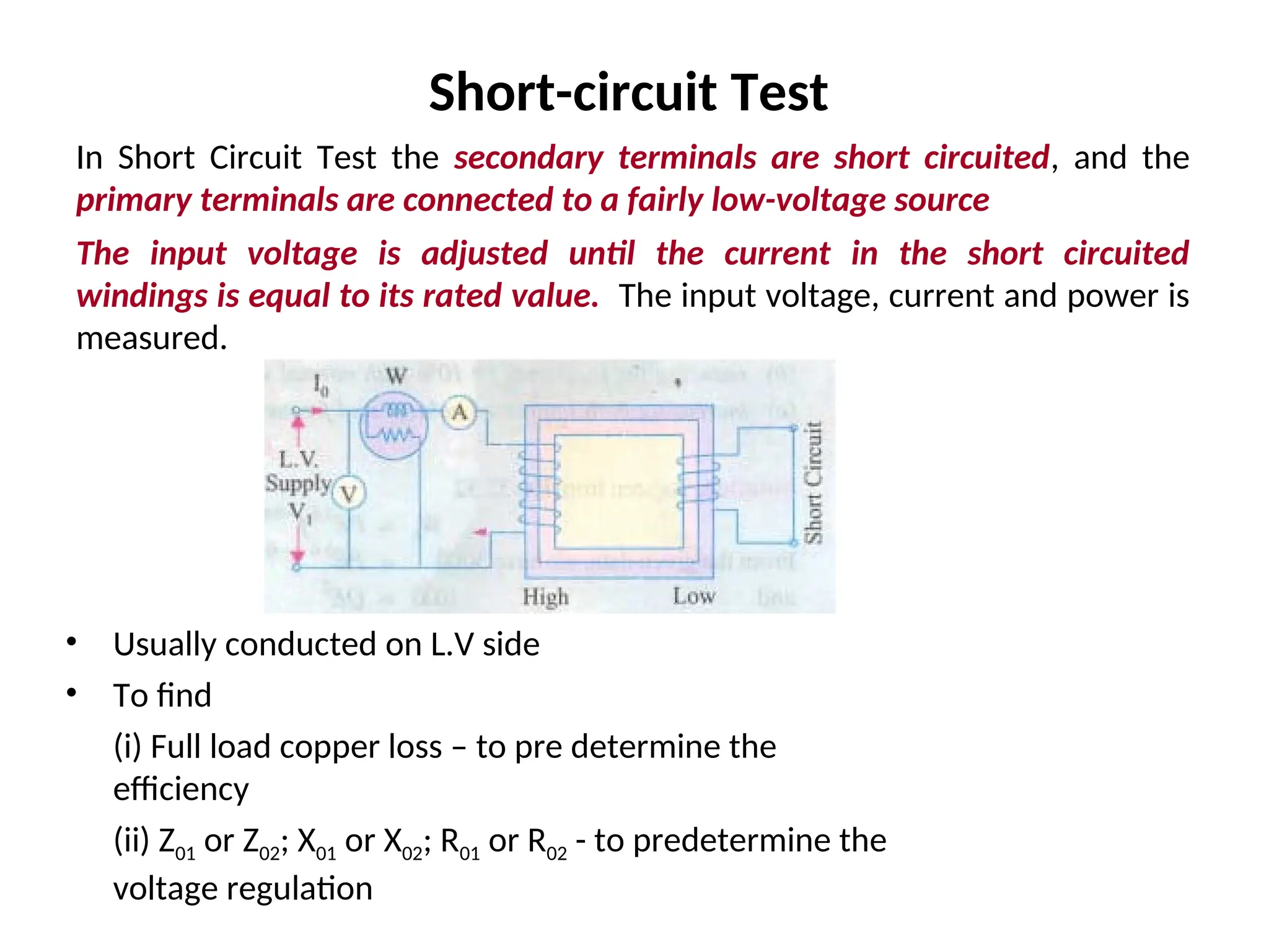
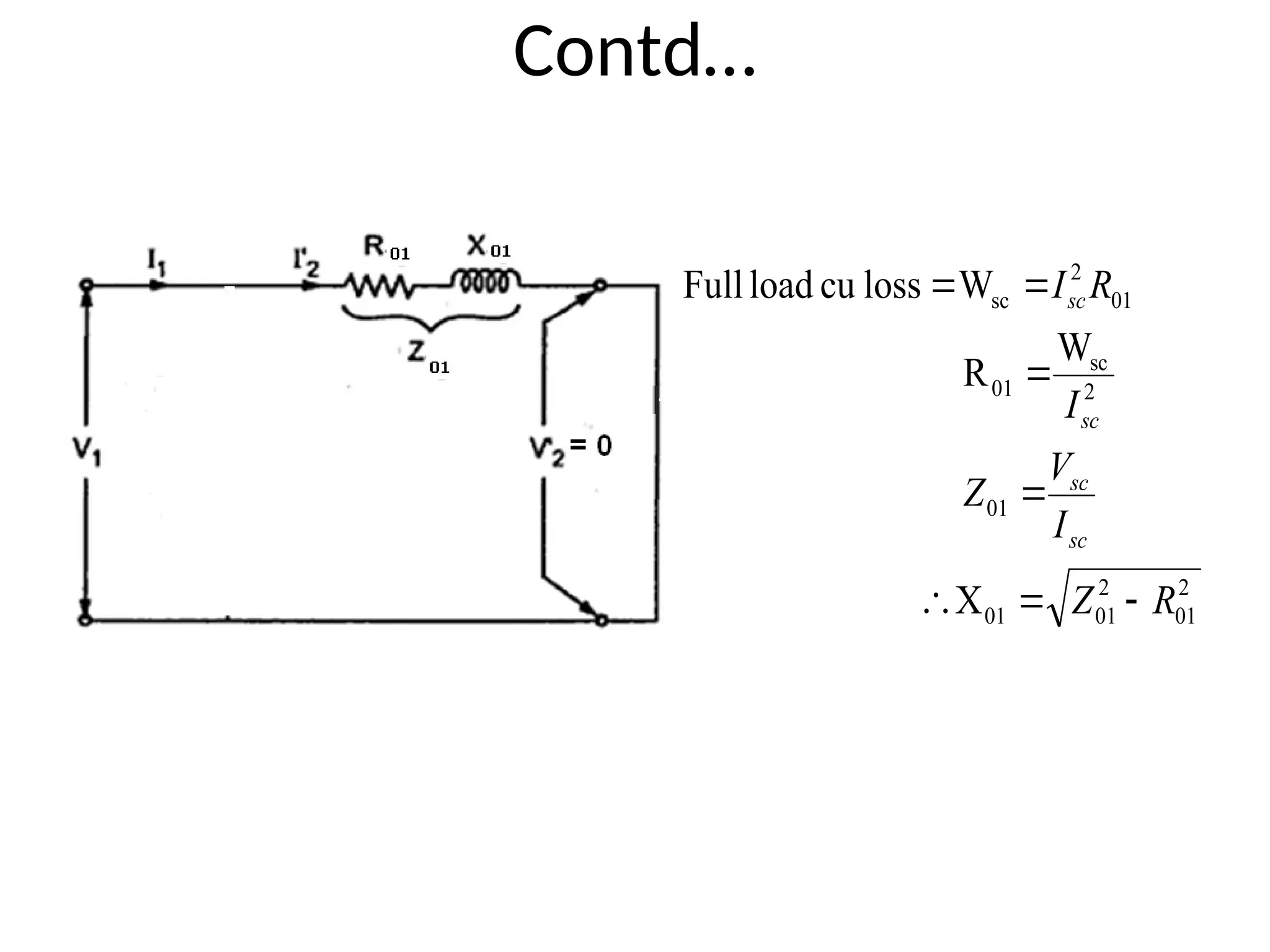
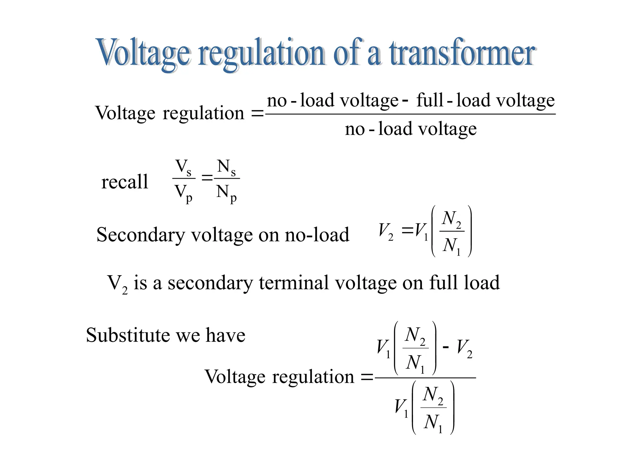
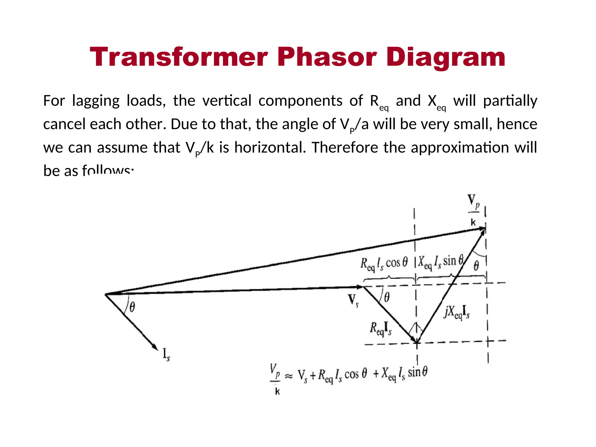
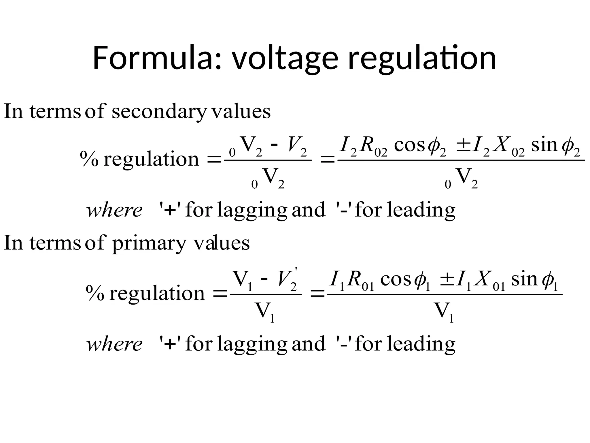
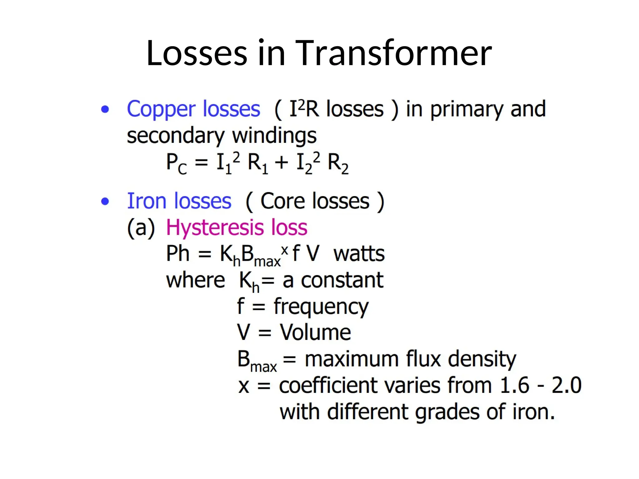
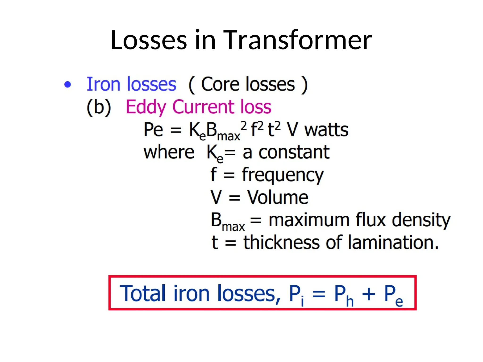
Unit 1
Transformers
Transformer
An A.C. device used to change high voltage low
current A.C. into low voltage high current A.C. and
vice-versa without changing the frequency
In brief,
1. Transfers electric power from one circuit to another
2. It does so without a change of frequency
3. It accomplishes this by electromagnetic induction
4. Where the two electric circuits are in mutual
inductive influence of each other.
Principle of operation
It is based on
principle of MUTUAL
INDUCTION.
According to which
an e.m.f. is induced
in a coil when
current in the
neighbouring coil
changes.
Constructional detail : Shell type
• Windings are wrapped around the center leg of a
laminated core.
Core type
• Windings are wrapped around two sides of a laminated square
core.
Sectional view of transformers
Note:
High voltage conductors are smaller cross section conductors
than the low voltage coils
Construction of transformer from
stampings
Core type
Fig1: Coil and laminations of
core type transformer
Fig2: Various types of cores
Shell type
• The HV and LV
windings are split
into no. of sections
• Where HV winding
lies between two LV
windings
• In sandwich coils
leakage can be
controlled
Fig: Sandwich windings
Cut view of transformer
Transformer with conservator and
breather
Working of a transformer
1. When current in the primary coil
changes being alternating in
nature, a changing magnetic field
is produced
2. This changing magnetic field gets
associated with the secondary
through the soft iron core
3. Hence magnetic flux linked with
the secondary coil changes.
4. Which induces e.m.f. in the
secondary.
Ideal Transformers
• Zero leakage flux:
-Fluxes produced by the primary and secondary
currents are confined within the core
• The windings have no resistance:
- Induced voltages equal applied voltages
• The core has infinite permeability
- Reluctance of the core is zero
- Negligible current is required to establish magnetic
flux
• Loss-less magnetic core
- No hysteresis or eddy currents
Ideal transformer
V1 – supply voltage ; I1- noload input current ;
V2- output voltgae; I2- output current
Im- magnetising current;
E1-self induced emf ; E2- mutually induced emf
Phasor diagram: Transformer on No-
load
Transformer on load assuming no
voltage drop in the winding
Fig shows the Phasor diagram of a
transformer on load by assuming
1.No voltage drop in the winding
2.Equal no. of primary and secondary turns
Transformer on load
Fig. a: Ideal transformer on load
Fig. b: Main flux and leakage
flux in a transformer
Phasor diagram of transformer with
UPF load
Phasor diagram of transformer with
lagging p.f load
Phasor diagram of transformer with
leading p.f load
Equivalent circuit of a transformer
No load equivalent circuit:
Equivalent circuit parameters referred to
primary and secondary sides respectively
Contd.,
• The effect of circuit parameters shouldn’t be changed while
transferring the parameters from one side to another side
• It can be proved that a resistance of R2 in sec. is equivalent to
R2/k2
will be denoted as R2’(ie. Equivalent sec. resistance w.r.t
primary) which would have caused the same loss as R2 in
secondary,
2
2
2
2
1
2
'
2
2
2
2
'
2
2
1
k
R
R











R
I
I
R
I
R
I
Transferring secondary parameters to
primary side
Equivalent circuit referred to
secondary side
•Transferring primary side parameters to secondary side
Similarly exciting circuit parameters are also transferred to
secondary as Ro’ and Xo’
equivalent circuit w.r.t primary
where
Approximate equivalent circuit
• Since the noload current is 1% of the full load
current, the nolad circuit can be neglected
Transformer Tests
Electrical Machines
•The performance of a transformer can be calculated on the basis of
equivalent circuit
•The four main parameters of equivalent circuit are:
- R01 as referred to primary (or secondary R02)
- the equivalent leakage reactance X01 as referred to primary
(or secondary X02)
- Magnetising susceptance B0 ( or reactance X0)
- core loss conductance G0 (or resistance R0)
•The above constants can be easily determined by two tests
- Oper circuit test (O.C test / No load test)
- Short circuit test (S.C test/Impedance test)
•These tests are economical and convenient
- these tests furnish the result without actually loading the
transformer
In Open Circuit Test the transformer’s secondary winding is open-circuited, and
its primary winding is connected to a full-rated line voltage.
• Usually conducted on
H.V side
• To find
(i) No load loss or core
loss
(ii) No load current Io
which is helpful in
finding Go(or Ro ) and Bo
(or Xo )
2
0
2
0
0
2
0
oc
0
0
2
0
oc
0
0
o
0
0
0
2
2
0
0
0
m
0
0
w
c
0
0
0
0
0
0
B
e
susceptanc
Exciting
&
V
W
G
e
conductanc
Exciting
;
G
V
W
Y
;
Y
V
I
sin
I
I
cos
I
I
cos
cos
loss
Core
G
Y
V
I
-I
I
I
or
I
or
I
V
W
I
V
W
w
oc
oc



















Open-circuit Test
0
0
0
0
0
0
0
0
V
I
B
V
I
G
I
V
X
I
V
R
w
w






Short-circuit Test
In Short Circuit Test the secondary terminals are short circuited, and the
primary terminals are connected to a fairly low-voltage source
The input voltage is adjusted until the current in the short circuited
windings is equal to its rated value. The input voltage, current and power is
measured.
• Usually conducted on L.V side
• To find
(i) Full load copper loss – to pre determine the
efficiency
(ii) Z01 or Z02; X01 or X02; R01 or R02 - to predetermine the
voltage regulation
Contd…
2
01
2
01
01
01
2
sc
01
01
2
sc
X
W
R
W
loss
cu
load
Full
R
Z
I
V
Z
I
R
I
sc
sc
sc
sc







Transformer Voltage Regulation
and Efficiency
The output voltage of a transformer varies with the load even if the input
voltage remains constant. This is because a real transformer has series
impedance within it. Full load Voltage Regulation is a quantity that compares
the output voltage at no load with the output voltage at full load, defined by
this equation:
%
100
down
Regulation
%
100
up
Regulation
,
,
,
,
,
,






nl
S
fl
S
nl
S
fl
S
fl
S
nl
S
V
V
V
V
V
V  
 
%
100
/
down
Regulation
%
100
/
up
Regulation
V
V
k
noload
At
,
,
,
,
p
s
x
V
V
k
V
x
V
V
k
V
nl
S
fl
S
P
fl
S
fl
S
P





Ideal transformer, VR = 0%.
voltage
load
-
no
voltage
load
-
full
voltage
load
-
no
regulation
Voltage











1
2
1
2
N
N
V
V
p
s
p
s
N
N
V
V

recall
Secondary voltage on no-load
V2 is a secondary terminal voltage on full load


















1
2
1
2
1
2
1
regulation
Voltage
N
N
V
V
N
N
V
Substitute we have
Transformer Phasor Diagram
To determine the voltage regulation of a transformer, it is necessary
understand the voltage drops within it.
Transformer Phasor Diagram
Ignoring the excitation of the branch (since the current flow through the
branch is considered to be small), more consideration is given to the series
impedances (Req +jXeq).
Voltage Regulation depends on magnitude of the series impedance and the
phase angle of the current flowing through the transformer.
Phasor diagrams will determine the effects of these factors on the voltage
regulation. A phasor diagram consist of current and voltage vectors.
Assume that the reference phasor is the secondary voltage, VS. Therefore
the reference phasor will have 0 degrees in terms of angle.
Based upon the equivalent circuit, apply Kirchoff Voltage Law,
S
eq
S
eq
S
P
I
jX
I
R
V
k
V



Transformer Phasor Diagram
For lagging loads, VP / a > VS so the voltage regulation with lagging loads is > 0.
When the power factor is unity, VS is lower than VP so VR > 0.
Transformer Phasor Diagram
With a leading power factor, VS is higher than the referred VP so VR < 0
Transformer Phasor Diagram
For lagging loads, the vertical components of Req
and Xeq
will partially
cancel each other. Due to that, the angle of VP
/a will be very small, hence
we can assume that VP
/k is horizontal. Therefore the approximation will
be as follows:
Formula: voltage regulation
leading
for
'-'
and
lagging
for
'
'
V
sin
cos
V
V
regulation
%
lues
primary va
of
In terms
leading
for
'-'
and
lagging
for
'
'
V
sin
cos
V
V
regulation
%
values
secondary
of
In terms
1
1
01
1
1
01
1
1
'
2
1
2
0
2
02
2
2
02
2
2
0
2
2
0










where
X
I
R
I
V
where
X
I
R
I
V




Losses in Transformer
Transformer Efficiency
Three Phase Transformer
Advantages of Three Phase Transformer
Auto Transformer
Advantages of Auto Transformer
Disadvantages of Auto Transformer
Application of Auto Transformer
Harmonics in Transformer
Distortions in the voltage and current
waveforms of a transformer is known as
Harmonics.
Causes
•Core saturation: When a core or magnet loses
its magnetic strength due to thermal limits
•Fluctuating load: When the load on the
transformer changes
•Poor insulation: When the insulation around
the transformer is not good quality
•Mechanical vibrations: When the transformer
is subject to mechanical vibrations
Effects
•Increased heating
Harmonic currents cause additional losses in the
transformer's core and windings, which can lead to
overheating
•Insulation degradation
The insulation materials can degrade due to the higher
temperatures caused by harmonic currents
•Voltage distortion
Harmonic currents can distort the voltage, which can affect
the quality of power supplied to other appliances
•Reduced lifespan
The lifespan of the transformer can be reduced due to the
increased heating and insulation degradation
•Noise
Harmonics can introduce noise to the system

Unit 1 - Trfr.ppt transformer fundamental

  • 1.
  • 2.
    Transformer An A.C. deviceused to change high voltage low current A.C. into low voltage high current A.C. and vice-versa without changing the frequency In brief, 1. Transfers electric power from one circuit to another 2. It does so without a change of frequency 3. It accomplishes this by electromagnetic induction 4. Where the two electric circuits are in mutual inductive influence of each other.
  • 3.
    Principle of operation Itis based on principle of MUTUAL INDUCTION. According to which an e.m.f. is induced in a coil when current in the neighbouring coil changes.
  • 4.
    Constructional detail :Shell type • Windings are wrapped around the center leg of a laminated core.
  • 5.
    Core type • Windingsare wrapped around two sides of a laminated square core.
  • 6.
    Sectional view oftransformers Note: High voltage conductors are smaller cross section conductors than the low voltage coils
  • 7.
  • 8.
    Core type Fig1: Coiland laminations of core type transformer Fig2: Various types of cores
  • 9.
    Shell type • TheHV and LV windings are split into no. of sections • Where HV winding lies between two LV windings • In sandwich coils leakage can be controlled Fig: Sandwich windings
  • 10.
    Cut view oftransformer
  • 11.
  • 12.
    Working of atransformer 1. When current in the primary coil changes being alternating in nature, a changing magnetic field is produced 2. This changing magnetic field gets associated with the secondary through the soft iron core 3. Hence magnetic flux linked with the secondary coil changes. 4. Which induces e.m.f. in the secondary.
  • 14.
    Ideal Transformers • Zeroleakage flux: -Fluxes produced by the primary and secondary currents are confined within the core • The windings have no resistance: - Induced voltages equal applied voltages • The core has infinite permeability - Reluctance of the core is zero - Negligible current is required to establish magnetic flux • Loss-less magnetic core - No hysteresis or eddy currents
  • 15.
    Ideal transformer V1 –supply voltage ; I1- noload input current ; V2- output voltgae; I2- output current Im- magnetising current; E1-self induced emf ; E2- mutually induced emf
  • 18.
  • 19.
    Transformer on loadassuming no voltage drop in the winding Fig shows the Phasor diagram of a transformer on load by assuming 1.No voltage drop in the winding 2.Equal no. of primary and secondary turns
  • 20.
    Transformer on load Fig.a: Ideal transformer on load Fig. b: Main flux and leakage flux in a transformer
  • 21.
    Phasor diagram oftransformer with UPF load
  • 22.
    Phasor diagram oftransformer with lagging p.f load
  • 23.
    Phasor diagram oftransformer with leading p.f load
  • 24.
    Equivalent circuit ofa transformer No load equivalent circuit:
  • 25.
    Equivalent circuit parametersreferred to primary and secondary sides respectively
  • 26.
    Contd., • The effectof circuit parameters shouldn’t be changed while transferring the parameters from one side to another side • It can be proved that a resistance of R2 in sec. is equivalent to R2/k2 will be denoted as R2’(ie. Equivalent sec. resistance w.r.t primary) which would have caused the same loss as R2 in secondary, 2 2 2 2 1 2 ' 2 2 2 2 ' 2 2 1 k R R            R I I R I R I
  • 27.
  • 28.
    Equivalent circuit referredto secondary side •Transferring primary side parameters to secondary side Similarly exciting circuit parameters are also transferred to secondary as Ro’ and Xo’
  • 29.
  • 30.
    Approximate equivalent circuit •Since the noload current is 1% of the full load current, the nolad circuit can be neglected
  • 31.
    Transformer Tests Electrical Machines •Theperformance of a transformer can be calculated on the basis of equivalent circuit •The four main parameters of equivalent circuit are: - R01 as referred to primary (or secondary R02) - the equivalent leakage reactance X01 as referred to primary (or secondary X02) - Magnetising susceptance B0 ( or reactance X0) - core loss conductance G0 (or resistance R0) •The above constants can be easily determined by two tests - Oper circuit test (O.C test / No load test) - Short circuit test (S.C test/Impedance test) •These tests are economical and convenient - these tests furnish the result without actually loading the transformer
  • 32.
    In Open CircuitTest the transformer’s secondary winding is open-circuited, and its primary winding is connected to a full-rated line voltage. • Usually conducted on H.V side • To find (i) No load loss or core loss (ii) No load current Io which is helpful in finding Go(or Ro ) and Bo (or Xo ) 2 0 2 0 0 2 0 oc 0 0 2 0 oc 0 0 o 0 0 0 2 2 0 0 0 m 0 0 w c 0 0 0 0 0 0 B e susceptanc Exciting & V W G e conductanc Exciting ; G V W Y ; Y V I sin I I cos I I cos cos loss Core G Y V I -I I I or I or I V W I V W w oc oc                    Open-circuit Test 0 0 0 0 0 0 0 0 V I B V I G I V X I V R w w      
  • 33.
    Short-circuit Test In ShortCircuit Test the secondary terminals are short circuited, and the primary terminals are connected to a fairly low-voltage source The input voltage is adjusted until the current in the short circuited windings is equal to its rated value. The input voltage, current and power is measured. • Usually conducted on L.V side • To find (i) Full load copper loss – to pre determine the efficiency (ii) Z01 or Z02; X01 or X02; R01 or R02 - to predetermine the voltage regulation
  • 34.
  • 35.
    Transformer Voltage Regulation andEfficiency The output voltage of a transformer varies with the load even if the input voltage remains constant. This is because a real transformer has series impedance within it. Full load Voltage Regulation is a quantity that compares the output voltage at no load with the output voltage at full load, defined by this equation: % 100 down Regulation % 100 up Regulation , , , , , ,       nl S fl S nl S fl S fl S nl S V V V V V V     % 100 / down Regulation % 100 / up Regulation V V k noload At , , , , p s x V V k V x V V k V nl S fl S P fl S fl S P      Ideal transformer, VR = 0%.
  • 36.
    voltage load - no voltage load - full voltage load - no regulation Voltage            1 2 1 2 N N V V p s p s N N V V  recall Secondary voltage onno-load V2 is a secondary terminal voltage on full load                   1 2 1 2 1 2 1 regulation Voltage N N V V N N V Substitute we have
  • 37.
    Transformer Phasor Diagram Todetermine the voltage regulation of a transformer, it is necessary understand the voltage drops within it.
  • 38.
    Transformer Phasor Diagram Ignoringthe excitation of the branch (since the current flow through the branch is considered to be small), more consideration is given to the series impedances (Req +jXeq). Voltage Regulation depends on magnitude of the series impedance and the phase angle of the current flowing through the transformer. Phasor diagrams will determine the effects of these factors on the voltage regulation. A phasor diagram consist of current and voltage vectors. Assume that the reference phasor is the secondary voltage, VS. Therefore the reference phasor will have 0 degrees in terms of angle. Based upon the equivalent circuit, apply Kirchoff Voltage Law, S eq S eq S P I jX I R V k V   
  • 39.
    Transformer Phasor Diagram Forlagging loads, VP / a > VS so the voltage regulation with lagging loads is > 0. When the power factor is unity, VS is lower than VP so VR > 0.
  • 40.
    Transformer Phasor Diagram Witha leading power factor, VS is higher than the referred VP so VR < 0
  • 41.
    Transformer Phasor Diagram Forlagging loads, the vertical components of Req and Xeq will partially cancel each other. Due to that, the angle of VP /a will be very small, hence we can assume that VP /k is horizontal. Therefore the approximation will be as follows:
  • 42.
    Formula: voltage regulation leading for '-' and lagging for ' ' V sin cos V V regulation % lues primaryva of In terms leading for '-' and lagging for ' ' V sin cos V V regulation % values secondary of In terms 1 1 01 1 1 01 1 1 ' 2 1 2 0 2 02 2 2 02 2 2 0 2 2 0           where X I R I V where X I R I V    
  • 43.
  • 44.
  • 45.
  • 46.
  • 50.
    Advantages of ThreePhase Transformer
  • 51.
  • 53.
    Advantages of AutoTransformer
  • 54.
  • 55.
  • 56.
    Harmonics in Transformer Distortionsin the voltage and current waveforms of a transformer is known as Harmonics.
  • 57.
    Causes •Core saturation: Whena core or magnet loses its magnetic strength due to thermal limits •Fluctuating load: When the load on the transformer changes •Poor insulation: When the insulation around the transformer is not good quality •Mechanical vibrations: When the transformer is subject to mechanical vibrations
  • 58.
    Effects •Increased heating Harmonic currentscause additional losses in the transformer's core and windings, which can lead to overheating •Insulation degradation The insulation materials can degrade due to the higher temperatures caused by harmonic currents •Voltage distortion Harmonic currents can distort the voltage, which can affect the quality of power supplied to other appliances •Reduced lifespan The lifespan of the transformer can be reduced due to the increased heating and insulation degradation •Noise Harmonics can introduce noise to the system