Transformer its types ,working,basic principle.pptx
1.
TRANSFORMER
A transformer isa static electrical
device that transmits AC power from
one circuit to another at a constant
frequency, but the voltage level may be
changed, implying the voltage can be
increased or decreased depending on
the requirement.
2.
Types of Transformer
Transformertypes based on Voltage Level:
There are primarily two types of Transformer based on
the operating voltage.
3.
Step-down Transformer:
The primaryvoltage is converted to a lower
voltage across the secondary output using a step-
down transformer.
The number of windings on the primary side of a
step-down transformer is more than on the secondary
side. As a result, the overall secondary-to-primary
winding ratio will always be less than one.
Step-down transformer are used in electrical
systems that distribute electricity over long distances
and operate at extremely high voltages to ensure
minimum loss and economical solutions. Step-down
transformer are used to change high-voltage into low-
voltage supply lines.
4.
Step-up Transformer:
The secondaryvoltage of a step-up transformer is
raised from the low primary voltage.
Because the primary winding has fewer turns than the
secondary winding in this sort of transformer, the ratio of the
primary to secondary winding will be greater than one.
Step-up transformer are frequently used in electronics
stabilizers, inverters, and other devices that convert low
voltage to a significantly higher voltage. A step-up transformer
is also used in the distribution of electrical power. For
applications connected to power distribution, high voltage is
necessary. In the grid, a step-up transformer is used to raise
the voltage level prior to distribution.
5.
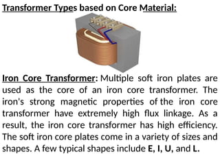
Transformer Types basedon Core Material:
Iron Core Transformer: Multiple soft iron plates are
used as the core of an iron core transformer. The
iron's strong magnetic properties of the iron core
transformer have extremely high flux linkage. As a
result, the iron core transformer has high efficiency.
The soft iron core plates come in a variety of sizes and
shapes. A few typical shapes include E, I, U, and L.
6.
Toroidal Core Transformer:
Ironcore or ferrite core are two examples of
toroid-shaped core materials used in transformer. For
their excellent electrical performance, toroids, which
have a ring- or donut-shaped core material, are
frequently used. The ring form results in very low
leakage inductance and extremely high inductance
7.
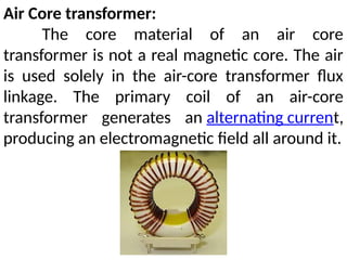
Air Core transformer:
Thecore material of an air core
transformer is not a real magnetic core. The air
is used solely in the air-core transformer flux
linkage. The primary coil of an air-core
transformer generates an alternating current,
producing an electromagnetic field all around it.
8.
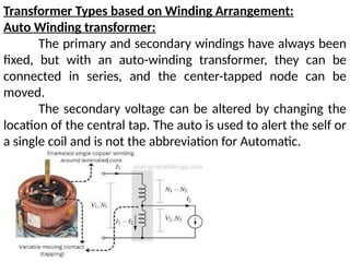
Transformer Types basedon Winding Arrangement:
Auto Winding transformer:
The primary and secondary windings have always been
fixed, but with an auto-winding transformer, they can be
connected in series, and the center-tapped node can be
moved.
The secondary voltage can be altered by changing the
location of the central tap. The auto is used to alert the self or
a single coil and is not the abbreviation for Automatic.
9.
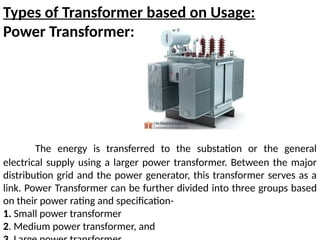
Types of Transformerbased on Usage:
Power Transformer:
The energy is transferred to the substation or the general
electrical supply using a larger power transformer. Between the major
distribution grid and the power generator, this transformer serves as a
link. Power Transformer can be further divided into three groups based
on their power rating and specification-
1. Small power transformer
2. Medium power transformer, and
10.
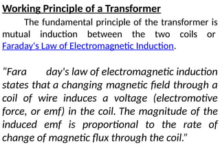
Working Principle ofa Transformer
The fundamental principle of the transformer is
mutual induction between the two coils or
Faraday's Law of Electromagnetic Induction.
“Fara day's law of electromagnetic induction
states that a changing magnetic field through a
coil of wire induces a voltage (electromotive
force, or emf) in the coil. The magnitude of the
induced emf is proportional to the rate of
change of magnetic flux through the coil.”
11.
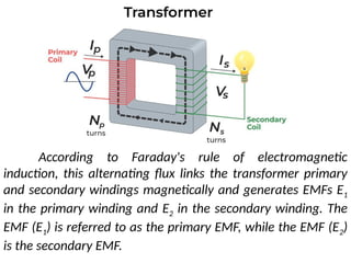
According to Faraday'srule of electromagnetic
induction, this alternating flux links the transformer primary
and secondary windings magnetically and generates EMFs E1
in the primary winding and E2 in the secondary winding. The
EMF (E1) is referred to as the primary EMF, while the EMF (E2)
is the secondary EMF.
12.
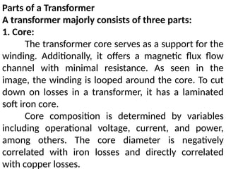
Parts of aTransformer
A transformer majorly consists of three parts:
1. Core:
The transformer core serves as a support for the
winding. Additionally, it offers a magnetic flux flow
channel with minimal resistance. As seen in the
image, the winding is looped around the core. To cut
down on losses in a transformer, it has a laminated
soft iron core.
Core composition is determined by variables
including operational voltage, current, and power,
among others. The core diameter is negatively
correlated with iron losses and directly correlated
with copper losses.
13.
2. Windings:
The copperwires that are wound over the transformer
core are known as windings. Copper cables are used because
Copper's high conductivity reduces transformer loss because
resistance to current flow lowers as conductivity rises. And
copper's high degree of ductility makes it possible to produce
incredibly thin wires out of it.
The two basic types of windings are. windings for the
primary and secondary coils. The primary winding is the group
of winding turns that receive supply current. The number of
winding turns from which output is derived is known as
secondary winding. Insulation coating agents are used to
insulate the primary and secondary windings from one
another.
14.
3. Insulation Agents:
Transformerrequire insulation to keep
the windings apart and prevent short
circuits. This makes mutual induction
easier. Transformer stability and durability
are influenced by insulation agents.
In a transformer, the following are
employed as insulating mediums:
Insulating fluid, tape, Paper, and
Lamination made of wood.
15.
4. Tank:
A transformermain tank serves
two purposes:
The core and the windings are
protected from the elements, such as
rain and dust.
It functions as an oil container as
well as a support for all other
transformer attachments.
16.
5. Transformer Oil:
Themajority of the huge
transformer are submerged in oil.
The transformer oil adds insulation
between the conductors, improves
heat dissipation from the coils, and has
fault-detecting capabilities.
Transformer oil is typically made of
hydrocarbon mineral oil.
17.
6. Oil Conservators:
Theoil conservator is situated above the
transformer tank and bushings. Some
transformer oil conservators contain a rubber
bladder. When a transformer is loaded, the
ambient temperature rises, causing the amount
of oil inside the transformer to increase.
The transformer conservator tank has
enough room for the increased transformer oil.
It also serves as a reservoir for oil that is used to
insulate buildings.
18.
7. Breather:
All oil-immersedtransformer with
conservator tank includes it.
It aids in the protection of the oil
against moisture.
19.
8. Radiators andFans:
The majority of the power lost in
the transformer is dissipated as heat.
Radiators and fans aid in the
dissipation of heat generated by the
transformer and provide protection
against failure. The majority of dry
transformer are cooled by natural air.
20.
Ideal Transformer
An idealtransformer is a purely
theoretical transformer that has no
losses at all, including no core
losses, copper losses, or other
transformer losses. This
transformer is thought to be 100%
efficient.
21.
Efficiency of Transformer
Theefficiency of a transformer is also
known as commercial efficiency. It is
represented by the letter ‘η’. The efficiency of a
Transformer is described as the ratio of output
(in W or kW) to input (in W or kW).
Hence, the efficiency of transformer may be
expressed as follows:
Efficiency (η) = (Power Output / Power Input)
22.
Energy Losses ina Transformer
Flux Leakage: Because some flux leaks from the core,
not all flux generated by the primary coil make it to the
secondary coil. This occurs as a result of the core's inadequate
design or the presence of air holes in the core. It is possible to
lower it by wrapping the primary and secondary coils over
each other. It can also be lowered if the core is well-designed.
Windings Resistance: Because the wire used for the
windings has some electrical resistance, energy is wasted as a
result of the heat generated in the windings. These are
mitigated in high current, low voltage windings by utilizing
thick wire with a high conductive substance.
23.
Eddy Currents:
The alternatingmagnetic flux creates eddy
currents in the iron core, resulting in energy
losses through heating. By using a laminated
core, the impact is decreased.
Hysteresis Loss:
In each AC cycle, the alternating magnetic
field reverses the magnetization of the core.
The loss of energy in the core occurs as heat
owing to hysteresis loss, which is minimized by
employing a magnetic material with a low
hysteresis loss.
24.
Application of Transformer
Increasingor reducing the voltage level in
an AC circuit to ensure the correct operation of
the circuit's various electrical components.
It stops DC from flowing from one circuit to
another.
It separates two separate electric circuits.
Before transmission and distribution can
take place, the voltage level at the electric
power plant must be increased.
25.
A transformer primarywinding is powered by a 120 V
ac source. If the turn ratio is 10, what does the secondary
voltage equal?
Given that, the turn ratio, N2/N1 = 10
And thevoltage across the primary coil, V1 = 120 V
Now, according to the transformer;'s equation:
V2/V1 = N2/N1
Substituting the given values,
V2/120 = 10
V2 = 1200 V