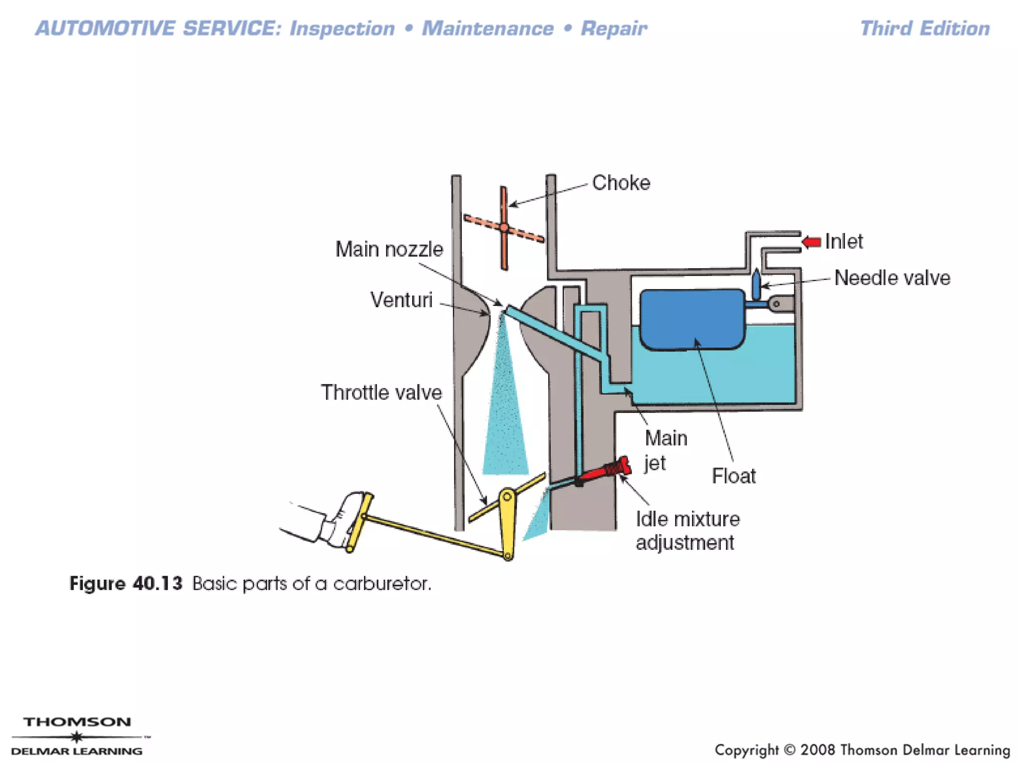
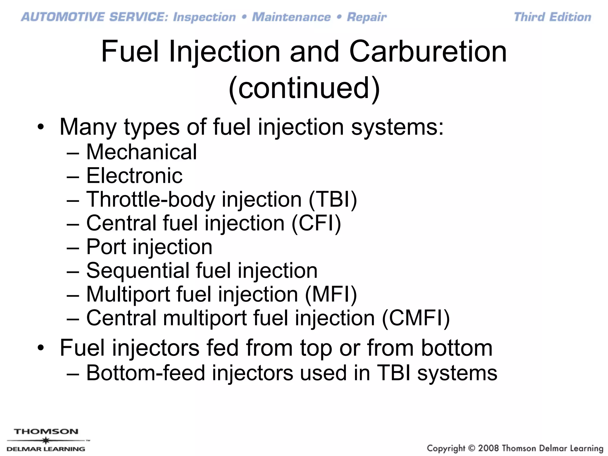
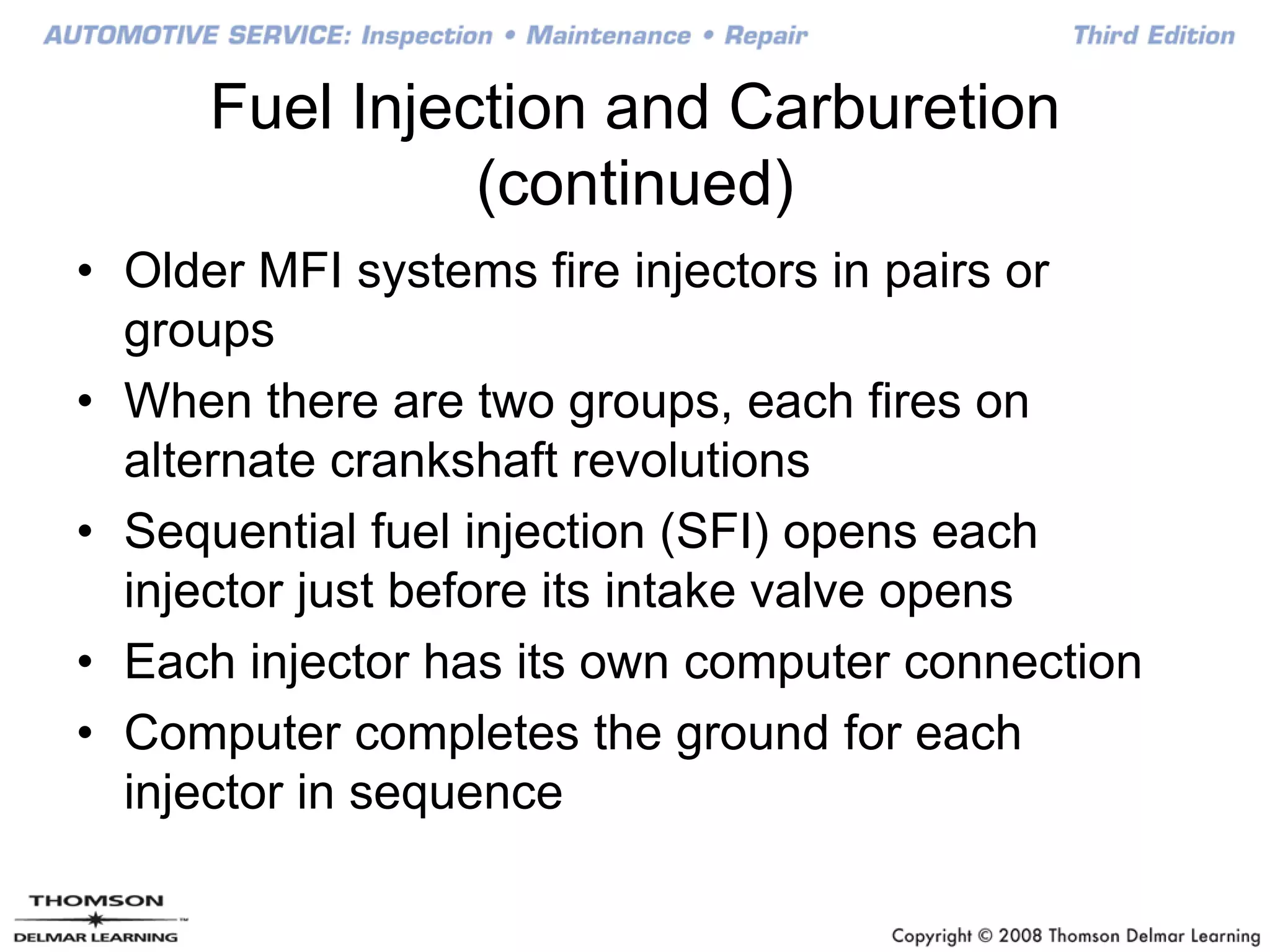
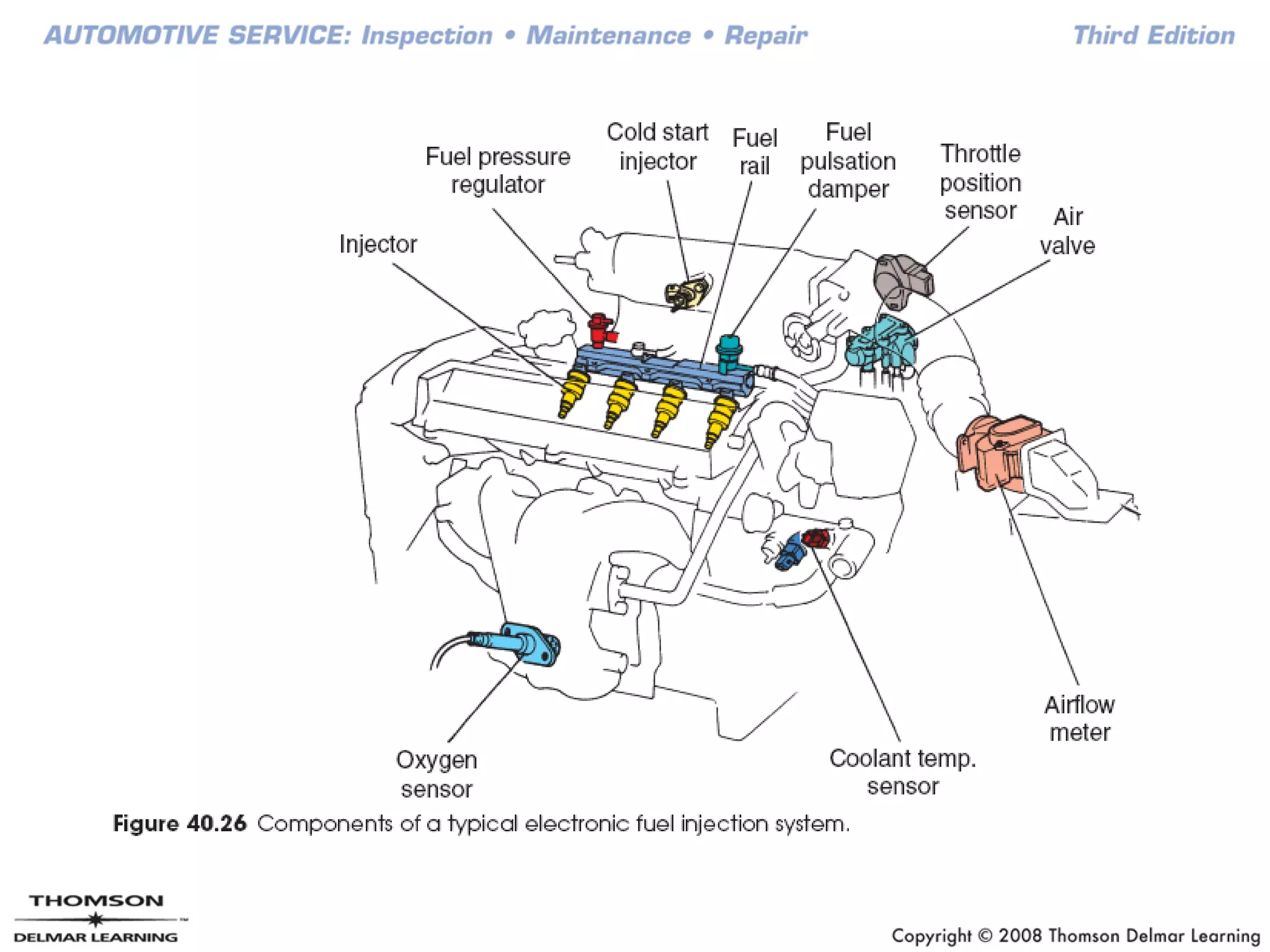
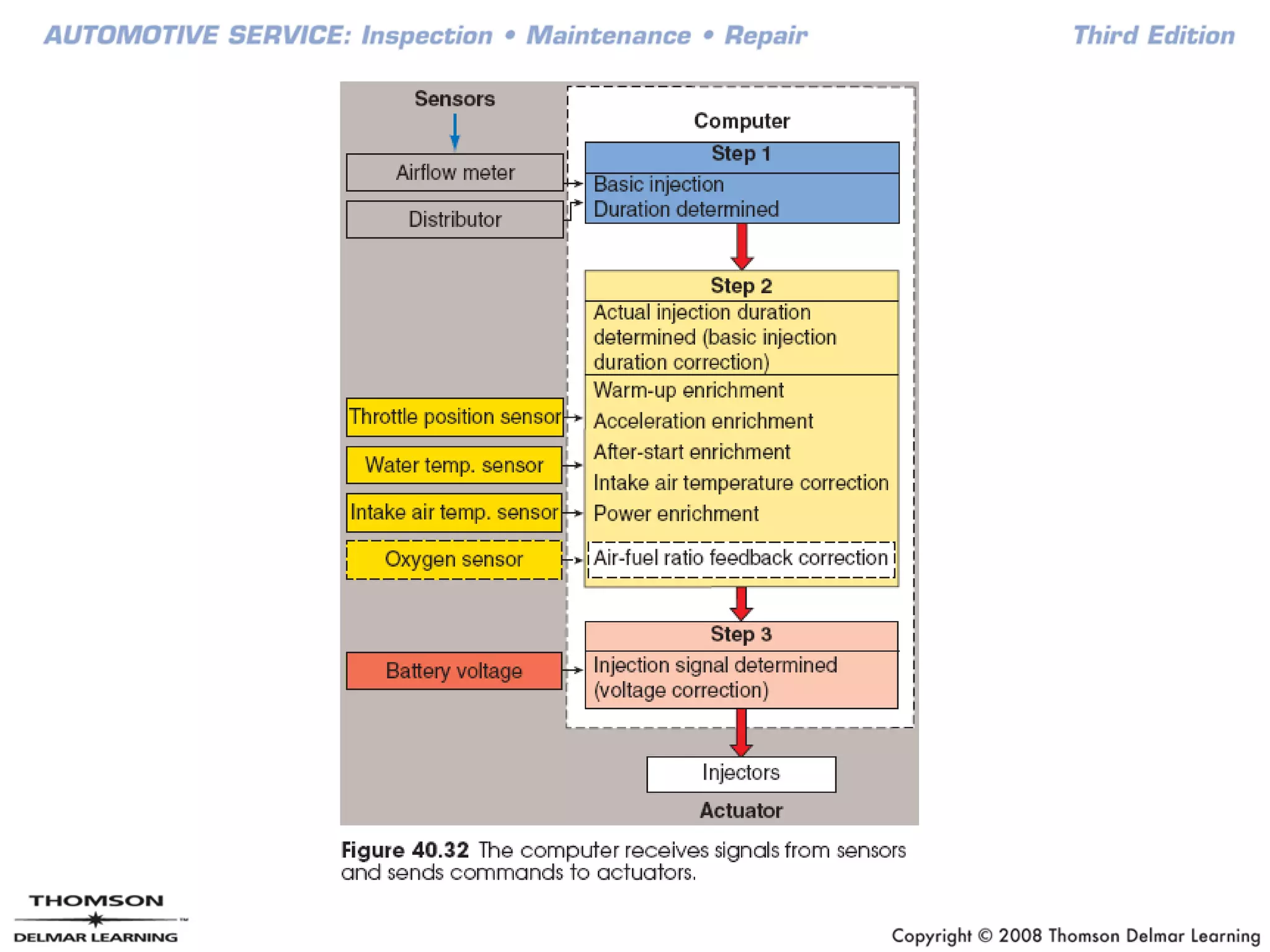
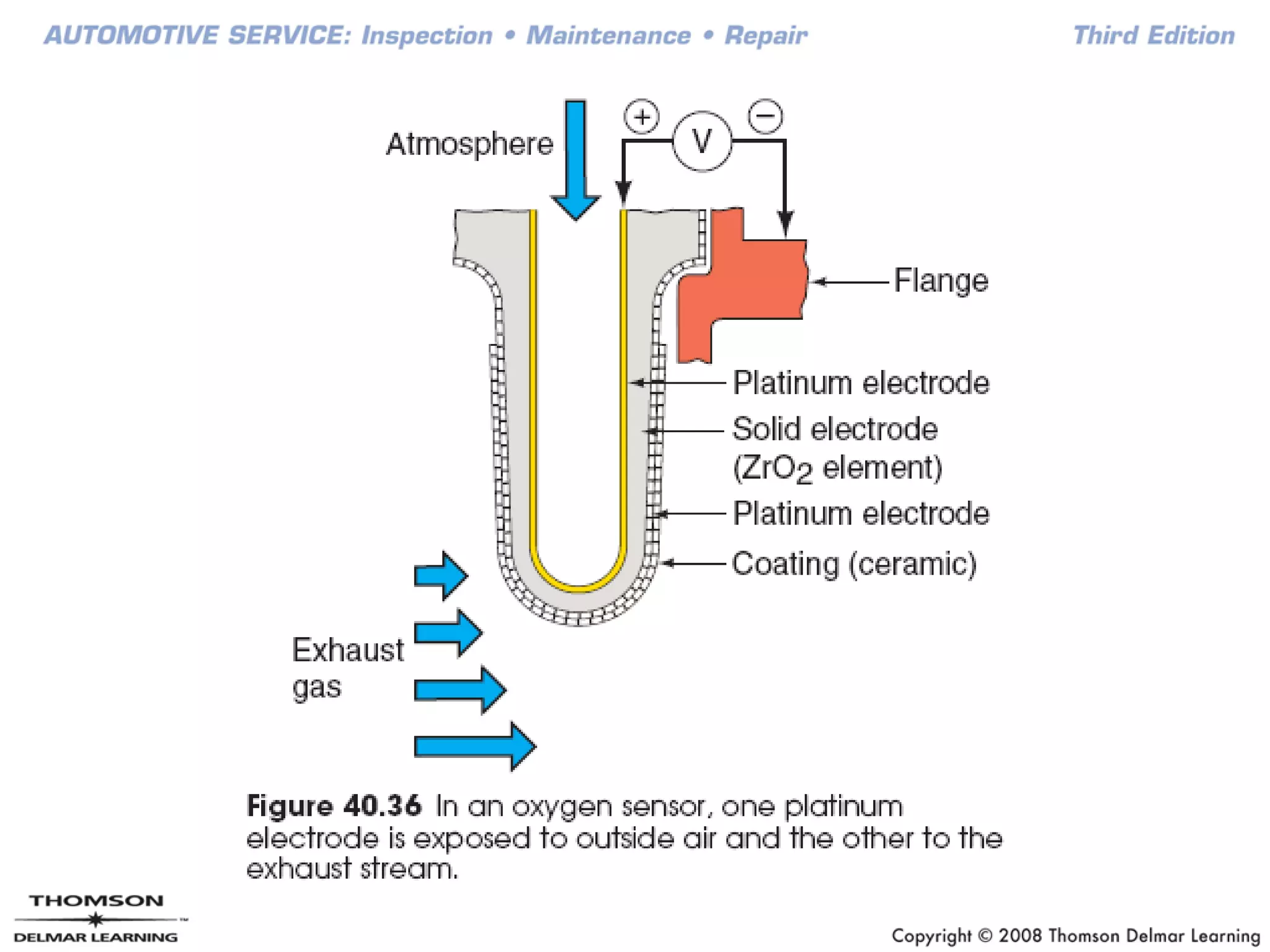
Fuel System Fundamentals
Chapter 40
Objectives
• Explain the operation of the various carburetor
systems
• Compare fuel injection to carburetion
• Identify the different types of fuel injection
• Describe the design and function of electronic
fuel injection components
• Understand how a computer feedback system
works
Introduction
• Fuel system delivers proper mixture of air and
fuel to be burned efficiently
• Must store enough fuel so the car can complete
a trip of a few hundred miles
• This chapter gives an overview of operation,
uses, and advantages of different fuel systems
Fuel System
• Fuel delivery system includes:
– Storage tank
– Pump
– Pressure regulator
– Filters
– Fuel lines
– Hoses
• Fuel induction system provides burnable air-fuel
mixture
Fuel Tanks
• Fuel tanks hold 12 – 20 gallons
– Corrosive-resistant galvanized steel or plastic
• Baffle prevents fuel sloshing in tank
• Fuel pickup tube installed through hole in bottom
of tank
• Cluster assembly includes pickup tube, fuel
gauge, fuel pump
– In-tank filter installed at end of pickup tube
• Tank has expansion and overfill protection
Fuel Lines, Hoses, and Fittings
• Steel lines made of seamless tubing run the
length of the frame
– Transport fuel from tank to engine
• Hoses used for flexible connections
Fuel Pumps
• Fuel from pump flows in a fuel rail loop between
engine and fuel tank
– Pressure regulator controls system pressure
• Electric fuel pump has one-way check valve that
maintains pressure when engine is off
– Submerged in well of fuel so cannot spark
• Electric fuel pumps on modern vehicles
computer controlled
• Pump remains on when engine is cranking or
running
Video Link
Testing a Fuel Pump
Fuel Filters
• Located in fuel line or tank
• Outlet filters installed on outlet side of fuel pump
• Fuel injection systems require large, heavy-duty
filters
– Filter out smaller particles of dirt while allowing
pump to supply fuel
Fuel Injection and Carburetion
• Atomization – fuel suspended in air in tiny drops
• Vaporization – atomized fuel turns into gas
• Modern vehicles use fuel injections
– Older vehicles use carburetors
• Carburetors atomize air and fuel
– Mounted on top of intake manifold
• Inside carburetor a venturi restricts airflow
– Fuel drawn into stream of air flowing through the
carburetor
Fuel Injection and Carburetion
(continued)
• Airflow changed by opening the throttle plate
– Butterfly valve in bottom of carburetor
• Throttle plate opens when accelerator
depressed
• Float circuit works as a toilet does
• Main jet provides opening to meter fuel amount
• Accelerator pump provides extra fuel when car is
accelerated quickly
• Choke restricts incoming air
Fuel Injection and Carburetion
(continued)
• Many types of fuel injection systems:
– Mechanical
– Electronic
– Throttle-body injection (TBI)
– Central fuel injection (CFI)
– Port injection
– Sequential fuel injection
– Multiport fuel injection (MFI)
– Central multiport fuel injection (CMFI)
• Fuel injectors fed from top or from bottom
– Bottom-feed injectors used in TBI systems
Fuel Injection and Carburetion
(continued)
• Older MFI systems fire injectors in pairs or
groups
• When there are two groups, each fires on
alternate crankshaft revolutions
• Sequential fuel injection (SFI) opens each
injector just before its intake valve opens
• Each injector has its own computer connection
• Computer completes the ground for each
injector in sequence
Pressure Regulator Operation
• Fuel pressure regulator controls systems
maximum pressure
• Port injectors exposed to intake manifold
vacuum
• Returnless systems have one fuel line between
the fuel pump and fuel rail to injectors
– Fuel does not move through fuel rail
• Excess fuel returns to tank by way of regulator in
fuel gauge sending unit
Electronic Fuel System Operation
• Fuel injectors are electromagnetic solenoid
controlled nozzles
• Each injector supplied with power when ignition
is on
– Computer controls the ground or power to
complete the circuit
• Injector plunger pulled against spring tension by
magnetic field
• Thermal time switch limits the maximum time the
injector can operate
Airflow Measurement
• Different ways of determining amount of air
flowing into the engine
• Speed density systems use MAP sensor and
engine rpm to calculate air entering engine
• Airflow sensor measures volume of air
– Vane-type mass airflow (MAF) sensor
– Heated resistor MAF sensor
– Hot wire MAF sensor
Idle Speed Control
• Idle speed raised to compensate for cold engine
or extra load
• Idle speed raised by allowing more air to bypass
throttle plate
– Auxiliary air valve
– Air by-pass valve
– Idle speed control motor
• Throttle position sensor senses how many
degrees the throttle plate is open
• Amount of fuel injected varies with temperature
Fuel Pump Relay
• Fuel pump energized during engine cranking
• If key on and engine has not been cranked for 2
seconds, fuel pump relay shuts off power
– Prevents flooding or lockup
– Prevents fuel pump from running with ignition on
in case of accident or broken fuel line
• Oil pressure switch allows fuel pump to operate
if fuel pump relay defective
Computer-Controlled Fuel Systems
• Computers meter fuel precisely
• Powertrain control module (PCM) controls
engine performance
– Includes fuel system
• Automotive ignition and electronics are complex
specialty areas
• This chapter provides a general idea of the
operation of the system
Feedback Fuel Systems
• Computer system includes
– Computer
– Sensors
– Actuators
• Computer feedback cars have oxygen sensor in
exhaust manifold
• In feedback fuel system, computer makes
corrective changes to air-fuel mixture
• Feedback carburetors used on older cars
Feedback Fuel Systems (continued)
• Open loop – oxygen sensor does not send
signals to the computer
– Oxygen sensor operates at 600°F
• Zirconium oxide works like a small battery
– Oxygen ions transfer negative charge to exhaust
side of sensor
– Rich mixture generates 0.45 volt or higher
• Lambda – the ratio of the engines air-fuel
mixture to ideal mixture
• Some oxygen sensors are heated so computer
goes into closed loop sooner
Feedback Fuel Systems (continued)
• Wide range O2 sensor is two nested zirconia
sensors
– Energy difference between the two determines
air-fuel ratio
• PCM maintains O2 sensor output at constant
voltage by applying positive, negative current
• Outside sensor measures exhaust oxygen
• Inside sensor samples outside air
Feedback Fuel Systems (continued)
• Common rail connects injectors with diesel fuel
under high pressure
– Atomizes fuel, mixing it with air
• GDI – gasoline injected directly into combustion
chamber
– Runs the engine with a lean mixture
– Increases fuel economy by as much as 30%
– Reduces exhaust emissions
– Require EGR valve to control NOX emissions

Fuel system fundamentals

  • 1.
  • 2.
    Objectives • Explain theoperation of the various carburetor systems • Compare fuel injection to carburetion • Identify the different types of fuel injection • Describe the design and function of electronic fuel injection components • Understand how a computer feedback system works
  • 3.
    Introduction • Fuel systemdelivers proper mixture of air and fuel to be burned efficiently • Must store enough fuel so the car can complete a trip of a few hundred miles • This chapter gives an overview of operation, uses, and advantages of different fuel systems
  • 4.
    Fuel System • Fueldelivery system includes: – Storage tank – Pump – Pressure regulator – Filters – Fuel lines – Hoses • Fuel induction system provides burnable air-fuel mixture
  • 5.
    Fuel Tanks • Fueltanks hold 12 – 20 gallons – Corrosive-resistant galvanized steel or plastic • Baffle prevents fuel sloshing in tank • Fuel pickup tube installed through hole in bottom of tank • Cluster assembly includes pickup tube, fuel gauge, fuel pump – In-tank filter installed at end of pickup tube • Tank has expansion and overfill protection
  • 7.
    Fuel Lines, Hoses,and Fittings • Steel lines made of seamless tubing run the length of the frame – Transport fuel from tank to engine • Hoses used for flexible connections
  • 8.
    Fuel Pumps • Fuelfrom pump flows in a fuel rail loop between engine and fuel tank – Pressure regulator controls system pressure • Electric fuel pump has one-way check valve that maintains pressure when engine is off – Submerged in well of fuel so cannot spark • Electric fuel pumps on modern vehicles computer controlled • Pump remains on when engine is cranking or running
  • 9.
  • 10.
    Fuel Filters • Locatedin fuel line or tank • Outlet filters installed on outlet side of fuel pump • Fuel injection systems require large, heavy-duty filters – Filter out smaller particles of dirt while allowing pump to supply fuel
  • 11.
    Fuel Injection andCarburetion • Atomization – fuel suspended in air in tiny drops • Vaporization – atomized fuel turns into gas • Modern vehicles use fuel injections – Older vehicles use carburetors • Carburetors atomize air and fuel – Mounted on top of intake manifold • Inside carburetor a venturi restricts airflow – Fuel drawn into stream of air flowing through the carburetor
  • 13.
    Fuel Injection andCarburetion (continued) • Airflow changed by opening the throttle plate – Butterfly valve in bottom of carburetor • Throttle plate opens when accelerator depressed • Float circuit works as a toilet does • Main jet provides opening to meter fuel amount • Accelerator pump provides extra fuel when car is accelerated quickly • Choke restricts incoming air
  • 15.
    Fuel Injection andCarburetion (continued) • Many types of fuel injection systems: – Mechanical – Electronic – Throttle-body injection (TBI) – Central fuel injection (CFI) – Port injection – Sequential fuel injection – Multiport fuel injection (MFI) – Central multiport fuel injection (CMFI) • Fuel injectors fed from top or from bottom – Bottom-feed injectors used in TBI systems
  • 16.
    Fuel Injection andCarburetion (continued) • Older MFI systems fire injectors in pairs or groups • When there are two groups, each fires on alternate crankshaft revolutions • Sequential fuel injection (SFI) opens each injector just before its intake valve opens • Each injector has its own computer connection • Computer completes the ground for each injector in sequence
  • 17.
    Pressure Regulator Operation •Fuel pressure regulator controls systems maximum pressure • Port injectors exposed to intake manifold vacuum • Returnless systems have one fuel line between the fuel pump and fuel rail to injectors – Fuel does not move through fuel rail • Excess fuel returns to tank by way of regulator in fuel gauge sending unit
  • 18.
    Electronic Fuel SystemOperation • Fuel injectors are electromagnetic solenoid controlled nozzles • Each injector supplied with power when ignition is on – Computer controls the ground or power to complete the circuit • Injector plunger pulled against spring tension by magnetic field • Thermal time switch limits the maximum time the injector can operate
  • 20.
    Airflow Measurement • Differentways of determining amount of air flowing into the engine • Speed density systems use MAP sensor and engine rpm to calculate air entering engine • Airflow sensor measures volume of air – Vane-type mass airflow (MAF) sensor – Heated resistor MAF sensor – Hot wire MAF sensor
  • 21.
    Idle Speed Control •Idle speed raised to compensate for cold engine or extra load • Idle speed raised by allowing more air to bypass throttle plate – Auxiliary air valve – Air by-pass valve – Idle speed control motor • Throttle position sensor senses how many degrees the throttle plate is open • Amount of fuel injected varies with temperature
  • 22.
    Fuel Pump Relay •Fuel pump energized during engine cranking • If key on and engine has not been cranked for 2 seconds, fuel pump relay shuts off power – Prevents flooding or lockup – Prevents fuel pump from running with ignition on in case of accident or broken fuel line • Oil pressure switch allows fuel pump to operate if fuel pump relay defective
  • 23.
    Computer-Controlled Fuel Systems •Computers meter fuel precisely • Powertrain control module (PCM) controls engine performance – Includes fuel system • Automotive ignition and electronics are complex specialty areas • This chapter provides a general idea of the operation of the system
  • 24.
    Feedback Fuel Systems •Computer system includes – Computer – Sensors – Actuators • Computer feedback cars have oxygen sensor in exhaust manifold • In feedback fuel system, computer makes corrective changes to air-fuel mixture • Feedback carburetors used on older cars
  • 26.
    Feedback Fuel Systems(continued) • Open loop – oxygen sensor does not send signals to the computer – Oxygen sensor operates at 600°F • Zirconium oxide works like a small battery – Oxygen ions transfer negative charge to exhaust side of sensor – Rich mixture generates 0.45 volt or higher • Lambda – the ratio of the engines air-fuel mixture to ideal mixture • Some oxygen sensors are heated so computer goes into closed loop sooner
  • 28.
    Feedback Fuel Systems(continued) • Wide range O2 sensor is two nested zirconia sensors – Energy difference between the two determines air-fuel ratio • PCM maintains O2 sensor output at constant voltage by applying positive, negative current • Outside sensor measures exhaust oxygen • Inside sensor samples outside air
  • 29.
    Feedback Fuel Systems(continued) • Common rail connects injectors with diesel fuel under high pressure – Atomizes fuel, mixing it with air • GDI – gasoline injected directly into combustion chamber – Runs the engine with a lean mixture – Increases fuel economy by as much as 30% – Reduces exhaust emissions – Require EGR valve to control NOX emissions